Configuration
54
7SS52 V4 Manual
C53000-G1176-C182-3
Enter a busbar name of not more than 8 characters into the box
Name long
. This
name will be displayed as movable text within the chart. The long name will also
show in the measured value boxes of the busbar.
Select one of the 12 busbar sections (BB01 to BB12) or bus coupler sections (TB01
to TB12) from the box
Busbar section
.
Click
Select
to choose the on-line colour of the busbar. The Plant Visualization will
show the attachment of the feeders and measuring systems to the corresponding
busbar in the colour you specify here.
Click
OK
to apply the settings and to close the dialog box.
Bus coupler zones are bus zones which are used exclusively for connecting bus zones
and which have no feeder bays. In most cases they occur in connection with bus cou-
plers. An example is given in Figure 4-16, page 66 (BS1, BS2).
4.3.4
Defining Bays
Isolators, transformers and circuit breakers must be assigned to a certain bay. A bay
in the substation chart is represented by a bay name. First you insert a wildcard for the
bay name. Next you specify a short name and a long name for the bay name.
To insert a wildcard for the bay name you must:
Click
Tools
→
Insert Bay Name
on the menu bar. Alternatively, you can click the
button on the toolbar.
Click the position on the substation chart where you wish to insert the bay name. A
wildcard in the form of an asterisk is inserted. Click on the desired positions to insert
further wildcards for bay names.
To specify the short text and long text for a bay name you must:
Right-click the wildcard in question. Click
Object properties
in the context menu.
Or you can double-click the wildcard. Both methods will open the dialog box
Object
properties - Bay Name
.
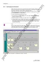
Figure 4-9 Dialog box
Object Properties - Bay Name
Note
After you have released the mouse button, the program verifies whether the wildcard
superposes other elements. If this is the case, you will receive a corresponding mes-
sage and the wildcard will not be inserted into the substation chart.
www
. ElectricalPartManuals
. com
Содержание SIPROTEC 7SS522 V4.6
Страница 326: ...Maintenance and Repair 310 7SS52 V4 Manual C53000 G1176 C182 3 w w w E l e c t r i c a l P a r t M a n u a l s c o m ...
Страница 432: ...Appendix 416 7SS52 V4 Manual C53000 G1176 C182 3 w w w E l e c t r i c a l P a r t M a n u a l s c o m ...
Страница 438: ...Index 422 7SS52 V4 Manual C53000 G1176 C182 34 w w w E l e c t r i c a l P a r t M a n u a l s c o m ...


