Stored Indications in the SIPROTEC 5 Device
In your SIPROTEC 5 device you can also configure indications as stored. This type of configuration can be used
for LEDs as well as for output contacts. The configured output (LED or contact) is activated until it is acknowl-
edged. Confirmation occurs via:
•
On-site operation panel
•
DIGSI 5
•
Binary Input
•
Log of substation automation technology
Configuration of Stored Indications with DIGSI 5
•
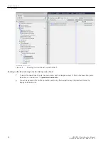
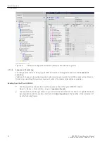
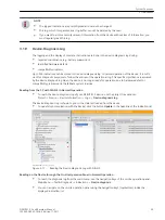
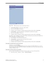
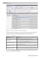
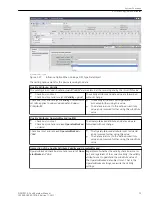
In the Information Routing of each device set up in DIGSI 5, you can route binary signals, among others,
to LEDs and output contacts. For this, go to the project tree.
Project → Device → Information Routing
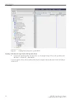
•
Click the routing field of your binary indication in the desired LED or binary output column in the routing
range of the targets by clicking the right mouse button.
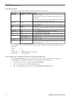
You are offered the following options:
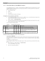
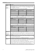
Table 3-4
Overview of Routing Options
Routing Options
LEDs BOs
BIs
Description
H
(active)
X
The signal is routed as active with voltage.
L
(active)
X
The signal is routed as active without voltage.
U
(unlatched)
X
X
The signal is routed as unsaved. Activation and reset of
the output (LED, BO) occurs automatically via the
binary-signal value.
L
(latched)
X
X
The binary signal is latched when the output (LED) is
activated. To reset, a targeted confirmation must occur.
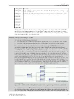
Confirmation of Stored Indications on the On-Site Operation Panel
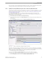
Confirmation via LED Reset
Operating the button first brings about the activation of all LEDs (LED test) when pressed and when released
the resetting of all stored indications. Stored LEDs, output contacts and spontaneous fault messages (display)
are reset.
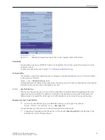
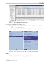
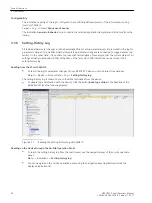
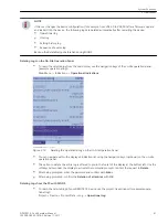
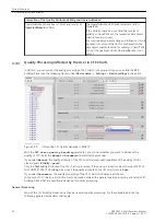
Confirmation via the operating menu
Use the navigation buttons of the on-site operation panel, in order to reach the reset functions from the main
menu.
•
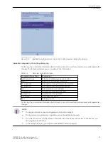
Select: Main menu → Device functions → Reset functions
You are offered different reset options.
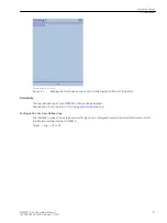
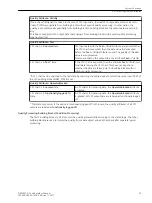
•
Open the corresponding submenu.
3.1.11
System Functions
3.1 Indications
62
SIPROTEC 5, Fault Recorder, Manual
C53000-G5040-C018-5, Edition 11.2017
Содержание SIPROTEC 5
Страница 8: ...8 SIPROTEC 5 Fault Recorder Manual C53000 G5040 C018 5 Edition 11 2017 ...
Страница 18: ...18 SIPROTEC 5 Fault Recorder Manual C53000 G5040 C018 5 Edition 11 2017 ...
Страница 134: ...134 SIPROTEC 5 Fault Recorder Manual C53000 G5040 C018 5 Edition 11 2017 ...
Страница 212: ...212 SIPROTEC 5 Fault Recorder Manual C53000 G5040 C018 5 Edition 11 2017 ...
Страница 422: ...422 SIPROTEC 5 Fault Recorder Manual C53000 G5040 C018 5 Edition 11 2017 ...
Страница 426: ...426 SIPROTEC 5 Fault Recorder Manual C53000 G5040 C018 5 Edition 11 2017 ...
Страница 452: ...452 SIPROTEC 5 Fault Recorder Manual C53000 G5040 C018 5 Edition 11 2017 ...
Страница 490: ...490 SIPROTEC 5 Fault Recorder Manual C53000 G5040 C018 5 Edition 11 2017 ...

