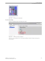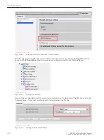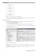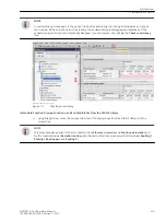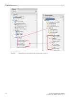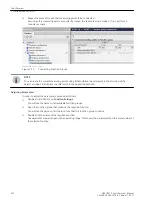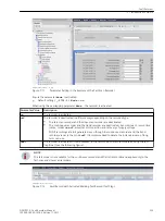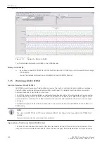
[dwflussr-161012-01.tif, 1, en_US]
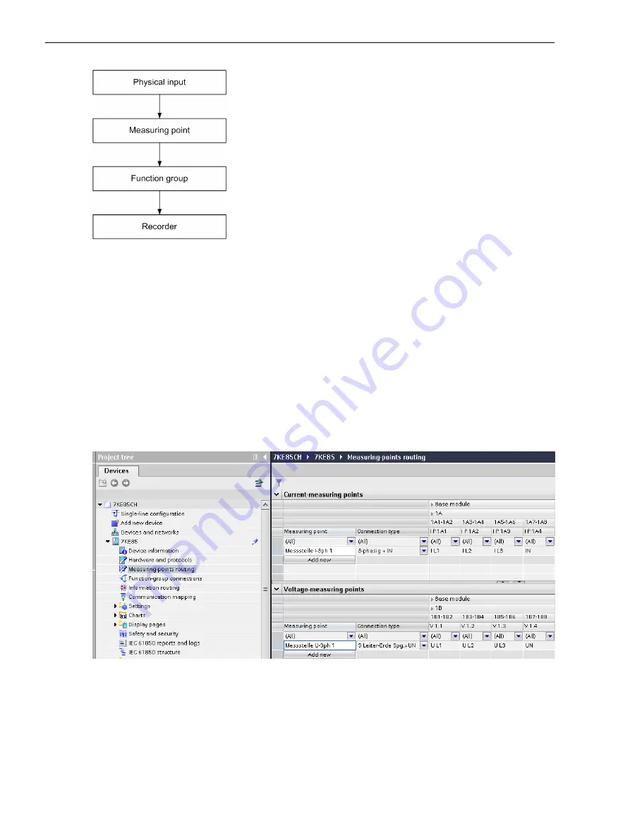
Figure 7-5
Signal Flow Direction in the Fault Recorder
In the following are the most important steps for setting the parameters for your fault recorder. A detailed
description of DIGSI 5 options can be found in the DIGSI Help.
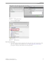
Routing Measuring Points
You can use the Measuring-point routing matrix to route the physical inputs of a inputs of the SIPROTEC 5
device to the inputs of current and voltage measuring points.
²
Double-click Measuring point routing.
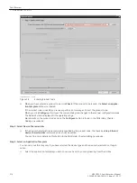
²
Finally, click Add. A window for selecting the phase characteristic (3-phase or 1-phase) appears.
²
Select both for the current and the voltage measuring points either the 3-phase or 1-phase characteristic.
²
Select the connection type.
²
Route the phases on the measuring points.
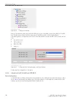
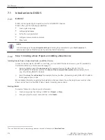
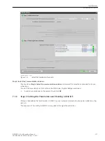
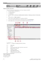
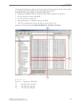
[scmes7ke-180213-01.tif, 1, en_US]
Figure 7-6
Route Measuring Points
Detailed information on the clamp designations, for example 1A, is in the Hardware Manual and in the hard-
ware configuration.
In addition you can use the Current measuring points and Voltage measuring points window to add other
measuring points to the application.
Fault Recorder
7.1 Introduction to DIGSI 5
218
SIPROTEC 5, Fault Recorder, Manual
C53000-G5040-C018-5, Edition 11.2017
Содержание SIPROTEC 5
Страница 8: ...8 SIPROTEC 5 Fault Recorder Manual C53000 G5040 C018 5 Edition 11 2017 ...
Страница 18: ...18 SIPROTEC 5 Fault Recorder Manual C53000 G5040 C018 5 Edition 11 2017 ...
Страница 134: ...134 SIPROTEC 5 Fault Recorder Manual C53000 G5040 C018 5 Edition 11 2017 ...
Страница 212: ...212 SIPROTEC 5 Fault Recorder Manual C53000 G5040 C018 5 Edition 11 2017 ...
Страница 422: ...422 SIPROTEC 5 Fault Recorder Manual C53000 G5040 C018 5 Edition 11 2017 ...
Страница 426: ...426 SIPROTEC 5 Fault Recorder Manual C53000 G5040 C018 5 Edition 11 2017 ...
Страница 452: ...452 SIPROTEC 5 Fault Recorder Manual C53000 G5040 C018 5 Edition 11 2017 ...
Страница 490: ...490 SIPROTEC 5 Fault Recorder Manual C53000 G5040 C018 5 Edition 11 2017 ...

