


Checking the Voltage Connections and Polarity Check
Voltage and Phase Sequence Check
If the device is connected to voltage transformers, these connections are checked using primary values. For
devices without voltage transformer connection this section can be bypassed.
The voltage transformer connections are tested for that measuring location or side to which they are assigned
(address 261, refer to Section
under margin heading “Assignment of Voltage
Measuring Inputs”).
•
Having energised the voltage transformer set, none of the measurement monitoring functions in the
device may respond.
–
If there is a fault annunciation, however, the event log or spontaneous annunciation could be
checked to investigate the reason for it.
–
At the indication of voltage summation error check also the assignment of the single-phase voltage
input and the matching factors. For further details see Section
under
margin heading “Assignment of Voltage Measuring Inputs”.
–
At the indication of symmetry monitoring there might actually be asymmetries of the primary
system. If they are part of normal operation, the corresponding monitoring function is set less sensi-
tive (see Section
under margin heading “Voltage Balance”).
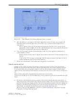
The voltages can be read on the display at the front, or called up in the PC via the operator or service interface,
and compared with the actual measured quantities as primary or secondary values. Besides the magnitudes of
the phase-to-phase and the phase-to-earth voltages, the phase angles can be read out, thus enabling to verify
the correct phase sequence and polarity of individual voltage transformers. The voltages can also be read out
with the “Web Monitor” (see
[OptUnresolvedLink]funktionsweise[/OptUnresolvedLink]
).
•
The voltage magnitudes should be almost equal. All angles must be approximately 120° to each other in
a 3-phase system.
–
If the measured quantities are not plausible, the connections must be checked and revised after
switching off the measuring location. If the phase difference angle between two voltages is 60°
instead of 120°, one voltage must be polarity-reversed. The same applies if there are phase-to-phase
voltages which almost equal the phase-to-earth voltages instead of having a value that is √3 greater.
The measurements are to be repeated after setting the connections right.
–
In general, the phase rotation is a clockwise phase rotation. If the system has an counter-clockwise
phase rotation, this must have been considered when the power system data was set (address 271
PHASE SEQ.
Sequence”). Wrong phase rotation is indicated with the annunciation
Fail Ph. Seq. U
(No 176).
The measured value allocation must be checked and corrected, if required, after the measuring loca-
tion has been isolated. The phase rotation check must then be repeated.
3.3.12
Mounting and Commissioning
3.3 Commissioning
386
SIPROTEC 4, 7UT6x, Manual
C53000-G1176-C230-5, Edition 09.2016
Содержание SIPROTEC 4 7UT6 Series
Страница 394: ...394 SIPROTEC 4 7UT6x Manual C53000 G1176 C230 5 Edition 09 2016 ...
Страница 482: ...482 SIPROTEC 4 7UT6x Manual C53000 G1176 C230 5 Edition 09 2016 ...
Страница 504: ...504 SIPROTEC 4 7UT6x Manual C53000 G1176 C230 5 Edition 09 2016 ...
Страница 522: ...522 SIPROTEC 4 7UT6x Manual C53000 G1176 C230 5 Edition 09 2016 ...
Страница 528: ...528 SIPROTEC 4 7UT6x Manual C53000 G1176 C230 5 Edition 09 2016 ...
Страница 538: ...538 SIPROTEC 4 7UT6x Manual C53000 G1176 C230 5 Edition 09 2016 ...
Страница 664: ...664 SIPROTEC 4 7UT6x Manual C53000 G1176 C230 5 Edition 09 2016 ...
Страница 666: ...666 SIPROTEC 4 7UT6x Manual C53000 G1176 C230 5 Edition 09 2016 ...
Страница 683: ...Z Zero sequence currents 109 Index SIPROTEC 4 7UT6x Manual 683 C53000 G1176 C230 5 Edition 09 2016 ...
Страница 684: ...684 SIPROTEC 4 7UT6x Manual C53000 G1176 C230 5 Edition 09 2016 ...


