

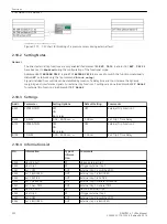


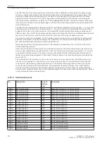


Settings
Addr.
Parameter
Setting Options
Default Setting
Comments
8201
TRIP Cir. SUP.
ON
OFF
OFF
TRIP Circuit Supervision
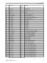
Information List
No.
Information
Type of
Informa-
tion
Comments
6851
>BLOCK TripC
SP
>BLOCK Trip circuit supervision
6852
>TripC trip rel
SP
>Trip circuit supervision: trip relay
6853
>TripC brk rel.
SP
>Trip circuit supervision: breaker relay
6861
TripC OFF
OUT
Trip circuit supervision OFF
6862
TripC BLOCKED
OUT
Trip circuit supervision is BLOCKED
6863
TripC ACTIVE
OUT
Trip circuit supervision is ACTIVE
6864
TripC ProgFail
OUT
Trip Circuit blk. Bin. input is not set
6865
FAIL: Trip cir.
OUT
Failure Trip Circuit
Monitoring
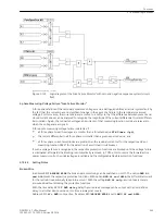
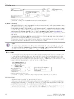
Broken Wire Detection, Fuse Failure Monitoring
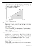
Broken Wire
During steady-state operation the broken wire monitoring registers interruptions in the secondary circuit of
the current transformers. In addition to the hazard potential caused by high voltages in the secondary circuit,
this kind of interruption simulates differential currents to the differential protection, such as those evoked by
faults in the protected object.
The broken-wire monitor scans the transient behaviour of the currents of each phase for each measuring loca-
tion. The instantaneous current values are checked for plausibility. If an instantaneous value does not corre-
spond to the expected value although the other steady-state currents continue to flow, a broken wire is
considered. Moreover it is checked, whether the current decays strongly or drops abruptly to 0 (from > 0.1 ·
Ι
N
), or no zero crossing is registered. At the same time, the currents flowing in other phases must not exceed 2
·
Ι
N
.
The protection functions which react on unsymmetrical currents are blocked as well provided they are
assigned to the defective measuring location: the time overcurrent protection for residual current and the
unbalanced load protection. The device issues the message “Broken wire” indicating also the affected phase
and measuring location.
The blocking is released as soon as a current flow is registered again in the appropriate phase of the device
concerned.
The following figure shows the logic of the wire break detection for 3 measuring locations.
2.19.2.3
2.19.2.4
2.19.3
2.19.3.1
Functions
2.19 Monitoring Functions
262
SIPROTEC 4, 7UT6x, Manual
C53000-G1176-C230-5, Edition 09.2016
Содержание SIPROTEC 4 7UT6 Series
Страница 394: ...394 SIPROTEC 4 7UT6x Manual C53000 G1176 C230 5 Edition 09 2016 ...
Страница 482: ...482 SIPROTEC 4 7UT6x Manual C53000 G1176 C230 5 Edition 09 2016 ...
Страница 504: ...504 SIPROTEC 4 7UT6x Manual C53000 G1176 C230 5 Edition 09 2016 ...
Страница 522: ...522 SIPROTEC 4 7UT6x Manual C53000 G1176 C230 5 Edition 09 2016 ...
Страница 528: ...528 SIPROTEC 4 7UT6x Manual C53000 G1176 C230 5 Edition 09 2016 ...
Страница 538: ...538 SIPROTEC 4 7UT6x Manual C53000 G1176 C230 5 Edition 09 2016 ...
Страница 664: ...664 SIPROTEC 4 7UT6x Manual C53000 G1176 C230 5 Edition 09 2016 ...
Страница 666: ...666 SIPROTEC 4 7UT6x Manual C53000 G1176 C230 5 Edition 09 2016 ...
Страница 683: ...Z Zero sequence currents 109 Index SIPROTEC 4 7UT6x Manual 683 C53000 G1176 C230 5 Edition 09 2016 ...
Страница 684: ...684 SIPROTEC 4 7UT6x Manual C53000 G1176 C230 5 Edition 09 2016 ...