background image

8.1.2

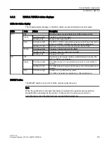
NX10.3 / NX15.3 status displays

LEDs for status display

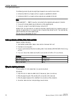
The following status displays on the NX modules provide information about its state:

LEDs

Color

Status

Description

RDY

Off

Electronic power supply outside permissible tolerance range

Green

Continuous light

The NX10.3 / NX15.3 is ready.

Flashing 2 Hz

Writing to SD card of the PPU.

Red

Continuous light

The NX10.3 / NX15.3 is presently powering up and at least one fault is 

active (e.g. RESET, watchdog monitoring, basic system fault). 

Flashing 0.5 Hz

Boot error (e.g. firmware cannot be loaded into the RAM)

Yellow

Continuous light

Firmware is being loaded into the RAM.

Flashing 0.5 Hz

Firmware cannot be loaded into the RAM.

Flashing 2 Hz

Firmware CRC fault

DP

Off

Electronics power supply outside permissible tolerance range: The 

NX10.3 / NX15.3 is not ready.

Green

Continuous light

CU_LINK is ready for communication and cyclic communication is 

running.

Flashing 0.5 Hz

CU_LINK is ready for communication and cyclic communication is not 

running.

Red

Continuous light

At least one CU_LINK fault is present.
CU_LINK is not ready for operation (e.g. after switching on).

RESET button

The RESET button is on the front of the module under the cover.

Note
When the pushbutton is actuated, the locally connected drive systems are brought to a 

standstill with no feedback to the control. In other words, the drive and control run 

asynchronously once the drive has been successfully powered up.

Connectable components

8.1 NX10.3 / NX15.3

PPU 1740

Equipment Manual, 01/2019, A5E47615272B AA 

85

Содержание SINUMERIK ONE PPU 1740 Series

Страница 1: ... ONE PPU 1740 1900 01 2019 A5E47615272B AA Preface Fundamental safety instructions 1 System overview 2 System characteristics 3 Application planning 4 Installing 5 Service and maintenance 6 Interface description 7 Connectable components 8 Technical data 9 Spare parts and accessories 10 Appendix 11 ...

Страница 2: ...onnel are those who based on their training and experience are capable of identifying risks and avoiding potential hazards when working with these products systems Proper use of Siemens products Note the following WARNING Siemens products may only be used for the applications described in the catalog and in the relevant technical documentation If products and components from other manufacturers ar...

Страница 3: ... mail to the following address mailto docu motioncontrol siemens com mySupport Documentation At the following address https support industry siemens com My ww en documentation you can find information on how to create your own individual documentation based on Siemens content and adapt it for your own machine documentation Training At the following address http www siemens com sitrain you can find...

Страница 4: ... maintenance Note regarding the General Data Protection Regulation Siemens observes standard data protection principles in particular the principle of privacy by design That means that this product does not process store any personal data only technical functional data e g time stamps If a user links this data with other data e g a shift schedule or stores personal data on the same storage medium ...

Страница 5: ... 2 LED display 28 3 2 3 7 segment display 31 3 2 4 DIAG RESET button 32 3 2 5 Start up and mode selector switch 33 3 2 6 Operation when wearing gloves 34 3 2 7 Operating with gestures 35 3 3 Memory card interface 37 3 3 1 SD card system 37 3 3 2 Inserting the system SD card 38 3 4 System overview 40 4 Application planning 43 4 1 Grounding concept 43 4 2 EMC compatibility 44 4 3 Climatic and mechan...

Страница 6: ...cal data 75 7 5 DRIVE CLiQ 77 7 5 1 DRIVE CLiQ interface 77 7 6 Handwheel 78 7 7 USB 81 8 Connectable components 83 8 1 NX10 3 NX15 3 83 8 1 1 Description 83 8 1 2 NX10 3 NX15 3 status displays 85 8 1 3 Mounting 86 8 1 4 Dimension drawing 87 8 1 5 Connecting 88 8 1 6 Technical Data 91 9 Technical data 93 9 1 Relevant directives and standards 95 10 Spare parts and accessories 99 11 Appendix 101 11 ...

Страница 7: ...of the power connections and the protective conductor connection 5 Check whether the existing auxiliary supply circuits are de energized 6 Ensure that the motors cannot move 7 Identify all other dangerous energy sources e g compressed air hydraulic systems or water Switch the energy sources to a safe state 8 Check that the correct drive system is completely locked After you have completed the work...

Страница 8: ...ck if there is no ground connection For missing or incorrectly implemented protective conductor connection for devices with protection class I high voltages can be present at open exposed parts which when touched can result in death or severe injury Ground the device in compliance with the applicable regulations WARNING Spread of fire from built in devices In the event of fire outbreak the enclosu...

Страница 9: ...imum clearance as ventilation clearance for the respective component NOTICE Overheating due to inadmissible mounting position The device may overheat and therefore be damaged if mounted in an inadmissible position Only operate the device in admissible mounting positions WARNING Unexpected movement of machines caused by inactive safety functions Inactive or non adapted safety functions can trigger ...

Страница 10: ...rated functions If you want to use Safety Integrated functions you must observe the safety notices in the Safety Integrated manuals Fundamental safety instructions 1 1 General safety instructions PPU 1740 10 Equipment Manual 01 2019 A5E47615272B AA ...

Страница 11: ... transport and send electronic components modules or devices in their original packaging or in other suitable materials e g conductive foam rubber of aluminum foil Only touch components modules and devices when you are grounded by one of the following methods Wearing an ESD wrist strap Wearing ESD shoes or ESD grounding straps in ESD areas with conductive flooring Only place electronic components ...

Страница 12: ...utions but are only intended to provide support for typical tasks As the user you yourself are responsible for ensuring that the products described are operated correctly Application examples do not relieve you of your responsibility for safe handling when using installing operating and maintaining the equipment Fundamental safety instructions 1 3 Warranty and liability for application examples PP...

Страница 13: ...ls and or network segmentation are in place For additional information on industrial security measures that can be implemented please visit Industrial security https www siemens com industrialsecurity Siemens products and solutions undergo continuous development to make them more secure Siemens strongly recommends that product updates are applied as soon as they become available and that only the ...

Страница 14: ...curity concept for the installation or machine Make sure that you include all installed products into the holistic industrial security concept Protect files stored on exchangeable storage media from malicious software by with suitable protection measures e g virus scanners On completion of commissioning check all security related settings Protect the drive against unauthorized changes by activatin...

Страница 15: ...articles gases etc can occur inside and outside the components under fault conditions caused by for example Component failure Software errors Operation and or environmental conditions outside the specification External influences damage 3 Hazardous shock voltages caused by for example Component failure Influence during electrostatic charging Induction of voltages in moving motors Operation and or ...

Страница 16: ...Fundamental safety instructions 1 5 Residual risks of power drive systems PPU 1740 16 Equipment Manual 01 2019 A5E47615272B AA ...

Страница 17: ...INUMERIK ONE is characterized with A high degree of flexibility Excellent dynamic response and precision Optimum integration into networks Benefits Outstanding performance and flexibility for multi axis systems of average to high complexity thanks to scalable hardware and software Universal openness of the user interface the PLC and the NC kernel to allow integration of your specialist know how In...

Страница 18: ...ning nibbling punching in tool and mold making for high speed cutting applications for wood and glass processing for handling operations in transfer lines and rotary indexing machines for mass production and Job Shop production System overview 2 1 Application PPU 1740 18 Equipment Manual 01 2019 A5E47615272B AA ...

Страница 19: ...rect drive motors in synchronous and asynchronous design Servomotors 1FT 1FK Main spindle motors 1PH 1FE 2SP1 Direct drive motors 1FN3 1FW6 Handwheels A maximum of three handwheels can be connected Two handwheels via X143 1 using MCP and connection box Increasing the number of axes NX10 3 NX15 3 You can increase the number of axes connected to the NC using NX modules Each NX10 3 component can cont...

Страница 20: ... 6 1 0 6 30 8 ವ ವ ವ Figure 2 1 Topology example 1 6HUYRPRWRUV 6HUYRPRWRUV 3RZHU VXSSO 6 1 0 6 6 0RWRU 0RGXOH IRUPDW RRNVL H RPSDFW 3 VSLQGOH PRWRU QGXVWULDO WKHUQHW 5 9 L4 33 31 33b b b31 6 1 0 6 6 RPEL 352 1 7 6 0 7 7 SUR 338 0 3 31 Figure 2 2 Topology example 2 System overview 2 2 System configuration PPU 1740 20 Equipment Manual 01 2019 A5E47615272B AA ...

Страница 21: ...egrated PROFINET functionality PROFINET IO is supported As part of PROFINET PROFINET IO is a communication concept that is used to implement modular distributed applications PROFINET IO is based on Industrial Ethernet and allows distributed field and I O equipment to be connected to the central processing unit 128 PROFINET IO devices can be operated on the PPU as an IO controller PPU1740 support O...

Страница 22: ...System overview 2 2 System configuration PPU 1740 22 Equipment Manual 01 2019 A5E47615272B AA ...

Страница 23: ...tics of PPU The following are the key characteristics of PPU 1740 Operator panels and CNC systems in a compact housing Size of the operator panel 15 and 19 with multitouch functionality Maximum resolution PPU 1740 1500 1366x768px HD ready PPU 1740 1900 1920x1080px Full HD Total number of axes up to 12 Contains PLC SIMATIC S7 1500F for fail safe function with safety integrated Front of the PPU 1740...

Страница 24: ...Figure 3 3 PPU 1740 connections side view 1 X160 P1 Profinet 2 X150 P1R P2R Two Profinet ports 3 X100 X103 DriveCliQ 4 X122 X132 Drive X242 X252 NC Digital IO isolated System characteristics 3 1 PPU versions PPU 1740 24 Equipment Manual 01 2019 A5E47615272B AA ...

Страница 25: ... front IP20 rear Mounting via fixing clamp Color Front Black Frame RAL 9017 Back glass Black RAL 9005 Front Marking black Temperature 0 to 40 C front 0 to 45 C rear Air Ventilation passive cooling without fan Display Front Touch sensor with Coverglass Display Touch Multitouch Resolution 1366x768 PPU 1740 1900 specifications PPU1740 1900 Dimension 464x294x138 mm Cut out for assembly 448 1 x 278 1 m...

Страница 26: ...ay differ from those described in this manual e g updated product status approvals and identifications not yet issued RPSRQHQW QDPH UWLFOH QXPEHU 6HULDO QXPEHU QXPEHU DUGZDUH YHUVLRQ 0 DGGUHVV 3URGXFW FRGH Figure 3 4 Type plate example 1740 1500 Note MAC addresses The MAC addresses printed on the type plate of the PPU are required for configuring the PLC I O Interface communications networks based...

Страница 27: ...ectronic components in the devices can be damaged as a result of electrostatic discharge ESD Before handling the equipment discharge yourself at the cabinet or at the ground terminal 1 LED display 2 DIAG RESET button 3 NCK commissioning switch 4 PLC mode selector switch 7 segment display Refer to item 13 Chapter 3 1 PPU versions Figure 3 5 Page 24 Figure 3 5 Position of operator control and displa...

Страница 28: ...ending The affected hardware must be validated replaced within a short interval Active force job PROFIenergy pause LED lights up green LED off LED flashes yellow A plant maintenance requirement is pending The affected hardware must be validated replaced within a foreseeable interval Configuration faulty LED lights up yellow LED off LED flashes yellow Firmware update completed successfully LED ligh...

Страница 29: ...Ready LED lights up red There is at least one fault e g RESET watchdog monitoring etc or the PPU is ramping up LED flashes red 2 Hz Not assigned SINAMICS boot error LED lights up yellow Ramping up the PPU LED flashes yellow 0 5 Hz Firmware update of the connected DRIVE CLiQ components LED flashes yellow 2 Hz Firmware update is complete for components Wait for POWER ON for the components in questio...

Страница 30: ...z The data backup operation initiated with the Diag button is running LED lights up red HW related tests fail e g memory test during switch on If no change occurs after multiple switch off on replace the device SD Activity LED directly on the card slot LED off No SD card inserted LED flashes yellow Active access to SD card Important LED states If all the LEDs are flashing the PLC must be reset gen...

Страница 31: ...ading the kernel 05 Before starting the kernel Booting the basic system 7 segment display Meaning 1 begin Basis initializations 2 prepfs Cleaning up and preparing the file system 3 hostname loopback The name is set and the loopback interface configured 4 syslog Starting the system logging Starting the CFS class 1 provide the network interfaces 5 network Initializing the network interfaces and the ...

Страница 32: ...de for the code position System error 7 segment display Meaning C crash The operating system crashes this approximately corresponds to a Blue Screen for Windows details can be found in the system log file P partition Error when repartitioning E error A read or write error has occurred on the SD card an additional point is displayed for a write error It is possible that the SD card is defective and...

Страница 33: ...CNC software version 6 13 3 2 5 Start up and mode selector switch The PPU provides an NCK rotary coding switch and a PLC mode selector switch as a toggle switch with three switch settings The NCK commissioning switch Setting during normal operation 0 Figure 3 9 NCK commissioning switch The PLC mode selector switch Setting during normal operation Run RUN Places the PLC in the RUN operating state ST...

Страница 34: ...Camatril Velours Article number 730 KCL Dermatril L Article number 741 KCL Thermoplus Article number 955 UVEX profi ENB 20A ergo Article number 60148 Do not wear thick gloves when operating the touch sensitive glass user interface Wear thin gloves made of cotton or gloves for touch sensitive glass user interfaces with capacitive touch function Note Operating with thicker gloves To operate the touc...

Страница 35: ...ck Laterally scrolling in lists Laterally scrolling in files Vertical swipe with 3 fingers flick Scrolling to the beginning or end of lists Scrolling to the beginning or end of files Note The distance between the fingers must be at least 10 mm so that the 3 fingers are reliably identified Horizontal swipe with 1 finger flick Scrolling in lists with lots of columns System characteristics 3 2 Operat...

Страница 36: ...ating content of graphics Tap with 2 fingers Calling a context menu Spread Increasing the size of the content of graphics Pinch Decreasing the size of the content of graphics System characteristics 3 2 Operator controls and display elements PPU 1740 36 Equipment Manual 01 2019 A5E47615272B AA ...

Страница 37: ...moved only when the system is de energized Data The SD card is required for the operating system SINUMERIK system software of the PPU and license key when ordered The SINUMERIK system software is delivered on the SD card The SD card also contains User data folders like user and oem are available Version info serial number version type designation License key OEM data manufacturer settings This mea...

Страница 38: ...t the cabinet or at the ground terminal The SD cards should only be inserted or removed when the control unit is disconnected from the power supply Procedure 1 Switch off the power supply 2 Open the plastic cover RRN VQDSSHG LQ Figure 3 11 SD card slot and plastic cover System characteristics 3 3 Memory card interface PPU 1740 38 Equipment Manual 01 2019 A5E47615272B AA ...

Страница 39: ...is edge must always be on the right when inserting the card 1 SD card slot Figure 3 12 SD card slot NOTICE Plugging in the SD card Ensure that the SD card is inserted with care to avoid damage 4 Switch the power supply on again System characteristics 3 3 Memory card interface PPU 1740 Equipment Manual 01 2019 A5E47615272B AA 39 ...

Страница 40: ...0 booksize 0RWRU FDEOHV HHG PRWRUV 6SLQGOH PRWRU 0 600 600 600 600 6 1 0 6 6 RRNVL H 6 027 6 6 6 027 6 0 3 5 9 L4 338 0 3 31 2SWLRQDO OLQH ILOWHU LQH UHDFWRU 9 Figure 3 13 Configuration example 1 Configuration with four axes System characteristics 3 4 System overview PPU 1740 40 Equipment Manual 01 2019 A5E47615272B AA ...

Страница 41: ...OH PRWRU LQH UHDFWRU 2SWLRQDO OLQH ILOWHU 0RWRUV 0RWRU FDEOHV 0 3 31 3352 1 7 6 027 6 6 9 9 30 8 6 1 0 6 6 RPEL 338 31 8 31 3 5 9 L4 6 027 6 0 3 Figure 3 14 Configuration example 2 Basic expansion stage with 4 axes and 2 auxiliary axes System characteristics 3 4 System overview PPU 1740 Equipment Manual 01 2019 A5E47615272B AA 41 ...

Страница 42: ... VSLQGOH HQFRGHU UDNLQJ UHVLVWRU UDNLQJ 0RGXOH RQWURO 6XSSO 0RGXOH RXEOH 0RWRU 0RGXOH RRNVL H RPSDFW HHG PRWRUV RQQHFWLRQ HQFRGHU V VWHP 6SLQGOH PRWRU 6 1 0 6 6 RPEL 3RZHU 0RGXOH 6 027 6 6 6 027 6 0 3 3 3 9 5 9 L4 6 1 0 6 0 338 0 3 31 6 1 0 6 70 Figure 3 15 Configuration example 3 Expansion stage with 6 axes and with Safety Integrated System characteristics 3 4 System overview PPU 1740 42 Equipmen...

Страница 43: ...unding bar of the control cabinet or the operator panel housing The PLC I O modules are installed in the control cabinet and grounded via a grounding screw The SINAMICS S120 drive system is installed in the control cabinet The electronic grounds of the modules are connected to each other via DRIVE CLiQ The modules are grounded either via the galvanized mounting plate or via the grounding lugs on t...

Страница 44: ...o the control via an equipotential bonding cable Cable definitions The following cables are permissible Signal cables Data cables Ethernet PROFINET DRIVE CLiQ sensor cables etc Ribbon cables for digital inputs outputs Emergency Stop cables Power cables Low voltage supply cables 230 VAC 24 VDC etc Supply cables to contactors primary and secondary circuit Rules for routing cables In order to achieve...

Страница 45: ...requirements SINAMICS S120 Combi Manual EMC limit values in South Korea The EMC limit values to be complied with for South Korea correspond to the limit values of the EMC product standard for variable speed electric drives EN 61800 3 Category C2 or limit value class A Group 1 according to EN 55011 By applying suitable supplementary measures the limit values according to Category C2 or according to...

Страница 46: ... class 2K4 1K4 Ambient temperature From 40 C to 70 C From 25 C to 55 C Biological environmental conditions 2B1 1 1B1 1 Chemically active environ mental conditions 2C2 2 1C2 2 Maximum permissible tem perature change Direct interaction in air air 40 30 C at 95 relative humid ity 30 K h Relative humidity 5 to 95 Precipitation rain 6 mm min 1 Not permitted Water other than rain 1 m s and wet loading s...

Страница 47: ...PU Vibratory load Operation 3M1 Package 1M2 9 29 Hz 0 3 mm 29 200 Hz 1g 5 9 Hz 3 5 mm 9 200 Hz 1 g Shock load Operation 3M1 5 g 30 ms Product packaging 1M2 4 3 3 Operating Conditions Note Before commissioning components with display remove the foil which is used to protect the components during transport Climatic environmental conditions of PPU 1740 1500 and PPU 1740 1900 Parameters Values Limit t...

Страница 48: ...ith limit value class C2 is required please contact your local Siemens sales partner Function impairing dust When working in areas where gases dust and oils may be hazardous to functionality the control system must be operated in an enclosure with a heat exchanger or with suitable supply air Dust deposits must be removed at regular intervals Maximum permissible amount of dust in the ambient air Su...

Страница 49: ...cts described in this manual can be mostly recycled due to the fact that they contain very few damaging substances To recycle and dispose of your old device in an environmentally friendly way please contact an appropriate disposal company Application planning 4 4 Recycling and disposal PPU 1740 Equipment Manual 01 2019 A5E47615272B AA 49 ...

Страница 50: ...Application planning 4 4 Recycling and disposal PPU 1740 50 Equipment Manual 01 2019 A5E47615272B AA ...

Страница 51: ... when mounting or wiring the SINUMERIK ONE PPU 1740 Note If the equipment is not used in a manner specified by the manufacturer the protection provided by the equipment can be impaired Components in the control cabinet The SINAMICS components and the axis expansion modules are installed in a control cabinet References Notes for mounting components of the SINAMICS S120 product family are contained ...

Страница 52: ...5 1 Dimension drawings for PPU 1740 1500 PPU 1740 1500 Figure 5 1 PPU 1740 1500 dimensions Installing 5 1 Dimension drawings for PPU 1740 1500 PPU 1740 52 Equipment Manual 01 2019 A5E47615272B AA ...

Страница 53: ...Figure 5 2 Cabinet for ventilation in PPU 1740 1500 Installing 5 1 Dimension drawings for PPU 1740 1500 PPU 1740 Equipment Manual 01 2019 A5E47615272B AA 53 ...

Страница 54: ...5 2 Dimension drawings for PPU 1740 1900 PPU 1740 1900 Figure 5 3 PPU 1740 1900 dimensions Installing 5 2 Dimension drawings for PPU 1740 1900 PPU 1740 54 Equipment Manual 01 2019 A5E47615272B AA ...

Страница 55: ...Figure 5 4 Cabinet for ventilation in PPU 1740 1900 Installing 5 2 Dimension drawings for PPU 1740 1900 PPU 1740 Equipment Manual 01 2019 A5E47615272B AA 55 ...

Страница 56: ...are Remove the foil which is used to protect the components during transport The fixing clamps from the enclosure must be kept ready for installation Flat head screwdriver blade 0 5 x 3 mm Procedure Note The device protection is not guaranteed if the mounting seal is damaged Installing 5 3 Installing the PPU PPU 1740 56 Equipment Manual 01 2019 A5E47615272B AA ...

Страница 57: ...nit is not fully engaged then carefully push the unit into the mounting cutout at the position where it is not locked completely 3 Insert fixing clamps in its respective position on the device For more details refer Position of mounting clips for IP65 installation Page 59 Installing 5 3 Installing the PPU PPU 1740 Equipment Manual 01 2019 A5E47615272B AA 57 ...

Страница 58: ...que 0 5 Nm 5 Repeat steps 3 and 4 to attach all the fixing clamps in their respective positions 6 Check for the mounting seal Note Due to cooling effect PPU1740 can only be assembled horizontally Installing 5 3 Installing the PPU PPU 1740 58 Equipment Manual 01 2019 A5E47615272B AA ...

Страница 59: ...ion of mounting clips for IP65 installation Figure 5 5 PPU 1740 1500 Figure 5 6 PPU 1740 1900 Installing 5 4 Position of mounting clips for IP65 installation PPU 1740 Equipment Manual 01 2019 A5E47615272B AA 59 ...

Страница 60: ...Installing 5 4 Position of mounting clips for IP65 installation PPU 1740 60 Equipment Manual 01 2019 A5E47615272B AA ...

Страница 61: ...age Do not clean the backside of the module using a cleaning agent Cleaning procedure Spray the cleaning agent on to a cleaning cloth Never use caustic solvents or abrasive cleaners Note Avoid damage Do not clean the device using compressed air or steam jets because they can damage it Checking the device In order to prevent foreign bodies or liquids entering the device regularly check the device f...

Страница 62: ...product reactions isolate the device from power Immediately inform qualified personnel to check the function and ensure that the product functions correctly The following signs can indicate a malfunction Unusual or no functioning Unusual heat generation Smoke development Repair Send the device back to the manufacturer for repair with details of the malfunction The device must only be repaired ther...

Страница 63: ...gnal type column in the tables showing the pin assignment have the following meaning B Bidirectional GND Grounding I Input O Output VI Voltage input supply voltage VO Voltage output supply voltage Note If your axis grouping contains a Smart Line Module without DRIVE CLiQ 5 kW or 10 kW you must assign the Smart Line Module enabling signal to the X122 1 digital input on the PPU PPU 1740 Equipment Ma...

Страница 64: ...vices Factory network Ethernet cable 24 VDC Ethernet PPU rear Ethernet PPU rear PLC I O 6SL3060 4A 0 0AA0 in fixed lengths 6FX2002 1DC00 1 0 by the meter 100 m 6FX8002 2BB01 1A 3 m USB cable 3 m USB cables 3 m Handwheels USB PPU rear USB PPU rear NX10 3 NX15 3 SINAMICS S120 SINUMERIK MCP interface PN SIMATIC PROFINET IO 150P1 150P2 SINAMICS PN Drives SD card PPU rear Ethernet cable X1 X127 X130 X1...

Страница 65: ...2 4 A Max current consumption PPU with full load e g USB handwheels 8 A Maximum switch on current 8 A DANGER Risk of lightning strike In the case of supply lines 10 m protectors must be installed at the device input in order to protect against lightning surge The DC power supply must be connected to the ground shield of the Control Unit for EMC or functional reasons For EMC reasons this connection...

Страница 66: ...Use cables rated temperature as at least 80ºC for power supply The supply for the 24 V DC load power supply is wired to screw terminal block X1 Features Version Connection option Up to 2 5 mm2 Current carrying capacity max 10 A Max cable length 10 m If you only use one wire per connection then an end sleeve is not required The following conductor end sleeves are permissible Without an insulating c...

Страница 67: ...rk and for example remote diagnostics via teleservice adapter IE X120 is pre configured as DHCP server and provides the link to the system network e g Ethernet MCP or HT2 X127 is used for commissioning It is preconfigured as DHCP server for a peer to peer connection with permanently set IP address 192 168 215 1 e g for access with Access MyMachine P2P via PG PC You can find further details in the ...

Страница 68: ...100 Mbit s Off No or faulty connection LED orange Activity Flashes Data exchange Off No data exchange Signal type O Output I Input Table 7 3 Assignment of the Ethernet interfaces X120 X130 and X127 in 1 Gbit s mode Connector Pin Name Type Remark 1 DA B Bidirectional pair A 2 DA Bidirectional pair A 3 DB Bidirectional pair B 4 DC Bidirectional pair C 5 DC Bidirectional pair C 6 DB Bidirectional pai...

Страница 69: ...ockets are each equipped with a green and an orange LED This allows the following status information about the respective PROFINET port to be displayed Table 7 4 Assignment of PROFINET interfaces X150 ports 1 2 in the 10 100 MBit s mode Connector Pin Name Type Remark 1 TxD O Transmit data 2 TxD 3 RxD I Receive data 4 5 GND terminated internally with 75 Ω not re quired for data transmission 6 RD I ...

Страница 70: ... exchange B Bidirectional Note The PROFINET interface has what is known as autocrossing functionality i e when required transmit and receive lines are switched over Thus no crossover cables are necessary Cable specification For PROFINET you always require a data transmission rate of 100 Mbit s Fast Ethernet in full duplex mode For data transfer purposes you can use twisted pair copper cables 4 wir...

Страница 71: ...gital input output 11 14 M1 MEXT1 Ground for pins 9 10 12 13 X132 pin assignment Pin Signal name Meaning 1 DI4 DI4 Digital input 4 2 DI5 DI5 Digital input 5 3 DI6 DI6 Digital input 6 4 DI7 DI7 Digital input 7 5 DI20 DI20 Digital input 20 6 DI21 DI21 Digital input 21 7 M2 MEXT2 Ground for pins 1 6 8 P1 P24EXT1 24 V power supply 9 IO12 DI DO12 Digital input output 12 10 IO13 DI DO13 Digital input ou...

Страница 72: ...the permissible value of 15 mA according to EN61131 2 and the signal source can be overloaded X242 pin assignment Pin Signal name NC variable Meaning 1 Not connected 2 Not connected 3 IN1 DIN1 A_IN 1 Digital NC input 1 4 IN2 DIN2 A_IN 2 Digital NC input 2 5 IN3 DIN3 A_IN 3 Digital NC input 3 6 IN4 DIN4 A_IN 4 Digital NC input 4 7 M4 MEXT4 Ground for pins 3 6 8 P3 P24EXT3 24 V power supply 9 O1 DOU...

Страница 73: ...ns 9 10 12 13 12 O11 DOUT11 Without analog axis spindle Digital NC output 11 With analog axis spindle Controller enable in accordance with MD30134 MA_IS_UNIPOLAR_OUTPUT 13 O12 DOUT12 Without analog axis spindle Digital NC output 12 With analog axis spindle Traversing direction in accordance with MD30134 MA_IS_UNIPOLAR_OUTPUT 14 M3 MEXT3 Ground for pins 9 10 12 13 NOTICE Shielded signal cables for ...

Страница 74: ...22 X132 X242 and X252 Please note the following Use flexible cables with a cable cross section of at least 0 25 mm2 Ferrules are not required You can use ferrules without an insulating collar in accordance with DIN 46228 Form A long version You can connect two cables each with a cross section of 0 25 mm2 in one ferrule Features Version Connection option Up to 0 5 mm2 Current carrying capacity 4 A ...

Страница 75: ...s H L 75 μs 100 μs Input delay typ of inputs rapid inputs L H 50 μs H L 300 μs for 10 kΩ load Switching frequency for resistive load max 100 Hz for inductive load max 2 Hz for lamp load max 11 Hz max lamp load 5W Bidirectional digital inputs outputs Parameter Value As input Voltage 3 V to 30 V Typical power consumption 10 mA at 24 VDC Signal level including ripple High 15 V to 30 V Low 3 V to 5 V ...

Страница 76: ...mum output current for one connector resistive 1 A Maximum signal propagation times L H 50 μs H L 300 μs for 10 kΩ load Interface description 7 4 Digital inputs outputs PPU 1740 76 Equipment Manual 01 2019 A5E47615272B AA ...

Страница 77: ... independently expanded Automatic detection of components by the PPU Standardized interfaces to all components Uniform diagnostics down to the components Complete service down to the components Cable specification for X100 X103 Feature Version Connector type RJ45 socket with 180 cable outlet Cable type MOTION CONNECT Article number Max cable length 70 m Note Interfaces X100 to X103 The interfaces ...

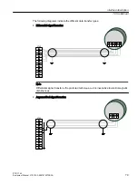
Страница 78: ...1 2B 2B Handwheel pulses track B channel 2 12 2B 2 B Handwheel pulses track B negated channel 2 Signal transfer Max two electronic handwheels can be connected to connector X143 on the rear of the PPU The signals can be transferred using the following technique Differential signal transfer RS422 One signal and a negated signal for each track Asymmetrical signal transfer One 5 V TTL signal for each ...

Страница 79: ...tial signal transfer 3 0 3 0 3 0 Note Differential signal transfer is the preferred technique as it is insensitive to electromagnetic disturbances Asymmetrical signal transfer 3 0 3 0 3 0 Interface description 7 6 Handwheel PPU 1740 Equipment Manual 01 2019 A5E47615272B AA 79 ...

Страница 80: ...pecification Feature Version Connector type 12 pin screw terminal Cable type Twisted pair shielded Max cable length 3 m Interface description 7 6 Handwheel PPU 1740 80 Equipment Manual 01 2019 A5E47615272B AA ...

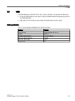
Страница 81: ...135 and X145 rear is enabled for USB devices and for service Cable specification The 5 V power supply is designed to be short circuit proof Features Variants Connector type Double USB socket type A Version USB 3 0 Current carrying capacity 0 9 A per channel Maximum data transfer rate 5 Gbit s Maximum cable length 3 m Power supply 5 V Interface description 7 7 USB PPU 1740 Equipment Manual 01 2019 ...

Страница 82: ...Interface description 7 7 USB PPU 1740 82 Equipment Manual 01 2019 A5E47615272B AA ...

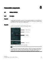
Страница 83: ...tains the following information RPSRQHQW QDPH 2UGHU QXPEHU QXPEHU YHUVLRQ 6HULDO QXPEHU Figure 8 1 Type plate using the NX10 3 as example Note You might need to access the information provided on the side mounted type plate after the equipment has been mounted Since the type plate is located on the right hand side of the housing which is the side typically used to connect to the SINAMICS S120 modu...

Страница 84: ...UIDFHV LJLWDO LQSXWV RXWSXWV OHFWURQLFV SRZHU VXSSO 5 6 7 EXWWRQ 7 7 7 0HDVXULQJ VRFNHWV URXQG FRQQHFWLRQ 0 1P 3URWHFWLYH FRQGXFWRU FRQQHFWLRQ 0 1P 6HULDO LQWHUIDFH QR IXQFWLRQ 7 SH SODWH V 6KLHOG FRQQHFWLRQ 5 3 Figure 8 2 Display of the NX module without cover Connectable components 8 1 NX10 3 NX15 3 PPU 1740 84 Equipment Manual 01 2019 A5E47615272B AA ...

Страница 85: ...d into the RAM Flashing 2 Hz Firmware CRC fault DP Off Electronics power supply outside permissible tolerance range The NX10 3 NX15 3 is not ready Green Continuous light CU_LINK is ready for communication and cyclic communication is running Flashing 0 5 Hz CU_LINK is ready for communication and cyclic communication is not running Red Continuous light At least one CU_LINK fault is present CU_LINK i...

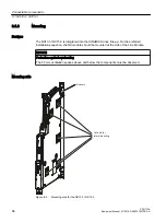
Страница 86: ... be mounted at the side of the Line Module NOTICE Protection against overheating The 80 mm ventilation spaces above and below the components must be observed Mounting aids 6SDFHUV XW RXWV IRU ODWHUDO PRXQWLQJ Figure 8 3 Mounting aids for the NX10 3 NX15 3 Connectable components 8 1 NX10 3 NX15 3 PPU 1740 86 Equipment Manual 01 2019 A5E47615272B AA ...

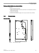
Страница 87: ...le The mounting fixtures fit exactly in the five cutouts on the NX 3 Push the two units together 4 Press down on the NX until it engages and is securely connected to the Line Module 8 1 4 Dimension drawing Dimension drawing Figure 8 4 Dimensions NX10 3 NX15 3 Connectable components 8 1 NX10 3 NX15 3 PPU 1740 Equipment Manual 01 2019 A5E47615272B AA 87 ...

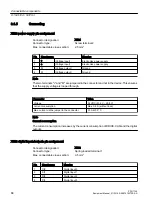
Страница 88: ...d through Parameter Value Voltage 24 VDC 20 4 V 28 8 V Current consumption Max 0 8 A without load Max current via the jumper in the connector 20 A at 55 C Note Current consumption The current consumption increases by the current consumption of DRIVE CLiQ and the digital outputs X122 digital inputs outputs pin assignment Connector designation X122 Connector type Spring loaded terminal 1 Max connect...

Страница 89: ...nnect the ground reference of the digital inputs Jumper to terminal M This removes the electrical isolation for these digital inputs Parameter Value Current consumption Typical 10 mA at 24 VDC Galvanic isolation The reference potential is terminal M1 As an input Voltage 3 V to 30 V Current consumption Typical 10 mA at 24 VDC Signal level including ripple High signal level 15 V to 30 V Low signal l...

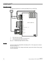
Страница 90: ...cal isolation for digital inputs DI 3 Can be parameterized as either input or output Figure 8 5 Connection example for the NX10 3 NX15 3 See also For the pin assignment of the DRIVE CLiQ interfaces X100 X103 please refer to Section DRIVE CLiQ Page 77 For further information on DC voltage and standards please refer to Section Power supply connection Page 65 Connectable components 8 1 NX10 3 NX15 3 ...

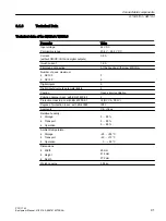
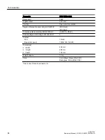
Страница 91: ...puts outputs parameterizable 4 Cooling Open circuit ventilation Pollution degree in acc with EN 61800 5 1 2 Protection class in acc with EN 61800 5 1 III DVC A PELV Degree of protection in acc with EN 60529 IP20 Approvals CE cULus Relative humidity Storage Transport Operation 5 95 5 95 5 95 Ambient temperature Storage Transport Operation 25 55 C 40 70 C 0 55 C Dimensions Width Height Depth 25 mm 4...

Страница 92: ...Connectable components 8 1 NX10 3 NX15 3 PPU 1740 92 Equipment Manual 01 2019 A5E47615272B AA ...

Страница 93: ...n class according to EN 61800 5 1 III DVC A PELV Pollution degree according to EN 61800 5 1 2 Display Size Resolution pixel 15 inch 1366x768 HD ready Dimensions Width Height Depth 398 mm 257 mm 138 mm Weight approx 6 1 kg Color Front Black Frame RAL 9017 Back glass Black RAL 9005 max current for each connector 1A PPU 1740 1900 Parameter PPU 17400 1900 Input voltage 24 VDC 20 15 20 4V 28 8V Rated c...

Страница 94: ...ss according to EN 61800 5 1 III DVC A PELV Pollution degree according to EN 61800 5 1 2 Display Size Resolution pixel 19 inch 1920x1080 full HD Dimensions Width Height Depth 464 mm 294 mm 138 mm Weight approx 7 3 kg Color Front Black Frame RAL 9017 Back glass Black RAL 9005 max current for each connector 1A Technical data PPU 1740 94 Equipment Manual 01 2019 A5E47615272B AA ...

Страница 95: ...elevant for SINUMERIK ONE devices European Machinery Directive SINUMERIK ONE devices fulfil the requirements stipulated in the European Machinery Directive 2006 42 EU insofar as they are covered by the application area of this directive However the use of the SINUMERIK ONE devices in a typical machine application has been fully assessed for compliance with the main regulations in this directive co...

Страница 96: ... death Only use power supplies that provide PELV Protective Extra Low Voltage output voltages acc to UL 61010 for all connections and terminals of the electronics modules EMC limit values in South Korea The EMC limit values to be observed for Korea correspond to the limit values of the EMC product standard for variable speed electric drives EN 61800 3 of category C2 or the limit value class A Grou...

Страница 97: ... Icon Meaning Ground e g M 24 V Connection for function potential bonding Connection for protective conductor Technical data 9 1 Relevant directives and standards PPU 1740 Equipment Manual 01 2019 A5E47615272B AA 97 ...

Страница 98: ...Technical data 9 1 Relevant directives and standards PPU 1740 98 Equipment Manual 01 2019 A5E47615272B AA ...

Страница 99: ...eel 5 V DC RS422 6FC9320 5DC01 Without front panel with small setting wheel5 V DC RS422 6FC9320 5DM00 Without front panel without setting wheel for installa tion 5 V DC RS422 6FC9320 5DF01 Portable in housing with setting wheel 5 V DC RS422spiral cable length 2 5 m 6FC9320 5DE02 Increased number of axes Numeric Control Extension NX10 3 6SL3040 1NC00 0AA0 Numeric Control Extension NX15 3 6SL3040 1N...

Страница 100: ...Spare parts and accessories PPU 1740 100 Equipment Manual 01 2019 A5E47615272B AA ...

Страница 101: ... DRIVE CLiQ Drive Component Link with IQ EMC Electromagnetic compatibility EN European standard ESD Electro Static Discharge elektrostatische Entladung GSM Global System for Mobile Communications Worldwide standard for wireless transmission of voice data fax and text messages SMS LEDs Light emitting diode light emitting diode display MAC Media Access Control MCP Machine control panel Machine contr...

Страница 102: ...Pulses per revolution SRAM Static Random Access Memory Static memory battery backed NV SRAM Non Volatile Static Random Access Memory Non volatile memory USB Universal Serial Bus Bus system for connecting additional devices to a computer VDE Association of Electrical Engineering Electronics and Information Technology Germany Appendix 11 1 Abbreviations PPU 1740 102 Equipment Manual 01 2019 A5E47615...

Страница 103: ...w 109768483 You can display documents or download them in PDF and HTML5 format The documentation is divided into the following categories User Operating User Programming Manufacturer Service Configuring Manufacturer Service Commissioning Manufacturer Service Functions Safety Integrated SINUMERIK Integrate MindApp Information and training Appendix 11 2 Documentation overview ONE PPU 1740 Equipment ...

Страница 104: ...Appendix 11 2 Documentation overview ONE PPU 1740 104 Equipment Manual 01 2019 A5E47615272B AA ...

Страница 105: ...VE CLiQ Interface 77 E Equipotential bonding connections 44 Ethernet 67 Pin assignment 68 F Finger gestures 35 Function impairing dust 48 G Grounding measures 43 I Industrial Ethernet 21 Installing PPU 56 Interface PROFINET 69 L LED displays Ethernet 68 PROFINET 69 License key 37 Line connection 43 Load operating system 31 M Maintenance Scope of maintenance 61 N NCK outputs 32 Noise immunity 44 NX...

Страница 106: ... card interface 37 Servo motor 21 Shielded signal cables 44 Signal cables 44 SIMOTICS S 21 SIMOTICS T 21 Smart Line Module Enabling signal 63 Spare parts 99 Status information 31 System configuration 40 2 auxiliary axes 41 6 axes and safety integrated 42 System error 32 T Technical data NX10 3 NX15 3 91 The NCK commissioning switch 33 Topology example 20 Torque motor 21 Type plate NX10 3 NX15 3 83...

Отзывы: