PROFIBUS DP Communication
8.1 General information
Manual
234
Commissioning Manual, 05/2008, 6FC5397–4CP10–4BA0
8.1.5
Networking rules
Basic rules
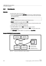
The following basic rules must be observed:
1.
The bus line must be terminated at both ends. For this purpose, enable the terminating
resistor in the PROFIBUS DP connector of the first and of the last nodes and disable the
remaining terminators.
NOTICE
Only two enabled terminating resistors are permitted per bus line.
2.
At least one termination must be supplied with 5 V.
To accomplish this, the PROFIBUS DP Connector with an activated terminating resistor
must be connected to a device that is switched on.
3.
No spur lines may be routed to the PROFIBUS DP.
4.
Each PROFIBUS DP node must first be connected and then enabled.
When a station is disconnected, the connection must first be deactivated and then the
connector is withdrawn.
5.
The cable length of a PROFIBUS DP bus segment may be max. 100 m.
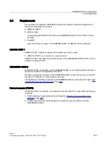
Example: PROFIBUS DP network installation
)LHOGGHYLFH
6,0$7,&(7
)LHOGGHYLFH
6,0$7,&(7
RII
RQ
RQ
RII
RII
'ULYH8QLW
6,1$0,&66
'ULYH8QLW
6,1$0,&66
RQ
RII
7HUPLQDWLQJUHVLVWRULQ
WKHFRQQHFWRUHQDEOHG
7HUPLQDWLQJUHVLVWRULQ
WKHFRQQHFWRUQRWHQDEOHG
6,180(5,.'LVO
3&8
0&,%RDUG
352),%86'3
PD[P
352),%86'3
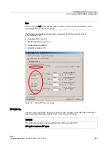
Figure 8-3
Example of a PROFIBUS DP network installation
Содержание SINUMERIK 840Di sl
Страница 118: ...Configuration 3 3 Connection overview Manual 118 Commissioning Manual 05 2008 6FC5397 4CP10 4BA0 ...
Страница 148: ...Power On and Power Up 5 7 License management Manual 148 Commissioning Manual 05 2008 6FC5397 4CP10 4BA0 ...
Страница 186: ...PLC commissioning 6 8 Load configuration in PG PLC STEP 7 Manual 186 Commissioning Manual 05 2008 6FC5397 4CP10 4BA0 ...
Страница 344: ...Drive commissioning SINAMICS 9 5 Basic principles Manual 344 Commissioning Manual 05 2008 6FC5397 4CP10 4BA0 ...
Страница 624: ...Glossary Manual 624 Commissioning Manual 05 2008 6FC5397 4CP10 4BA0 ...

