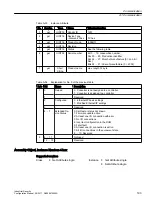
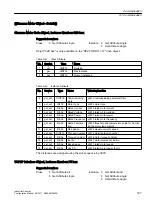
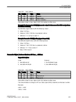

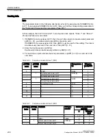


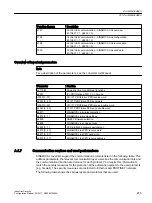
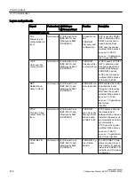


Corresponding parameters for IF1 or IF2
Use different parameters for configuring, depending on which interface SINAMICS Link is
assigned:
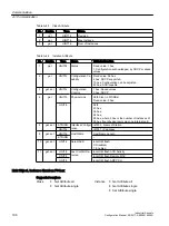
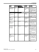
Table A-49
Corresponding parameters
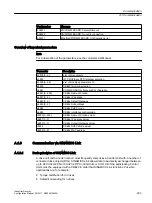
Parameters
IF1
IF2
Setting of the processing mode for PROFIdrive STW1.10 "Control by PLC".
p2037
p8837
Connector output to interconnect the PZD (setpoints) received from the
fieldbus controller in the word format.
r2050
r8850
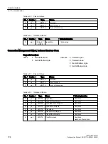
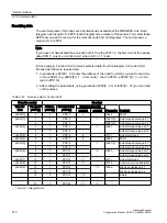
Selects the PZD (actual values) to be sent to the fieldbus controller in the
word format.
p2051
p8851
Displays the PZD (actual values) sent to the fieldbus controller in the word
format.
r2053
r8853
Connector output to interconnect the PZD (setpoints) received from the
fieldbus controller in the double word format.
r2060
r8860
Selects the PZD (actual values) to be sent to the fieldbus controller in the
double word format.
p2061
p8861
Displays the PZD (actual values) sent to the fieldbus controller in the dou‐
ble word format.
r2063
r8863
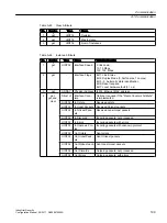
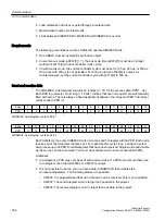
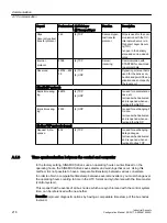
A.1.6.3
Configuring and commissioning
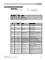
Commissioning
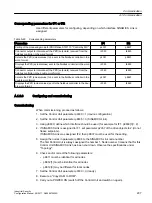
When commissioning, proceed as follows:
1. Set the Control Unit parameter p0009 = 1 (device configuration).
2. Set the Control Unit parameter p8835 = 3 (SINAMICS Link).
3. Using p8839, define which interface should be used (for example for IF1: p8839[0] = 2).
4. If SINAMICS Link is assigned to IF1, set parameter p2037 of the drive objects to 2 (do not
freeze setpoints).
If SINAMICS Link was assigned IF2, then p8837 must be used for the setting.
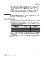
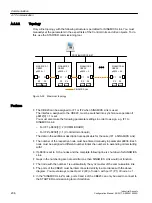
5. Assign the nodes in parameter p8836 to the SINAMICS Link node number.
The first Control Unit is always assigned the number 1. Node number 0 means that for this
Control Unit SINAMICS Link has been shut down. Observe the specifications under
"Topology".
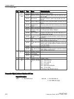
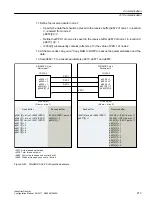
6. Check and/or correct the following parameters:
– p8811 must be identical for all nodes
– p8812[1] must be identical for all nodes
– p8812[0] may be different for local nodes
7. Set the Control Unit parameter p0009 = 0 (ready).
8. Execute a "Copy RAM to ROM".
9. Carry out a POWER ON (switch off the Control Unit and switch on again).
Communication
A.1 Communication
Industrial Security
Configuration Manual, 08/2017, A5E36912609A
207
Содержание SINAMICS
Страница 6: ...Table of contents Industrial Security 6 Configuration Manual 08 2017 A5E36912609A ...
Страница 8: ...Introduction Industrial Security 8 Configuration Manual 08 2017 A5E36912609A ...
Страница 18: ...Industrial Security 3 4 Security management Industrial Security 18 Configuration Manual 08 2017 A5E36912609A ...
Страница 222: ...Communication A 1 Communication Industrial Security 222 Configuration Manual 08 2017 A5E36912609A ...
Страница 224: ...Service Support Industrial Security 224 Configuration Manual 08 2017 A5E36912609A ...