background image

5.5

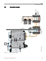
Connection example

'

LV

WUL

EX

WH

G

6

0

/

LQ

H

&

RQ

QH

FW

LR

Q

IR

UD

GG

LWL

RQ

DO

6

0

;

E

LG

LUH

FW

LR

QD

O,

2

V

;

%

UD

NH

UH

OH

DV

HG

IR

UV

HU

YL

FH

S

XU

SR

VH

V

5

HV

HU

YH

G

5

HV

HU

YH

G

+RX

VLQ

JS

DQH

O

(

[W

9

6F

KH

P

DW

LF

GL

DJ

UD

P

'

4

'

5

,9

(

&

/L

4

'

5

,9

(

&

/L

4

'

5

,9

(

&

/L

4

+\EULG&DEOH

;

;

0

;

;

;

;

'5

,9

(&

/L4

$

0

5'

<

0

7(0

3

'&

/,

1.

'

&

3

'

&

1

0

'

&

3

'

&

1

0

/L

QH

0

RG

XO

H

8

:


9

:

;

9

8

&

RQ

WUR

O

8

QL

W

/('

V

'

&

/

,1

.

5

(

$

'

<

0

'5

,9

(&

/L4

/('

V

'

&

/

,1

.

5

'

<

'&

3

'&

1

3(

0

'4

B6

+,(

/'

0

%5

B5

(/

(

$6

(

0

B(

;

7

3(

3

B

6(

1

62

5

'

,'

2

'

,'

2

0  3( '

&

1

'

&

3

0

;

;

+

\E

ULG

&

DE

OH

6

0

6

0

+

\E

ULG

&

DE

LQ

HW

%

XV

KL

QJ

2

SW

LR

QD

O

Figure 5-7

Connection example, S120M 

S120M

5.5 Connection example

Manual, 06/2019, 6SL3097-5AW00-0BP1

89

Содержание Sinamics S120M

Страница 1: ...Equipment Manual Distributed drive technology Edition www siemens com drives 06 2019 S120M SINAMICS ...

Страница 2: ......

Страница 3: ... Fundamental safety instructions 2 System overview 3 Adapter Module 600 4 S120M 5 DRIVE CLiQ Extension 6 Hybrid Cabinet Bushing 7 Control cabinet design 8 Service and maintenance 9 Appendix A SINAMICS S120 SINAMICS S120M Distributed Drive Technology ...

Страница 4: ... those who based on their training and experience are capable of identifying risks and avoiding potential hazards when working with these products systems Proper use of Siemens products Note the following WARNING Siemens products may only be used for the applications described in the catalog and in the relevant technical documentation If products and components from other manufacturers are used th...

Страница 5: ...6 2 4 Residual risks of power drive systems 28 3 System overview 31 3 1 Field of application 31 3 2 Platform Concept and Totally Integrated Automation 33 3 3 Introduction 35 3 4 SINAMICS S120 components 37 3 4 1 Component specification according to UL 39 3 4 2 Overview of Line Modules 44 3 4 3 Overview of Motor Modules 46 3 4 4 Overview of components for distributed drive technology 48 3 5 System ...

Страница 6: ...faces 87 5 5 Connection example 89 5 6 Meaning of the LEDs 91 5 7 Dimension drawings 92 5 8 Mounting 93 5 9 Technical data 96 5 10 Characteristics 98 5 10 1 Torque characteristics 98 5 10 2 Overload capability 103 5 10 3 Derating characteristics 104 5 11 Motor holding brake 106 5 11 1 Description 106 5 11 2 Connection at the S120M 106 6 DRIVE CLiQ Extension 109 6 1 Description 109 6 2 Safety instr...

Страница 7: ... 6 Hybrid Cable connection at DRIVE CLiQ Extension 144 8 4 7 Maximum cable length for distributed S120M drive technology 145 8 4 8 Connectable conductor cross sections for screw terminals 146 8 4 9 Routing cables in a damp environment 146 8 4 10 DRIVE CLiQ signal cables 147 8 5 Potential equalization 149 8 6 Layout of the components 150 8 6 1 General 150 8 6 2 Current carrying capacity of the DC l...

Страница 8: ... 9 3 1 Central components AM600 164 9 3 2 Distributed components 165 9 4 Recycling and disposal 166 A Appendix 167 A 1 List of abbreviations 167 A 2 Documentation overview 179 Index 181 Table of contents 6 Manual 06 2019 6SL3097 5AW00 0BP1 ...

Страница 9: ... other and can be easily integrated into your existing automation system With SINAMICS you are prepared for digitization You benefit from highly efficient engineering with a variety of tools for the entire product development and production process And you also save space in the control cabinet thanks to the integrated safety technology You can find additional information about SINAMICS at the fol...

Страница 10: ...ionality of the supplied drive system Extensions or changes made by the machine manufacturer must be documented by the machine manufacturer For reasons of clarity this documentation does not contain all of the detailed information on all of the product types and cannot take into consideration every conceivable type of installation operation and service maintenance Target group This documentation i...

Страница 11: ...nd search in manuals information Questions relating to the technical documentation Please send any questions about the technical documentation e g suggestions for improvement corrections to the following email address mailto docu motioncontrol siemens com FAQs You can find Frequently Asked Questions under Product Support https support industry siemens com cs de en ps faq Introduction 1 2 General i...

Страница 12: ...20 Equipment Manual for Chassis Power Units Liquid cooled SINAMICS S120 Equipment Manual water cooled chassis power units for common cooling circuits SINAMICS S120 Equipment Manual for Chassis Power Units Air cooled SINAMICS S120 Equipment Manual for AC Drives SINAMICS S120 Equipment Manual Combi SINAMICS S120M Equipment Manual Distributed Drive Technology SINAMICS HLA System Manual Hydraulic Driv...

Страница 13: ...Manual Drive Functions Hardware Manual Control Units and expansion components Control Units Option Boards Terminal Modules HUB Modules VSM10 Encoder system connection SINAMICS S120 Equipment Manual for Control Units and Supplementary System Components Booksize power units Line connection Line Modules Motor Modules DC link components Braking resistors Control cabinet design SINAMICS S120 Equipment ...

Страница 14: ...raining on products systems and solutions for automation and drives Technical Support Country specific telephone numbers for technical support are provided in the Internet at the following address https support industry siemens com cs ww en sc in the Contact area Introduction 1 5 Training and support 12 Manual 06 2019 6SL3097 5AW00 0BP1 ...

Страница 15: ...S devices fulfil the requirements stipulated in the Low Voltage Directive 2014 35 EU insofar as they are covered by the application area of this directive European Machinery Directive SINAMICS S devices fulfil the requirements stipulated in the Low Voltage Directive 2006 42 EU insofar as they are covered by the application area of this directive However the use of the SINAMICS S devices in a typic...

Страница 16: ...ory Certification SINAMICS S devices do not fall in the area of validity of the China Compulsory Certification CCC EMC limit values in South Korea The EMC limit values to be observed for Korea correspond to the limit values of the EMC product standard for variable speed electric drives EN 61800 3 of category C2 or the limit value class A Group 1 to KN11 By implementing appropriate additional measu...

Страница 17: ...t maintenance improvements to robustness discontinuations of components etc These further developments are spare parts compatible and do not change the article number In the scope of such spare parts compatible further developments connector connection positions are sometimes changed slightly This does not cause any problems with proper use of the components Please take this fact into consideratio...

Страница 18: ...ymbols Table 1 1 Symbols Icon Meaning Connection for protective conductor Ground e g M 24 V Connection for function potential bonding Introduction 1 7 Additional information 16 Manual 06 2019 6SL3097 5AW00 0BP1 ...

Страница 19: ...product does not process neither store any person related data only technical function data e g time stamps If the user links these data with other data e g shift plans or if he stores person related data on the same data medium e g hard disk thus personalizing these data he has to ensure compliance with the applicable data protection stipulations Introduction 1 8 General Data Protection Regulatio...

Страница 20: ...Introduction 1 8 General Data Protection Regulation 18 Manual 06 2019 6SL3097 5AW00 0BP1 ...

Страница 21: ...annot move 7 Identify all other dangerous energy sources e g compressed air hydraulic systems or water Switch the energy sources to a safe state 8 Check that the correct drive system is completely locked After you have completed the work restore the operational readiness in the inverse sequence WARNING Risk of electric shock and fire from supply networks with an excessively high impedance Excessiv...

Страница 22: ...liance with the applicable regulations WARNING Electric shock due to connection to an unsuitable power supply When equipment is connected to an unsuitable power supply exposed components may carry a hazardous voltage Contact with hazardous voltage can result in severe injury or death Only use power supplies that provide SELV Safety Extra Low Voltage or PELV Protective Extra Low Voltage output volt...

Страница 23: ...sult in death or serious injury Wait for 5 minutes before you check that the unit really is in a no voltage condition and start work NOTICE Property damage due to loose power connections Insufficient tightening torques or vibration can result in loose power connections This can result in damage due to fire device defects or malfunctions Tighten all power connections to the prescribed torque Check ...

Страница 24: ... Industry Online Support app only on equipment that has already been switched off NOTICE Damage to motor insulation due to excessive voltages When operated on systems with grounded line conductor or in the event of a ground fault in the IT system the motor insulation can be damaged by the higher voltage to ground If you use motors that have insulation that is not designed for operation with ground...

Страница 25: ... machine disconnect the devices as all converters and motors have been subject to a high voltage test by the manufacturer and therefore it is not necessary to perform an additional test within the system machine WARNING Unexpected movement of machines caused by inactive safety functions Inactive or non adapted safety functions can trigger unexpected machine movements that may result in serious inj...

Страница 26: ...ty Integrated functions If you want to use Safety Integrated functions you must observe the safety notices in the Safety Integrated manuals Fundamental safety instructions 2 1 General safety instructions 24 Manual 06 2019 6SL3097 5AW00 0BP1 ...

Страница 27: ...ck store transport and send electronic components modules or devices in their original packaging or in other suitable materials e g conductive foam rubber of aluminum foil Only touch components modules and devices when you are grounded by one of the following methods Wearing an ESD wrist strap Wearing ESD shoes or ESD grounding straps in ESD areas with conductive flooring Only place electronic com...

Страница 28: ...g firewalls and or network segmentation are in place For additional information on industrial security measures that can be implemented please visit Industrial Security http www siemens com industrialsecurity Siemens products and solutions undergo continuous development to make them more secure Siemens strongly recommends that product updates are applied as soon as they become available and that o...

Страница 29: ...trial security concept for the installation or machine Make sure that you include all installed products into the holistic industrial security concept Protect files stored on exchangeable storage media from malicious software by with suitable protection measures e g virus scanners On completion of commissioning check all security related settings Protect the drive against unauthorized changes by a...

Страница 30: ...usually high temperatures including open flames as well as emissions of light noise particles gases etc can occur inside and outside the components under fault conditions caused by for example Component malfunctions Software errors Operation and or environmental conditions outside the specifications External influences damage 3 Hazardous shock voltages caused by for example Component malfunctions ...

Страница 31: ...ut residual risks of the components in a drive system see the relevant sections in the technical user documentation Fundamental safety instructions 2 4 Residual risks of power drive systems Manual 06 2019 6SL3097 5AW00 0BP1 29 ...

Страница 32: ...Fundamental safety instructions 2 4 Residual risks of power drive systems 30 Manual 06 2019 6SL3097 5AW00 0BP1 ...

Страница 33: ...ors as well as conveyor and transport systems Drive line ups in textile plastic film and paper machines as well as in rolling mill plants High precision servo drives in the manufacture of wind turbines Highly dynamic servo drives for machine tools as well as packaging and printing machines 0L HUV PLOOV 3ODVWLF RQYHUWLQJ 3DFNDJLQJ 0DFKLQH WRROV 7H WLOHV 3ULQWLQJ PDFKLQHV RRGZRUNLQJ 5HQHZDEOH HQHUJL...

Страница 34: ...distributed servo drive technology S120M is a synchronous motor with integrated power unit which is connected to a central Control Unit via DRIVE CLiQ SINAMICS G is designed for standard applications with induction motors These applications have less stringent requirements regarding the dynamic performance of the motor speed SINAMICS V is designed to address applications where basic drive function...

Страница 35: ...nagement functions ensure consistent data and simplify archiving of the entire plant project From V14 the Startdrive commissioning tool is an integral element of the TIA platform SINAMICS S120 supports communication via PROFINET and PROFIBUS DP Communication via PROFINET This Ethernet based bus enables control data to be exchanged at high speed via PROFINET IO with IRT or RT and makes SINAMICS S12...

Страница 36: ...Figure 3 2 SINAMICS as part of the Siemens modular automation system System overview 3 2 Platform Concept and Totally Integrated Automation 34 Manual 06 2019 6SL3097 5AW00 0BP1 ...

Страница 37: ...RXEOH 0RWRU 0RGXOH 6LQJOH 0RWRU 0RGXOH GDSWHU 0RGXOH 9 9 EULG DEOH 6 0 RQWURO 6XSSO 0RGXOH Figure 3 3 System overview SINAMICS S120 with distributed servo drive technology S120M Modular system for sophisticated drive tasks SINAMICS S120 solves complex drive tasks for a wide range of industrial applications and is therefore designed as a modular system Select from many different harmonized componen...

Страница 38: ...gital interface between SINAMICS components The SINAMICS S120 components including the motors and encoders are interconnected via a joint serial interface called DRIVE CLiQ The standardized cables and connectors reduce the variety of different parts and cut storage costs Encoder evaluations for converting standard encoder signals to DRIVE CLiQ are available for third party motors or retrofit appli...

Страница 39: ...QHW EXVKLQJV FRXSOLQJ EULG DEOH EULG DELQHW XVKLQJ KDVVLV KDVVLV RRNVL H RRNVL H RPSDFW RRNVL H RRNVL H RPSDFW KDVVLV ORFNVL H 9ROWDJH 3URWHFWLRQ 0RGXOH 3RZHU 0RGXOHV GDSWHU 0RGXOH 6 0 LQH 0RGXOHV RPEL 0RWRU 0RGXOHV UDNLQJ 0RGXOHV RRNVL H KDVVLV 6HQVRU 0RGXOHV RQWURO 6XSSO 0RGXOH DSDFLWRU 0RGXOH 6LQJOH 0RWRU 0RGXOHV RXEOH 0RWRU 0RGXOHV 5 9 L4 WHQVLRQ RQWURO 8QLWV 8 8 RQWURO 8QLW GDSWHU 8 8 DVLF 2S...

Страница 40: ... handle simple installation and wiring Practical connection system cable routing in accordance with EMC requirements Standardized design side by side mounting Booksize format Booksize format units are optimized for multi axis applications and are mounted adjacent to one another The connection for the shared voltage source DC link is an integral feature The booksize format offers various cooling op...

Страница 41: ...If the components are operating in the range between 40 C and 55 C the linear reductions of the output currents or output powers to 60 should be used Note Connection to line supply systems S120M components are only suitable for direct connection to line supplies with a grounded neutral point Note Using the 24 V terminal adapter When using the 24 V terminal adapter Page 131 only use wires with a te...

Страница 42: ... 000 3 000 3 000 3 000 3 000 Rated torque Nm lbf in 0 8 7 08 1 05 9 29 1 8 15 9 2 7 23 9 2 2 19 5 Motor insulation system Class F 155 Enclosure type Type 1 DC link voltage VDC 510 700 DC link supply Max input output current current passed through from X1 to X2 ADC 20 Max input current current con sumption under normal operation ADC 1 13 1 7 1 6 1 5 1 7 Electronics power supply VDC 48 Electronics s...

Страница 43: ... 0 52 0 54 0 54 Signal interface X3 Output voltage VDC 24 Max output current terminal 1 ADC 0 1 Max output current terminal 2 re sistive ADC 0 1 Max output current terminal 3 re sistive ADC 0 1 Max total output current ADC 0 2 The S120M modules provide motor overload protection at a level of 125 of the nominal motor current For the North American market For the brake release on connector X4 connec...

Страница 44: ...ble Unit 6FX8002 7HY Max cable temperature C 80 Electronics power supply Voltage Current Wire cross section VDC ADC mm2 AWG 48 10 2 5 14 DC link supply grounding Voltage Current Wire cross section VDC ADC mm2 AWG 720 20 4 12 Signal cores Voltage Current Wire cross section VDC ADC mm2 AWG 30 1 0 34 22 To connect the distributed components HCB DQE and S120M with one another and to the AM 600 it is o...

Страница 45: ...oksize with 120 kW power is not certified Table 3 8 Basic Line Modules booksize Heat dissipation 20 kW 40 kW Internal air cooling 6SL3130 1TE22 0A 1TE24 0A Cold plate cooling 6SL3136 Operation of the components of the SINAMICS S120M system on Basic Line Modules Booksize with 100 kW power is not certified Table 3 9 Smart Line Modules booksize Heat dissipation 5 kW 10 kW 16 kW 36 kW 55 kW Internal a...

Страница 46: ...nt Manual Booksize Power Units Note The SINAMICS S120M Modular Drive System is intended for use only in industrial machinery NFPA 79 applications on the North American market 3 4 2 Overview of Line Modules Line Modules generate a DC voltage in the DC link from the three phase line voltage that supplies the connected Motor Modules with power All Basic Line Modules and Active Line Modules as well as...

Страница 47: ...s Supply voltage 3 AC 380 V 10 15 1 min to 3 AC 480 V 10 47 to 63 Hz Suitable for TN TT and IT supply systems Internal or external air cooling Liquid cooling and cold plate cooling Short circuit and ground fault proof during the precharging phase Integrated DC link and electronics current busbar connection LEDs for indicating statuses and for diagnostics System overview 3 4 SINAMICS S120 component...

Страница 48: ... kW to 55 kW Smart Line Modules outgoing circuit for DC link busbar possible on both sides Characteristics of the Basic Line Modules Unregulated DC link voltage No regenerative feedback capability For all Basic Line Modules an outgoing circuit for DC link busbar is possible on both sides 3 4 3 Overview of Motor Modules The Motor Modules in the SINAMICS S system in booksize format are implemented a...

Страница 49: ... Motor Modules Single type from 3 A to 200 A Double type from 1 7 A to 18 A Internal external air cooling Liquid cooling and cold plate cooling Short circuit ground fault proof Integrated DC link and electronics current busbar connection Integrated safety motor braking control Electronic rating plate System overview 3 4 SINAMICS S120 components Manual 06 2019 6SL3097 5AW00 0BP1 47 ...

Страница 50: ...supply or from a Control Supply Module CSM The supply can also be taken from the central drive line up using the 24 V terminal connector Use of the Line Modules ALM BLM or SLM from the SINAMICS S120 product family The Adapter Module 600 opens a line of distributed S120M drives It feeds the DC link auxiliary voltage and DRIVE CLiQ in a hybrid cable If you want to operate several S120M drives the nu...

Страница 51: ... EULG FDEOH 9 DX LOLDU YROWDJH 5 9 L4 7HUPLQDWLQJ FRQQHFWRU LVWULEXWHG FRPSRQHQWV FRQQHFWLRQ H DPSOH HQWUDO FRPSRQHQWV EULG DELQHW XVKLQJ RQWURO 8QLW RQWURO 8QLW 6 0 6 0 6 0 6 0 6 0 6 0 6 0 6 0 6 0 5 9 L4 5 9 L4 WHQVLRQ 5 9 L4 6 723 9 0 0 6 0 0 Figure 3 7 Principle of an S120M topology S120M Safety Integrated concept Safety Integrated functions can be controlled with PROFIsafe or TM54F System over...

Страница 52: ...ting actuators and sensors to the S120M X4 Connection to externally open a holding brake LEDs Display of operating states DRIVE CLiQ Extension X1 IN Hybrid connector X2 OUT Hybrid connector X200 DRIVE CLiQ Hybrid Cabinet Bushing X1 IN Hybrid connector X2 OUT Hybrid connector X201 IN DRIVE CLiQ X202 OUT DRIVE CLiQ System overview 3 4 SINAMICS S120 components 50 Manual 06 2019 6SL3097 5AW00 0BP1 ...

Страница 53: ...l components Category C2 is possible Overvoltage category III to EN 61800 5 1 Degree of contamination 2 acc to EN 61800 5 1 for S120 and S120M central components 3 acc to EN 61800 5 1 for S120M distributed components Table 3 12 Degree of protection and safety class Degree of protection The central components SINAMICS S120 Booksize and AM600 Distributed components S120M IP20 or IPXXB acc to IEC 605...

Страница 54: ...tions Long term storage Transport Operation for SINAMICS S120 and AM600 central components Operation for SINAMICS S120M distributed components Class 1K4 according to EN 60721 3 1 in product packaging1 Temperature 25 55 C Class 2K4 according to EN 60721 3 2 in transport packaging2 Temperature 40 70 C Class 3K3 according to EN 60721 3 3 with increased ruggedness with respect to relative humidity Tem...

Страница 55: ...itable for transport or secondary packaging which together with the product packaging satisfies the requirements for transport Table 3 14 Certificates Certificates Declarations of Conformity CE Approvals ULus cULus Note Radio service interference due to radio disturbances in residential environments In a residential environment this product can cause radio disturbances which may make interference ...

Страница 56: ...System overview 3 5 System Data 54 Manual 06 2019 6SL3097 5AW00 0BP1 ...

Страница 57: ...select a suitable Line Module with the necessary infeed power NOTICE Equipment damage due to overload of the 24 V busbar At maximum load the AM600 may only be mounted on the right hand edge of the line up Otherwise an overload of the 24 V busbar and equipment damage may occur At maximum load mount the AM600 on the right hand edge of the line up Establish the 24 V power supply of the AM600 via an e...

Страница 58: ...e central power infeed via the Line Module Cooling methods The AM600 has internal air cooling Identification at DRIVE CLiQ The AM600 is not an active DRIVE CLiQ node The AM600 only feeds into one DRIVE CLiQ line in the hybrid cable Adapter Module 600 4 1 Description 56 Manual 06 2019 6SL3097 5AW00 0BP1 ...

Страница 59: ...rnal protective conductor satisfies at least one of the following conditions It has been laid so that it is protected against mechanical damage 1 If it is a single cable it has a cross section of at least 10 mm Cu If it is a conductor of a multi conductor cable it has a cross section of at least 2 5 mm Cu It has a second protective conductor in parallel with the same cross section It complies with...

Страница 60: ... side covers article number 6SL3162 5AA00 0AA0 NOTICE Damage caused by the use of incorrect DRIVE CLiQ cables Damage or malfunctions can occur on the devices or system if incorrect or unapproved DRIVE CLiQ cables or hybrid cables are used Only use suitable DRIVE CLiQ cables and hybrid cables that have been approved by Siemens for the respective application Adapter Module 600 4 2 Safety instruction...

Страница 61: ...RQLFV SRZHU VXSSO OLQN EXVEDUV 3URWHFWLYH FRQGXFWRU FRQQHFWLRQ 0 1P 9 WHUPLQDO DGDSWHU 7HUPLQDO 6HUYLFLQJ RSHQLQJ IRU IXVHV DQG IDQV V EULG DEOH 1P 5 9 L4 Figure 4 1 Adapter Module 600 AM600 Adapter Module 600 4 3 Interface description Manual 06 2019 6SL3097 5AW00 0BP1 59 ...

Страница 62: ...ive data 5 Protective conductor 6 M Electronics ground 7 48 V power supply 8 DCN DC link voltage M600 9 DCP DC link voltage P600 DQ_SHIELD Shield Note Mounting the hybrid connector You can screw on the hybrid connector by hand For operation tighten it with an Allen key 3 0 Nm 26 6 lbf in Adapter Module 600 4 3 Interface description 60 Manual 06 2019 6SL3097 5AW00 0BP1 ...

Страница 63: ...ssible amount the drive train of the S120M system is shut down in a controlled way The RDY signal displays the fault during shutdown 2 DC LINK Notification DC link voltage is present at the distributed line Output referred to 24 V electronics ground Current carrying capacity 100 mA short circuit proof Meaning The terminal has 0 V if the DC link voltage is 50 V Note Hazardous DC link voltages may b...

Страница 64: ...data 1 TXP Transmit data 2 TXN Transmit data 3 RXP Receive data 4 Reserved do not use 5 Reserved do not use 6 RXN Receive data 7 Reserved do not use 8 Reserved do not use A Reserved do not use B Reserved do not use Adapter Module 600 4 3 Interface description 62 Manual 06 2019 6SL3097 5AW00 0BP1 ...

Страница 65: ...0 H W 9 1 The line supply connection must always be available 2 DI DO controlled by the Control Unit 3 No additional load permitted downstream of line contactor 4 The current carrying capacity of the DO must be observed an output interface may have to be used 5 Contact established via rear mounting panel or shielding buses in accordance with the EMC installation guideline Figure 4 2 Connection exa...

Страница 66: ...3 0 0 5 9 L4 DEOH 7 3 7 1 5 3 5 1 4B6 RQWURO 8QLW 8 3 0 0 0 0 9 0 0 2 2 2 2 0 0 3RUW 5 9 L4 3RUW 5 9 L4 3RUW 5 9 L4 3RUW 5 9 L4 352 86 2SWLRQ ERDUG 1 0 0 0 0 0 0 0 0 GDSWHU 0RGXOH Figure 4 3 Connection example AM600 X21 operating states at the Control Unit CU320 2 DP schematic Adapter Module 600 4 4 Connection example 64 Manual 06 2019 6SL3097 5AW00 0BP1 ...

Страница 67: ... drive line with 48 V DC is operating correctly without fault 48 V DC is available at the line Orange The DC link voltage is available at the AM600 output Off Cable protection fuses have ruptured DC link voltage can be present at the busbars of the AM600 Orange Overtemperature alarm or overtemperature fault with shutdown saved after 5 K overtemperature alarm Red Overcurrent trip or undefined DC li...

Страница 68: ...4 6 Dimension drawing Figure 4 4 Dimension drawing Adapter Module 600 AM600 all data in mm or inch Adapter Module 600 4 6 Dimension drawing 66 Manual 06 2019 6SL3097 5AW00 0BP1 ...

Страница 69: ...ndard Mounting an AM600 with internal air cooling Control cabinet panel mounting panel M6 studs M6 nut Spring washer Washer Figure 4 5 Mounting an AM600 with internal cooling Adapter Module 600 4 7 Mounting Manual 06 2019 6SL3097 5AW00 0BP1 67 ...

Страница 70: ... 1CC00 0AA0 This means that you can directly combine the AM600 with SINAMICS components in booksize format with internal air cooling Table 4 5 Number of spacing bolts and holes for the AM600 Module width in mm Number of spacing bolts Number of holes press in nuts 75 4 4 Preparing the mounting panel Inserting M6 press in nuts into the mounting panel Distance 25 mm 0 15 mm for module width 75 mm M6 ...

Страница 71: ...l Figure 4 7 Mounting an Adapter Module 600 with spacing bolts Tightening torque 6 Nm 53 1 lbf in As an alternative to press in nuts you can secure spacing bolts with M6 nuts at the rear of the mounting panel Adapter Module 600 4 7 Mounting Manual 06 2019 6SL3097 5AW00 0BP1 69 ...

Страница 72: ...istance 25 mm 0 15 mm for module width 75 mm Spacing bolt M6 nuts Mounting panel Figure 4 8 Installing the spacing bolts with M6 nuts on the rear of the mounting panel Tightening torque 6 Nm 53 1 lbf in Adapter Module 600 4 7 Mounting 70 Manual 06 2019 6SL3097 5AW00 0BP1 ...

Страница 73: ...or all components that are 75 mm wide or wider the DC link bridges must not be moved to the left or removed NOTICE Damage due to unsuitable screws The use of unsuitable screws for fastening the DC link busbars can cause damage Only use the original M4x16 screws on the left hand side Only use the original M4x20 screws on the right hand side The connection of a Line Module to a Motor Module is shown...

Страница 74: ...k busbars Connection of the 24 V busbars The 24 V busbars of the components are connected using the 24 V connectors in the accessories pack A 24 V connector must be plugged onto the 24 V busbars between the Line Module Motor Module and DC link component The 24 V connectors must be attached before the drive line up is commissioned Working steps 1 Place the 24 V connectors on to the 24 V busbars 2 P...

Страница 75: ...evere injury or death Only connect or disconnect the connections in a no voltage state Only remove the 24 V terminal adapter vertically in relation to the front plate Disconnect and connect the connections a maximum of 5 times in a row Note DRIVE CLiQ socket X201 on the upper side of the module Establish the connection to the Control Unit using a DRIVE CLiQ cable 4 pole terminal strip X21 on the u...

Страница 76: ...link voltage Output current In Base load current Ibase S6 current IS6 40 Peak current Imax DC link capacitance Current carrying capacity of the DC link busbar VDC Arms Arms Arms Arms μF ADC 510 720 25 0 21 3 30 0 50 0 705 20 100 Rated electrical power for a DC link voltage 600 VDC kW 14 70 Total power loss including electronic losses W 60 Minimum cable length to the 1st axis m 3 Ventilation cleara...

Страница 77: ...arrying capacity of the 24 V busbar max 20 A An additional 24 VDC feed is also possible via the 24 V terminal adapter If the components are operated at increased ambient temperatures 40 to 55 C then the DC link current and the electronic power supply must be appropriately reduced 3HUPLVVLEOH RXWSXW FXUUHQW PELHQW WHPSHUDWXUH r Figure 4 11 Output current as a function of the ambient temperature Ada...

Страница 78: ...ve and the line length connected It is determined using the SIZER for SIEMENS Drives engineering tool or it can be taken from the following diagram LQH OLQH OHQJWK ZLWK 6 0 ZLWK 6 0 ZLWK 6 0 DYDLODEOH SRZHU 3 LQH DYDLODEOH SRZHU 9 WR 6 0 FRPSRQHQWV P Figure 4 12 Dimensioning the power supply Dimensioning using the diagram Pline PN Lline LSegment i e the sum of the segment lengths between the AM600...

Страница 79: ...CS S120 central system via a hybrid cable with integrated DRIVE CLiQ via the Adapter Module 600 A central Control Unit is used for the closed loop control S120M is based on the 1FK7 synchronous motor and therefore has its most important properties These are Radial eccentricity concentricity axial eccentricity Maximum mechanical speeds Torque ripple Balancing Shaft Flange Note Motors on the convert...

Страница 80: ...ductor Touching conductive parts when the protective conductor is interrupted can result in death or serious injury Ensure that the following protective conductor connection paths are available Via the hybrid cable Via the protective conductor connection In this case the protective conductor cross section must be 4 mm2 Each of these connections must be suitable as a protective connection WARNING E...

Страница 81: ...lfunctions can occur on the devices or system when incorrect or unapproved DRIVE CLiQ cables are used Only use suitable hybrid cables which have been approved by Siemens for connecting the S120M S120M 5 2 Safety instructions for S120M Manual 06 2019 6SL3097 5AW00 0BP1 79 ...

Страница 82: ...g of the shaft outlet against splashwater or coolant Dry running of the radial shaft sealing ring is permissible Service life Approx 25000 h nominal value It is not permissible for liquid to collect in the flange IP67 Radial shaft sealing ring Version shaft outlet flange IP67 optional For gearbox mounting for gearboxes that are not sealed to seal against oil The sealing lip must be adequately cool...

Страница 83: ...int of application of force FRAS and the shaft shoulder in mm Figure 5 1 Force application point at the DE Maximum permissible radial force on the S120M 3HUPLVVLEOH UDGLDO IRUFH DW WKH VKDIW 1 5 6 Q PLQ Q PLQ Q PLQ Q PLQ Q PLQ Q PLQ Q PLQ Q PLQ Q PLQ PP Figure 5 2 Maximum permissible radial force at S120M SH36 article number 6SL3532 6DF71 S120M 5 3 Mechanical properties Manual 06 2019 6SL3097 5AW0...

Страница 84: ...um permissible radial force at S120M SH48 article number 6SL354 6DF71 Q PLQ Q PLQ Q PLQ Q PLQ Q PLQ Q PLQ PP 1 5 6 Figure 5 4 Maximum permissible radial force at S120M SH63 article number 6SL356 6DF71 S120M 5 3 Mechanical properties 82 Manual 06 2019 6SL3097 5AW00 0BP1 ...

Страница 85: ...3 approx 0 35 mm An axial force as large as the spring loading is not permitted 100 500 N Premature failure is the result when the bearing is not pre tensioned Calculating the permissible axial force FA FRAS 0 35 NOTICE Damage due to axial forces on the S120M with holding brake On an S120M with integrated permanent magnet excited holding brake axial forces at the shaft extension can cause damage T...

Страница 86: ...connection M5 3 Nm 26 6 lbf in Figure 5 5 Design and interface overview S120M Shaft and flange The specifications particularly for the centering distance and hole circle correspond to those of the 1FK7 motor series Just same as for the 1FK7 motor series the shaft extension is available with or without keyway S120M 5 4 Interface description 84 Manual 06 2019 6SL3097 5AW00 0BP1 ...

Страница 87: ...ive conductor X3 M12 socket Connection for sensors and actuators X4 M12 socket Connection is to externally release the holding brake X4 has no function for motors without integrated holding brake M5 female thread Protective conductor connection 3 Nm 26 6 lbf in READY DC LINK LEDs Display of operating states and or diagnostics S120M 5 4 Interface description Manual 06 2019 6SL3097 5AW00 0BP1 85 ...

Страница 88: ...RXN Receive data 5 Protective conductor 6 M Electronics ground 7 48 V DC power supply 8 DCN DC link voltage M600 9 DCP DC link voltage P600 DQ_SHIELD Shield Note Mounting the hybrid connector You can screw on the hybrid connector by hand For operation tighten it with an Allen key 3 0 Nm 26 6 lbf in S120M 5 4 Interface description 86 Manual 06 2019 6SL3097 5AW00 0BP1 ...

Страница 89: ...he DOs it is not permissible that the sensor supply is used 1 x DI 1 x DO 100 mA sensor power supply and 100 mA for DO M_EXT is the ground at the DI It is functionally isolated To increase the inter ference resistance we recommend connecting to grounding 2 DI DO 0 3 M_EXT 4 DI DO 1 5 1 P24_SENSOR 24 V external power supply DI DO bidirectional digital input output M_EXT Electronics ground Protectiv...

Страница 90: ...y voltage external 4 Reserved not used Note The X4 interface has no function on S120M motors without holding brakes Note Cable lengths at X3 X4 Maximum cable length 30 m each Note Releasing the motor holding brake using X4 For the function of interface X4 refer to the chapter Motor holding brake Connection to S120M Page 106 S120M 5 4 Interface description 88 Manual 06 2019 6SL3097 5AW00 0BP1 ...

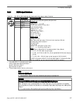
Страница 91: ...J SDQHO W 9 6FKHPDWLF GLDJUDP 4 5 9 L4 5 9 L4 5 9 L4 EULG DEOH 0 5 9 L4 0 5 0 7 03 1 3 1 0 3 1 0 LQH 0RGXOH 8 9 9 8 RQWURO 8QLW V 1 5 0 5 9 L4 V 1 5 3 1 3 0 4B6 0 5B5 6 0B 7 3 3 B6 1625 2 2 0 3 1 3 0 EULG DEOH 6 0 6 0 EULG DELQHW XVKLQJ 2SWLRQDO Figure 5 7 Connection example S120M S120M 5 5 Connection example Manual 06 2019 6SL3097 5AW00 0BP1 89 ...

Страница 92: ...HG 5HVHUYHG 7HUPLQDWLQJ FRQQHFWRU 6FKHPDWLF GLDJUDP 4 4 4 4 4 4 3 3 4 5 0 7 03 1 0 0 0 EULG DEOH 0 RQWURO 8QLW LQH 0RGXOH 3 1 0 EULG DEOH 0B 7 3 2 3 B6 1625 2 6 0 EULG DEOH 6 0 0B 7 3 2 3 B6 1625 2 1 287 5 9 L4 5 9 L4 WHQVLRQ EULG DEOH 0B 7 3 2 3 B6 1625 2 6 0 EULG DEOH 6 0 Q 0B 7 3 2 3 B6 1625 2 RQWURO 8QLW 0 5B5 6 0 5B5 6 0 5B5 6 0 5B5 6 3 1 0 3 1 0 H W 9 Figure 5 8 Connection example for S120M ...

Страница 93: ...ast one fault is present in this component power unit encoder Please observe The LED is activated regardless of whether the corre sponding messages have been reconfigured Remedy and acknowledge fault Green red 0 5 Hz Firmware is being downloaded Green red 2 Hz Firmware download is complete Wait for POWER ON Execute POWER ON Green orange or Red orange Component recognition via LED is activated p012...

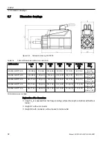
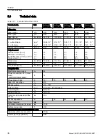
Страница 94: ...7 6SL3542 6DF71 0R 280 11 02 102 4 02 155 6 1 205 8 07 96 3 78 80 3 15 19 x 40 0 75 x 1 57 6SL3562 6DF71 0R 270 10 63 126 4 96 185 7 28 240 9 45 126 4 96 110 4 33 24 x 50 0 94 x 1 97 6SL3563 6DF71 0R 290 11 42 126 4 96 185 7 28 240 9 45 126 4 96 110 4 33 24 x 50 0 94 x 1 97 All dimensions are rounded Explanation of the dimensions Length LG is measured from the flange locating surface the length is...

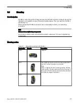
Страница 95: ...m of three sides of the S120M maintain a clearance 100 mm to neighboring components Mounting position Table 5 7 Designation according to IEC 60034 7 Designation Graphic Description IM B5 Standard IM V1 The S120M can also be used in mounting positions IM V1 and IM V3 without requiring a special order Note When configuring the IM V3 mounting position attention must be paid to the permissible axial f...

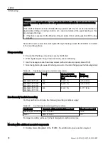
Страница 96: ... Note the tightening torques of the fixing screws for the motor flange see the following table Table 5 8 Tightening torques for electrical connections Article number Screw Washer ISO 7092 d2 outer diameter mm Torque Nm lbf in 6SL3532 6DF71 0R M6 6 d2 11 8 70 8 lbf in 6SL3540 6DF71 0R 6SL3542 6DF71 0R M6 6 d2 11 8 70 8 lbf in 6SL3562 6DF71 0R 6SL3563 6DF71 0R M8 8 d2 15 20 177 lbf in Non thermally ...

Страница 97: ...evelopment of heat also changes depending on the gearbox type To avoid thermally overloading motors when using gearboxes reduce the specified power data when designing the system see schematic diagram below QRQ LQVXODWHG GHVLJQ ZLWK JHDUER ZLWKRXW JHDUER LQVXODWHG GHVLJQ Q 0 Figure 5 10 Effect of the mounting conditions on the S1 characteristic S120M 5 8 Mounting Manual 06 2019 6SL3097 5AW00 0BP1 ...

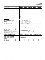
Страница 98: ...7 1 3 2 5 7 7 1 4 1 1 2 0 7 6 1 9 1 4 2 8 14 0 2 0 1 5 2 9 21 0 Static torque Nm lbf in 1 0 8 85 1 3 11 5 2 5 22 1 5 0 44 3 7 1 62 8 Stall current A 1 4 1 9 1 8 3 15 5 0 Torque maximum Nm lbf in 3 0 26 6 4 9 43 4 10 0 88 5 19 3 170 8 27 0 239 0 Converter data Electronics power supply VDC 48 Power consumption 48 V maxi mum electronics power supply W 12 Power drawn brake W 10 15 15 20 20 Rated DC li...

Страница 99: ...z mm g Class 3M3 according to EN 60721 3 3 With constant deflection 1 5 With constant acceleration 0 5 Shock test in operation Peak acceleration Shock duration g ms Class 3M3 according to EN 60721 3 3 7 22 Cooling method Via A flange and surface convection Sound pressure level acc to DIN EN ISO 1680 max tolerance 3 dB A dB A 55 55 55 65 65 Non thermally insulated mounting insulated mounting See Ch...

Страница 100: ...BLM SLM 400 V line supply DC link voltage 540 V DC Figure 5 11 Torque characteristics S120M on 400 V line supply for SH36 6SL3532 6DF71 0R Q PLQ 0 1P 6 0 6 6 6 6 0BPD 6 SINAMICS ALM 480 V line supply DC link voltage 720 V DC SINAMICS BLM SLM 480 V line supply DC link voltage 650 V DC S120M 5 10 Characteristics 98 Manual 06 2019 6SL3097 5AW00 0BP1 ...

Страница 101: ...DC SINAMICS BLM SLM 400 V line supply DC link voltage 540 V DC Figure 5 13 Torque characteristics S120M on 400 V line supply for SH48 6SL3540 6DF71 0R 6 0 6 5 0BPD 6 6 6 6 P 1 0 Q PLQ SINAMICS ALM 480 V line supply DC link voltage 720 V DC SINAMICS BLM SLM 480 V line supply DC link voltage 650 V DC Figure 5 14 Torque characteristics S120M on 480 V line supply for SH48 6SL3540 6DF71 0R S120M 5 10 C...

Страница 102: ...characteristics S120M on 400 V line supply for SH48 6SL3542 6DF71 0R 6 0 6 5 0BPD 6 6 6 6 Q PLQ P 1 0 SINAMICS ALM 480 V line supply DC link voltage 720 V DC SINAMICS BLM SLM 480 V line supply DC link voltage 650 V DC Figure 5 16 Torque characteristics S120M on 480 V line supply for SH48 6SL3542 6DF71 0R S120M 5 10 Characteristics 100 Manual 06 2019 6SL3097 5AW00 0BP1 ...

Страница 103: ...ue characteristics S120M on 400 V line supply for SH63 6SL3562 6DF71 0R 0 1P Q PLQ 0BPD 6 6 6 6 0 6 SINAMICS ALM 480 V line supply 720 V DC link voltage SINAMICS BLM SLM 480 V line supply DC link voltage 650 V DC Figure 5 18 Torque characteristics S120M on 480 V line supply for SH63 6SL3562 6DF71 0R S120M 5 10 Characteristics Manual 06 2019 6SL3097 5AW00 0BP1 101 ...

Страница 104: ...e supply for SH63 6SL3563 6DF71 0R 6 0 6 6 6 6 0BPD Q PLQ 0 1P 0B6S U SINAMICS ALM 480 V line supply 720 V DC link voltage SINAMICS BLM SLM 480 V line supply DC link voltage 650 V DC Figure 5 20 Torque characteristics S120M on 480 V line supply for SH63 6SL3563 6DF71 0R Note S3 operation The duty cycle duration for S3 operation is 10 s S120M 5 10 Characteristics 102 Manual 06 2019 6SL3097 5AW00 0B...

Страница 105: ...ineering software to select a suitable S120M See SIZER http support automation siemens com WW view de 10804987 130000 XW F FOH ZLWKRXW EDVH ORDG XW F FOH ZLWK EDVH ORDG Q V V Q Q V V Q W W Figure 5 21 Duty cycle 2 x Irated with without base load for servo drive Q PLQ PLQ 6 Q PD W Figure 5 22 Duty cycle IS6 with base load Q Q V V V Q W Figure 5 23 Duty cycle 2 x Irated with base load for servo driv...

Страница 106: ...se load 5 10 3 Derating characteristics For SINAMICS the rated data is only applicable for a specified range Outside this range certain performance data are restricted For SINAMICS systems there are constraints regarding the ambient temperature pulse frequency and installation altitude for example The following derating characteristics apply for the S120M S120M 5 10 Characteristics 104 Manual 06 2...

Страница 107: ...temperatures between 40 C and 55 C the static torque must be reduced according to the diagram above Derating must be moved on the basis of the static torque in the form of a parallel movement of the torque characteristic see the schematic diagram below 6 IRU r r 6 IRU r 7RUTXH 6SHHG Figure 5 28 Schematic diagram for torque rating as a function of the ambient temperature S120M 5 10 Characteristics ...

Страница 108: ... of the S120M The length of the S120M does not depend on whether there is a holding brake The holding brake is a brake equipped with permanent magnets The magnetic field of the permanent magnets results in a pulling force on the brake armature disk This means that in the no current condition the brake is closed and the motor shaft is held When the rated voltage is connected to the brake the soleno...

Страница 109: ... the supply voltage via the hybrid cable X4 is a commissioning interface Interface X4 must not be used in normal operation Cover the X4 interface with the protective cap supplied Table 5 11 X4 M12 socket external brake socket D coded Terminal Signal name Meaning 1 BR_RELEASE Brake supply voltage external 24 VDC 10 protective class III 2 Reserved not used 3 M Ground brake supply voltage external 4 ...

Страница 110: ...S120M 5 11 Motor holding brake 108 Manual 06 2019 6SL3097 5AW00 0BP1 ...

Страница 111: ...ontrol signals are fed to the line using DRIVE CLiQ via a DRIVE CLiQ Extension DRIVE CLiQ Extension without hybrid connector DRIVE CLiQ Extension with hybrid connector DRIVE CLiQ Extension includes One input socket for DRIVE CLiQ One input socket for the connection with Hybrid Cable from the previous S120M One output socket for the connection with Hybrid Cable to the following S120M Manual 06 2019...

Страница 112: ...in a voltage free state by measuring at the DC link terminals DCP and DCN NOTICE Damage through use of incorrect DRIVE CLiQ cables or hybrid cables Damage or malfunctions can occur on the devices or system if incorrect or unapproved DRIVE CLiQ cables or hybrid cables are used Only use suitable DRIVE CLiQ cables and hybrid cables that have been approved by Siemens for the respective application Not...

Страница 113: ... 3 3 0 3 0 3 0 3 0 3 Figure 6 1 Block diagram of DRIVE CLiQ Extension Note The X1 input and X2 output connections must not be interchanged 6 3 2 Hybrid connector Connecting the hybrid cable from the S120M of the previous line Table 6 1 Terminal strip X1 IN Terminal Signal name Technical data 1 1 TXP Transmit data 2 2 RXP Receive data 3 3 TXN Transmit data 4 4 RXN Receive data 5 PE Potential equali...

Страница 114: ... Mounting the hybrid connector You can screw on the hybrid connector by hand For operation tighten the hybrid connector with an Allen key 3 0 Nm 26 6 lbf in 6 3 3 DRIVE CLiQ connector Table 6 3 DRIVE CLiQ connector X200 Terminal Signal name Technical data 1 TXP Transmit data 2 TXN Transmit data 3 RXP Receive data 4 Reserved do not use 5 Reserved do not use 6 RXN Receive data 7 Reserved do not use ...

Страница 115: ... Output to the next S120M DRIVE CLiQ Input from the previous S120M Protective conductor connection 3 Nm 26 6 lbf in Figure 6 2 Dimension drawing DRIVE CLiQ Extension DRIVE CLiQ Extension 6 4 Dimension drawing Manual 06 2019 6SL3097 5AW00 0BP1 113 ...

Страница 116: ...mponents conduct a high leakage current via the protective conductor Touching conductive parts when the protective conductor is interrupted can result in death or serious injury Ensure that the following protective conductor connection paths are available Via the hybrid cable Via the PE connection In this case the protective conductor cross section must be 4 mm2 Each of these connections must be s...

Страница 117: ...itude Shock test in operation Class 3M3 according to EN 60721 3 3 According to IEC 60068 2 27 test Ea half sine 5 g peak acceleration 30 ms duration Cooling method Natural convection Degree of protection IP65 Maximum length between DRIVE CLiQ Exten sion and the next axis m 10 DRIVE CLiQ cable at X200 maximum m 50 Weight kg 0 8 6 6 1 Characteristics If the components are operated at increased ambie...

Страница 118: ...DRIVE CLiQ Extension 6 6 Technical data 116 Manual 06 2019 6SL3097 5AW00 0BP1 ...

Страница 119: ...abinet which as a minimum corresponds to the degree of protection of the other components in the cabinet Hybrid cables with degree of protection IP65 can be connected at both ends of the HCB Using the DRIVE CLiQ cable signals from the Control Unit are transferred via the DRIVE CLiQ Extension for an additional drive line Note Transport cap If no DRIVE CLiQ cable is connected to the HCB on the outsi...

Страница 120: ... high discharge currents via the protective conductor Touching conductive parts when the protective conductor is interrupted can result in death or serious injury Ensure that the following protective conductor connection paths are available Via the hybrid cable Via the PE connection In this case the protective conductor cross section must be 4 mm2 Each of these connections must be suitable as a pr...

Страница 121: ... and M5 Torx screws 3 Nm 26 6 lbf in Seal Hybrid connector connection DRIVE CLiQ connection Figure 7 1 Hybrid Cabinet Bushing inner IP65 Hybrid Cabinet Bushing outer Fastening clips Hybrid connector connection DRIVE CLiQ connection Figure 7 2 Hybrid Cabinet Bushing outer IP65 Hybrid Cabinet Bushing 7 3 Interface description Manual 06 2019 6SL3097 5AW00 0BP1 119 ...

Страница 122: ...der Hybrid connector Page 111 or DRIVE CLiQ connector Page 112 Note Malfunctions due to polluted DRIVE CLiQ interfaces Malfunctions can occur in the system through the use of polluted DRIVE CLiQ interfaces Cover unused DRIVE CLiQ interfaces with the supplied blanking covers Hybrid Cabinet Bushing 7 3 Interface description 120 Manual 06 2019 6SL3097 5AW00 0BP1 ...

Страница 123: ...d Cabinet Bushing outer Hybrid Cabinet Bushing inner Cutout required in the control cabinet panel Figure 7 3 Dimension drawing Hybrid Cabinet Bushing Hybrid Cabinet Bushing 7 4 Dimension drawing Manual 06 2019 6SL3097 5AW00 0BP1 121 ...

Страница 124: ...21 2 Connect the Hybrid Cabinet Bushing through the cutout from the outside 3 Mount the fastening clips with M5 Torx screws 3 Nm 26 6 lbf in to the Hybrid Cabinet Bushing 4 Attach the Hybrid Cabinet Bushing to the inside of the control cabinet using the M5 Allen set screw 0 5 Nm 4 4 lbf in of the retaining clips Hybrid Cabinet Bushing 7 5 Mounting 122 Manual 06 2019 6SL3097 5AW00 0BP1 ...

Страница 125: ...0 85 Degree of protection IP65 The Hybrid Cabinet Bushing fulfills the same thermal and mechanical specifications as the S120M The derating characteristic of the S120M regarding the installation altitude and the temperature also apply to the Hybrid Cabinet Bushing 7 6 1 Characteristics If the components are operated at increased ambient temperatures 40 to 55 C then the DC link current must be appr...

Страница 126: ...Hybrid Cabinet Bushing 7 6 Technical data 124 Manual 06 2019 6SL3097 5AW00 0BP1 ...

Страница 127: ...cal stress and climatic conditions these built in units must always be operated in housings cabinets or enclosed electrical operating areas rooms that fulfill at least degree of protection IP54 according to European enclosure specifications or in compliance with US Canadian and Mexican regulations as enclosure type 12 according to NEMA 250 These components may only be handled by qualified and trai...

Страница 128: ... cabinet protection is permissible if condensation and conductive pollution can be excluded at the installation site A prefabricated hybrid cable for transferring power the auxiliary power and DRIVE CLiQ can be ordered for the S120M Establish the connection between the following components using the hybrid cable with prefabricated identical hybrid connectors at both ends of the cable Adapter Modul...

Страница 129: ...ling chips end sleeves falling into the device can cause short circuits and damage the insulation This can lead to serious injuries arcing bangs pieces flying out of the equipment Only perform installation and other work when the devices are current free Cover the ventilation slits during the installation of the control cabinet and remove the cover before switching on NOTICE Damage caused by incor...

Страница 130: ...cted loads Install suitable overvoltage protection circuits and devices 8 3 2 24 V power supply and connection of components The Line Modules Adapter Modules 600 and DC link components are connected to the 24 VDC power supply via the integrated 24 VDC busbars The current carrying capacity of the 24 V busbars is 20 A Note Malfunction because 24 V supply voltage is too low If the 24 V supply voltage...

Страница 131: ...LPE type Cables of the EPR type Cable with a similar quality and with a thermal stability of up to 90 C RQWURO 6XSSO 0RGXOH 0 0 0 0 0 9 GDSWHU 0RGXOH GDSWHU 0RGXOH LQH 0RGXOH 8 PP Figure 8 1 Example of a 24 V supply with Control Supply Module When selecting the miniature circuit breakers you must take into account the following standards EN 61800 5 1 EN 60204 1 IEC 60364 5 52 IEC 60287 1 to 3 EN 6...

Страница 132: ...ping characteristic D are recommended as overcurrent protective devices for the cables and conductor bars You must connect ground potential M to the protective conductor system PP 0 0 0 0 0 9 GDSWHU 0RGXOH GDSWHU 0RGXOH LQH 0RGXOH 8 PP 0 9 0 9 Figure 8 2 Example of an external 24 V power supply Using the 24 V connector A 24 V connector must be plugged onto the 24 V busbar between the Line Module A...

Страница 133: ...or cross sections for screw terminals Page 146 WARNING Electric shock when connecting and disconnecting 24 V terminal adapters and 24 V connections during operation When opening plug connections in operation arcs can result in severe injury or death Only connect or disconnect the connections in a no voltage state Only remove the 24 V terminal adapter vertically in relation to the front plate Disco...

Страница 134: ...s suitable for connecting conductor cross sections of 0 5 mm2 up to 6 mm2 AWG 20 10 The 24 V terminal adapter and associated screw are included in the scope of delivery of the Line Modules and Control Supply Modules article number 6SL3162 2AA00 0AA0 NOTICE Damage caused by improper mounting of the 24 V terminal adapter Improper mounting of the 24 V terminal adapter can cause it to be damaged Do no...

Страница 135: ...ng a flat bladed screwdriver 1 x 5 5 Open the protective cover Clip on the 24 V terminal adapter and screw it tight Break out the cutout using suitable pliers Close the protective cover protective cover must audibly click into position Control cabinet design 8 3 24 V DC supply voltage Manual 06 2019 6SL3097 5AW00 0BP1 133 ...

Страница 136: ...d on the right for 50 mm and 100 mm modules WARNING Electric shock if the cutout in the protective cover has been broken out Live components are exposed and accessible if the 24 V terminal adapter or the DC link infeed adapter are removed Touching live components can result in death or serious injury Replace the protective cover with the broken out cutouts with a new protective cover Article No 6S...

Страница 137: ...d hybrid cable comprising DRIVE CLiQ signal cable and signal power cables Table 8 4 Technical data of hybrid cable 6FX8002 7HY Technical data Unit Value Maximum permissible number of insertion cycles 50 Bending radii Single bends Multiple bends mm mm 60 112 5 Tensile strength Static Dynamic N mm2 N mm2 50 20 Properties in the cable carrier Minimum bending radius Maximum permissible acceleration1 M...

Страница 138: ...U DRIVE CLiQ signal cable shielded DRIVE CLiQ 1x4xAWG22 C RD Electronics power supply P48 2 5 AWG 12 10 BU Ground GND M 2 5 AWG 12 10 DCP DC link voltage DCP 4 AWG 10 25 DCN DC link voltage DCN 4 AWG 10 25 GN YE Protective conductor PE PE 4 AWG 10 Derating characteristic If you use the cable at increased ambient temperatures 40 to 55 C you must reduce the DC link current accordingly Control cabine...

Страница 139: ...UHG PHWHUV HQJWK FRGH UW 1R WK SRVLWLRQ 1 1 1 DEOH RXWOHW GLUHFWLRQ K EULG FRQQHFWRU P P P P P P P P P P P Figure 8 6 Hybrid cable article number Cable lengths for the prefabricated hybrid cable can be taken from the length code of the article number MLFB You can use any of the following MOTION CONNECT hybrid cables Article number 6FX8002 7HY00 cable outlet direction NDE NDE Article number 6FX8002...

Страница 140: ...DRIVE CLiQ connection Hybrid connector outlet direction DE or NDE at the S120M Figure 8 7 Definition of the outlet version for the hybrid connector Note Hybrid cables with cable outlet at the B end at interface X3 If you use hybrid cables with cable outlet at the B end at the interface X3 then you must use M12 connectors with a maximum installation length of 50 mm or angled connectors Control cabi...

Страница 141: ...d cable connector DE connector DE 6FX8002 7HY22 WARNING Hazardous voltage when changing over the plug inserts of prefabricated hybrid cables For prefabricated hybrid cables it is not permissible to change the plug inserts Hazardous touch voltages could occur which could lead to severe injury or death Always use prefabricated hybrid cables in the original state supplied from Siemens Control cabinet...

Страница 142: ...ng the hybrid cable DE of the S120M DE S120M NDE of the S120M NDE S120M Hybrid cable DE AM600 NDE S120M 6FX8002 7HY11 Hybrid cable DE AM600 DE S120M 6FX8002 7HY22 Adapter Module 600 AM600 Mounting option S120M Figure 8 8 Hybrid cable connection AM600 S120M Control cabinet design 8 4 Connection system 140 Manual 06 2019 6SL3097 5AW00 0BP1 ...

Страница 143: ...le 600 AM600 to the Hybrid Cabinet Bushing is possible using the hybrid cable HCB Adapter Module 600 Hybrid Cabinet Bushing inner control cabinet Hybrid cable DE AM600 NDE HCB 6FX8002 7HY11 Figure 8 9 Hybrid cable connection AM600 HCB Control cabinet design 8 4 Connection system Manual 06 2019 6SL3097 5AW00 0BP1 141 ...

Страница 144: ...to the S120M using the hybrid cable 1 2 4 3 1 2 5 5 DE of the S120M NDE of the S120M Hybrid cable NDE HCB NDE S120M 6FX8002 7HY00 Hybrid cable NDE HCB DE S120M 6FX8002 7HY11 Hybrid Cabinet Bushing outer control cabinet Figure 8 10 Hybrid cable connection HCB S120M Control cabinet design 8 4 Connection system 142 Manual 06 2019 6SL3097 5AW00 0BP1 ...

Страница 145: ...the hybrid cable DE of the S120M NDE of the S120M Hybrid cable DE S120M DE S120M 6FX8002 7HY22 Hybrid cable NDE S120M DE S120M 6FX8002 7HY11 Hybrid cable NDE S120M NDE S120M 6FX8002 7HY00 Figure 8 11 Hybrid cable motor outlets Control cabinet design 8 4 Connection system Manual 06 2019 6SL3097 5AW00 0BP1 143 ...

Страница 146: ...e DE of the S120M NDE of the S120M Hybrid cable NDE NDE 6FX8002 7HY00 Hybrid cable NDE DE 6FX8002 7HY11 DRIVE CLiQ Extension Input from the previous S120M Output to the next S120M DRIVE CLiQ cable connection Figure 8 12 Examples hybrid cable connection DRIVE CLiQ Extension S120M Control cabinet design 8 4 Connection system 144 Manual 06 2019 6SL3097 5AW00 0BP1 ...

Страница 147: ...pment Manual Booksize Power Units 2 1st segment Length including the connection from the AM600 to the Hybrid Cabinet Bushing and the first S120M LVWULEXWHG HQWUDO VW VHJPHQW LQH OHQJWK 6HJPHQW OHQJWK 0 WR ODVW 6 0 VLJQDO YROWDJH 5 9 L4 5 9 L4 9 EULG DEOH 5 9 L4 6 0 6 0 6 0 6 723 9 5 9 L4 WHQVLRQ 4 P ื Pಹ ุ P ื P ื EULG DELQHW XVKLQJ 6 0 P ื Figure 8 13 Cable lengths If DRIVE CLiQ Extension DQE and...

Страница 148: ...9 2 2 lbf in 5 X24 24 V terminal adapter Connectable conductor cross sections Flexible with end sleeve without plastic sleeve with end sleeve with plastic sleeve AWG kcmil 0 5 mm2 to 6 mm2 0 5 mm2 to 6 mm2 0 5 mm2 to 6 mm2 20 8 Stripping length 12 mm Tool Screwdriver 1 0 x 4 0 mm Tightening torque 1 2 to 1 5 Nm 10 6 13 3 lbf in 8 4 9 Routing cables in a damp environment NOTICE Damage to the S120M ...

Страница 149: ... is required for the following connections From the central Control Unit to the Hybrid Cabinet Bushing degree of protection of the connectors IP20 to IP20 From the central Control Unit to the DRIVE CLiQ Extension degree of protection of the connectors IP20 to IP65 From the Hybrid Cabinet Bushing to the DRIVE CLiQ Extension degree of protection of the connectors IP65 to IP65 Note Connecting signal ...

Страница 150: ...IP67 6KLHOG 3LQ DVVLJQPHQW HQJWK DFF WR OHQJWK FRGH 9LHZ 9LHZ RXVLQJ RXVLQJ 3LQ DVVLJQPHQW 3 3 5 8 3 1 Figure 8 15 DRIVE CLiQ signal cable for distributed connections here 6FX 002 2DC10 Table 8 9 DRIVE CLiQ connector pin assignment Terminal Signal name Technical data DRIVE CLiQ 1 TXP Transmit data 2 TXN Transmit data 3 RXP Receive data 4 Reserved do not use 5 Reserved do not use 6 RXN Receive data...

Страница 151: ...ing plate to the protective conductor connection of the control cabinet through a low impedance Protective equalization for a central components AM600 A mounting plate serves simultaneously as potential equalization surface This means that no additional equipotential equalization is required within the drive line up If a single bare metal mounting plate is not available you can establish equally g...

Страница 152: ...ponents can be arranged in one or more tiers In a multiple tier arrangement vertical installation or in a cabinet row side by side installation in different cabinet sections is possible To determine the cross section use the DC link busbar current carrying capacity specified in the relevant technical data A ventilation clearance of 100 mm must be maintained around the line reactor not including th...

Страница 153: ...ne up structure For Smart Line Modules 5 kW and 10 kW the drive line up must be arranged to the right 8 6 3 Several Adapter Modules 600 It is possible to use several Adapter Modules 600 In this case you should place the AM600 to the far right in the module sequence 8 6 4 Position of the S120M in the line In a distributed drive line the S120M can be installed as required Recommendation Install the ...

Страница 154: ...llowing Article No 6SL3566 2DC00 0AA0 Changing over the outlet direction of the line termination connector If you require a line termination connector in the opposite outlet direction then you can change this yourself by rotating the plug insert through 180 WARNING Hazardous voltage when changing over the plug inserts of prefabricated hybrid cables For prefabricated hybrid cables it is not permiss...

Страница 155: ...l it audibly snaps into place 8 6 6 Several Control Units and DRIVE CLiQ Extension It is possible to use several Control Units and DRIVE CLiQ Extensions This should be configured if more than the maximum permissible number of S120Ms are operated on the same line In this case the shortest possible Hybrid Cable downstream of the DQE 10 m should be used for the first axis Control cabinet design 8 6 L...

Страница 156: ...nfigurations comprising central and distributed S120 versions It is possible to combine central and distributed S120 versions Control cabinet design 8 6 Layout of the components 154 Manual 06 2019 6SL3097 5AW00 0BP1 ...

Страница 157: ...Service and maintenance 9 9 1 Spare parts You can find spare parts here https www automation siemens com sow sap language EN Manual 06 2019 6SL3097 5AW00 0BP1 155 ...

Страница 158: ...ng components observe the following Some of the devices and components are heavy e g 30 kg and top heavy Due to their weight the devices must be handled with care by trained personnel 9 2 2 Replacing an AM600 Preparatory steps 1 Disconnect the drive line up 2 Allow unimpeded access to the Adapter Module 600 3 Wait for 5 minutes 4 Check that the cabinet is de energized 5 Open the DC link cover Serv...

Страница 159: ...DRIVE CLiQ interface 24 V terminal adapter if available 24 V busbar cover opened DC link busbars cover opened Hybrid cable connection Protective conductor connection Figure 9 1 Replacing an Adapter Module 600 Service and maintenance 9 2 Replacing components Manual 06 2019 6SL3097 5AW00 0BP1 157 ...

Страница 160: ...o not damage any signal cables Installation steps To install the AM600 perform the removal steps in the reverse order NOTICE Equipment damage due to unsuitable tightening torques Unsuitable tightening torques can cause damage to components Observe the tightening torques specified in the table Screw terminal in Chapter Connectable conductor cross sections for screw terminals Page 146 Carefully inse...

Страница 161: ...he S120M can be seriously damaged and rendered inoperable if it is opened Do not open the S120M As a consequence it is not permissible for users to replace the encoder in the S120M Removal steps 1 Remove the hybrid cable from X1 X2 and the connections from X3 X4 4 connectors 2 Remove the protective conductor connection 3 Remove the attachment of the S120M to the machine 4 screws Service and mainte...

Страница 162: ... due to unsuitable tightening torques Unsuitable tightening torques can cause damage to components Carefully insert the plug connections and ensure that they are secure Attach the hybrid cable using an Allen key and check that the connections are secure 9 2 4 Replacing a fuse in the Adapter Module 600 Preparatory steps 1 Disconnect the drive line up 2 Allow unimpeded access to the Adapter Module 6...

Страница 163: ...the power supply off before replacing the fuse Wait at least 5 minutes after switching off Before starting any work also check that the system is in a voltage free state by measuring at the DC link terminals DCP and DCN Only use the following replacement fuses SIBA Type URZ 14 x 51 mm gR 800 VDC 32 A Art No 5012006 Siemens article number 6SL3566 7DA00 0AA0 Replacing a fuse in the AM600 Fixing scre...

Страница 164: ...up 2 Allow unimpeded access to the Adapter Module 600 AM600 3 Check that the cabinet is de energized WARNING Electric shock when replacing the fan Because of the DC link capacitors a hazardous voltage is present for up to five minutes after the power supply has been switched off Contact with live parts can result in death or serious injury Switch the power supply off before replacing the fan Wait ...

Страница 165: ...h the fan from the fastening lugs Installation steps 1 Insert the new fan cover together with the fan into the fastening lugs 2 Insert the fan connector 3 Fold in the fan cover and secure it with the captive screws provided Note Checking the fastenings Attach the fan cover using a suitable slotted screwdriver or Torx screwdriver and check that the connections are secure Tightening torque 1 8 Nm 15...

Страница 166: ...sure that the storage period is calculated from the date of manufacture and not from the date that the equipment was shipped If the device is commissioned within two years of its date of manufacture the DC link capacitors do not need to be reformed You will find the date of manufacture in the serial number on the rating plate Date of manufacture The date of manufacture can be determined from the f...

Страница 167: ...tage is present for up to five minutes after the power supply has been switched off Contact with live parts can result in death or serious injury Do not open the protective cover of the DC link until five minutes have elapsed Before starting any work also check that the system is in a voltage free state by measuring at the DC link terminals DCP and DCN 9 3 2 Distributed components Capacitors do no...

Страница 168: ...osal of your old device please contact a company certified for the disposal of electrical and electronic waste and dispose of the device in accordance with the regulations in your country Service and maintenance 9 4 Recycling and disposal 166 Manual 06 2019 6SL3097 5AW00 0BP1 ...

Страница 169: ...atic restart ASC Armature Short Circuit Armature short circuit ASCII American Standard Code for Information Interchange American coding standard for the exchange of in formation AS i AS Interface Actuator Sensor Interface AS Interface open bus system in automation tech nology ASM Asynchronmotor Induction motor AVS Active Vibration Suppression Active load vibration damping AWG American Wire Gauge A...

Страница 170: ...nector output COB ID CAN Object Identification CAN Object Identification CoL Certificate of License Certificate of License COM Common contact of a change over relay Center contact of a change over contact COMM Commissioning Commissioning CP Communication Processor Communications processor CPU Central Processing Unit Central processing unit CRC Cyclic Redundancy Check Cyclic redundancy check CSM Co...

Страница 171: ...l Dynamic Servo Control DSM Doppelsubmodul Double submodule DTC Digital Time Clock Timer E Abbreviation Derivation of abbreviation Meaning EASC External Armature Short Circuit External armature short circuit EDS Encoder Data Set Encoder data set EEPROM Electrically Erasable Programmable Read Only Memory Electrically Erasable Programmable Read Only Memory EGB Elektrostatisch gefährdete Baugruppen E...

Страница 172: ...tor FI Fault current FOC Fiber Optic Cable Fiber optic cable FP Funktionsplan Function diagram FPGA Field Programmable Gate Array Field Programmable Gate Array F PLC Fail safe PLC Fail safe PLC FW Firmware Firmware G Abbreviation Derivation of abbreviation Meaning GB Gigabyte Gigabyte GC Global Control Global control telegram broadcast telegram GND Ground Reference potential for all signal and ope...

Страница 173: ...ure Short Circuit Internal armature short circuit IBN Inbetriebnahme Commissioning ID Identifier Identification IE Industrial Ethernet Industrial Ethernet IEC International Electrotechnical Commission International Electrotechnical Commission IF Interface Interface IGBT Insulated Gate Bipolar Transistor Insulated gate bipolar transistor IGCT Integrated Gate Controlled Thyristor Semiconductor power...

Страница 174: ...n of abbreviation Meaning M Symbol for torque M Masse Reference potential for all signal and operating vol tages usually defined as 0 V also referred to as GND MB Megabyte Megabyte MCC Motion Control Chart Motion Control Chart MDI Manual Data Input Manual data input MDS Motor Data Set Motor data set MLFB Maschinenlesbare Fabrikatebezeichnung Machine readable product code MM Motor Module Motor Modu...

Страница 175: ...f day NVRAM Non Volatile Random Access Memory Non volatile read write memory O Abbreviation Derivation of abbreviation Meaning OA Open Architecture Software component which provides additional functions for the SINAMICS drive system OAIF Open Architecture Interface Version of the SINAMICS firmware as of which the OA application can be used OASP Open Architecture Support Package Expands the commiss...

Страница 176: ... PROFINET PROFINET PNO PROFIBUS Nutzerorganisation PROFIBUS user organization PPI Point to Point Interface Point to point interface PRBS Pseudo Random Binary Signal White noise PROFIBUS Process Field Bus Serial data bus PS Power Supply Power supply PSA Power Stack Adapter Power Stack Adapter PT1000 Temperature sensor PTC Positive Temperature Coefficient Positive temperature coefficient PTP Point T...

Страница 177: ...vector approximation S Abbreviation Derivation of abbreviation Meaning S1 Continuous operation S3 Intermittent duty SAM Safe Acceleration Monitor Safe acceleration monitoring SBC Safe Brake Control Safe brake control SBH Sicherer Betriebshalt Safe operating stop SBR Safe Brake Ramp Safe brake ramp monitoring SBT Safe Brake Test Safe brake test SCA Safe Cam Safe cam SCC Safety Control Channel Safet...

Страница 178: ...erprogrammierbare Steuerung Programmable logic controller SS1 Safe Stop 1 Safe Stop 1 time monitored ramp monitored SS1E Safe Stop 1 External Safe Stop 1 with external stop SS2 Safe Stop 2 Safe Stop 2 SS2E Safe Stop 2 External Safe Stop 2 with external stop SSI Synchronous Serial Interface Synchronous serial interface SSL Secure Sockets Layer Encryption protocol for secure data transfer new TLS SS...

Страница 179: ... of abbreviation Meaning VC Vector Control Vector control Vdc DC link voltage VdcN Partial DC link voltage negative VdcP Partial DC link voltage positive VDE Verband Deutscher Elektrotechniker Verband Deutscher Elektrotechniker Association of German Electrical Engineers VDI Verein Deutscher Ingenieure Verein Deutscher Ingenieure Association of Ger man Engineers VPM Voltage Protection Module Voltag...

Страница 180: ...abbreviation Meaning No entries Z Abbreviation Derivation of abbreviation Meaning ZK Zwischenkreis DC link ZM Zero Mark Zero mark ZSW Zustandswort Status word Appendix A 1 List of abbreviations 178 Manual 06 2019 6SL3097 5AW00 0BP1 ...

Страница 181: ... LV ULYHV DQG 6 027 6 0RWRUV RQYHUWHU KDVVLV 8QLWV N XS WR N 6 1 0 6 6 VWHP 0DQXDO GUDXOLF ULYH 6 1 0 6 6 0 TXLSPHQW 0DQXDO LVWULEXWHG ULYH 7HFKQRORJ TXLSPHQW 0DQXDO IRU ULYHV TXLSPHQW 0DQXDO IRU DELQHW 0RGXOHV TXLSPHQW 0DQXDO IRU LTXLG RROHG KDVVLV 3RZHU 8QLWV TXLSPHQW 0DQXDO IRU LU RROHG KDVVLV 3RZHU 8QLWV TXLSPHQW 0DQXDO IRU DWHU RROHG KDVVLV 3RZHU 8QLWV IRU RPPRQ RROLQJ LUFXLWV TXLSPHQW 0DQXDO...

Страница 182: ...Appendix A 2 Documentation overview 180 Manual 06 2019 6SL3097 5AW00 0BP1 ...

Страница 183: ...cs AM600 75 Diagnostics via AM600 DC LINK LED 65 RDY LED 65 X21 61 Diagnostics via LEDs S120M 91 Digital inputs outputs X3 87 DRIVE CLiQ interfaces X201 62 DRIVE CLiQ signal cable 147 E Electrical connections 24 V busbars 72 DC link busbars 71 Electronics power supply 51 F Forming DC link capacitors 164 H Heat dissipation Active Line Modules 43 Basic Line Modules 43 S120M 93 Smart Line Modules 43 ...

Страница 184: ...ction 85 Design 84 Interfaces 85 S120M connection 85 S120M interface X1 86 X3 87 X4 88 S120M replacing 159 Safety class 51 Safety instructions Adapter Module AM600 57 DRIVE CLiQ Extension 110 Hybrid Cabinet Bushing 118 Short circuit current rating 51 Spacing bolts for the Adapter Module 600 68 Spare parts 155 T Technical data AM600 74 DRIVE CLiQ Extension 115 Hybrid Cabinet Bushing 123 S120M motor...

Страница 185: ......
Страница 186: ...rmation Industry Online Support service and support Postfach 3180 D 91050 Erlangen www siemens com www siemens com online support www siemens com industrymall Siemens AG Digital Factory Motion Control Scan the QR Code for product information IndustryMall Siemens ...

Отзывы: