


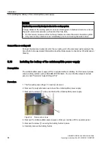


● Attach the cable shield to a shield busbar directly after the line inlet into the cabinet. Insulate
the shielded cable without any interruptions. Route the cable shield up to the device
connection.
①
Shield busbar
②
Shielded cable
③
Mounting clip
Figure 6-1
Shield connection using a clip
NOTICE
Impaired functionality as a result of damaged or incorrectly connected cable shields
Incorrect connection or damaging of the cable shield can impair the function of the system.
● Handle the cable shield carefully.
● Ensure that the cable shield is correctly connected.
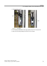
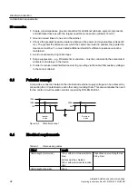
● Bridge shield gaps (at terminals, circuit-breakers, contactors, etc.) with minimum
impedance and through the largest possible surface area.
①
Shield busbars
②
Cables
③
Terminals
Figure 6-2
Bridging shield gaps
Electrical connection
6.2 Electromagnetic compatibility
SINAMICS GM150 6SL3835-2LN44-2AA0
Operating Instructions Rev.201910281250 MUSTER
91
Содержание Sinamics GM150 6SL3835-2LN44-2AA0
Страница 2: ...28 10 2019 12 50 V32 00 ...
Страница 14: ...Table of contents SINAMICS GM150 6SL3835 2LN44 2AA0 14 Operating Instructions Rev 201910281250 MUSTER ...
Страница 216: ...Spare parts SINAMICS GM150 6SL3835 2LN44 2AA0 216 Operating Instructions Rev 201910281250 MUSTER ...
Страница 220: ...Service Support SINAMICS GM150 6SL3835 2LN44 2AA0 220 Operating Instructions Rev 201910281250 MUSTER ...
Страница 232: ...Index SINAMICS GM150 6SL3835 2LN44 2AA0 232 Operating Instructions Rev 201910281250 MUSTER ...
Страница 233: ......
Страница 236: ......
Страница 238: ......


