


Electrical installation
4.9 Signal connections
Converter cabinet units
Operating Instructions, 07/2016, A5E03347396A
101
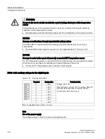
Note
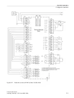
Ensuring the function of digital inputs
An open input is interpreted as "low".
To enable the digital inputs (DI) to function, terminal M2 must be connected.
This is achieved through one of the following measures:
1.
Also route the reference ground of the digital inputs.
2.
A jumper to terminal M. (Note: This removes the electrical isolation for these digital
inputs.)
Note
If the 24 V supply is briefly interrupted, then the digital outputs are deactivated during this
time.
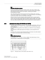
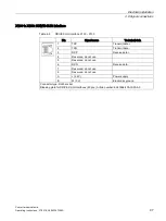
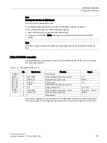
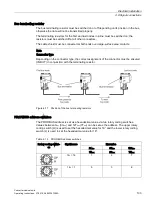
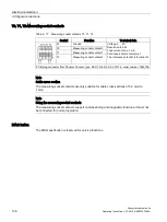
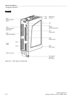
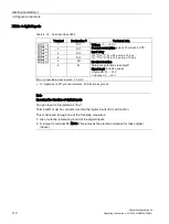
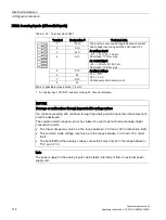
X126: PROFIBUS connection
The PROFIBUS is connected by means of a 9-pin SUB D socket (X126). The connections
are electrically isolated.
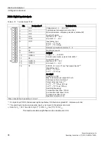
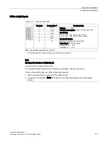
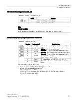
Table 4- 12 PROFIBUS interface X126
Pin
Signal name
Meaning
Range
1
-
Not assigned
2
M24_SERV
Power supply for teleservice, ground
0 V
3
RxD/TxD–P
Receive/transmit data P (B)
RS485
4
CNTR–P
Control signal
TTL
5
DGND
PROFIBUS data reference potential
6
VP
Supply voltage plus
5 V ± 10%
7
P24_SERV
Power supply for teleservice, + (24 V)
24 V (20.4 ... 28.8 V)
8
RxD/TxD–N
Receive/transmit data N (A)
RS485
9
-
Not assigned
A teleservice adapter can be connected to the PROFIBUS interface for remote diagnostics.
The power supply for the teleservice (terminals 2 and 7) can have a load of up to 150 mA.
Содержание SINAMICS G150
Страница 1: ......
Страница 2: ......
Страница 8: ...Foreword Converter cabinet units 8 Operating Instructions 07 2016 A5E03347396A ...
Страница 18: ...Table of contents Converter cabinet units 18 Operating Instructions 07 2016 A5E03347396A ...
Страница 38: ...Device overview 2 5 Type plate Converter cabinet units 38 Operating Instructions 07 2016 A5E03347396A ...
Страница 679: ......
Страница 680: ......


