


Understanding Module Operation
3-6
High Speed Counter Encoder Module User Manual
3.3
Reading Module Status
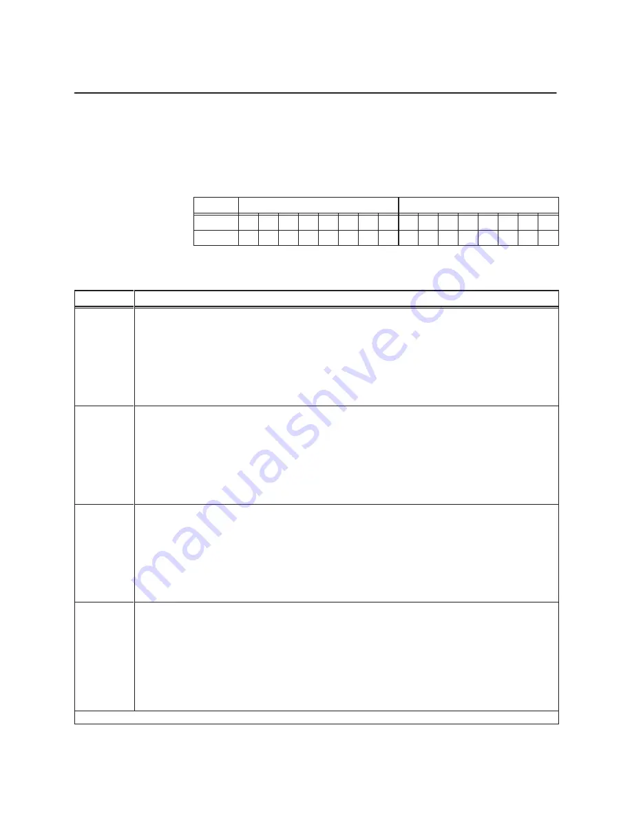
The PLC reads the module status bits in word inputs WX17 and WX18. The
on/off status of the eight outputs, count direction, interrupts, module mode,
error conditions, and other indicators are contained in these words, listed in
Table 3-6. (Status word format is shown in Table 3-5.)
Table 3-5
Module Status Words
Word
MSByte
LSByte
WX17
1
2
3
4
5
6
7
8
9
10
11
12
13
14
15
16
WX18
1
2
3
4
5
6
7
8
9
10
11
12
13
14
15
16
Table 3-6
Bit Definitions for Status Words WX17 and WX18
Word.Bit
Description
WX17.01
WX17.02
WX17.03
WX17.04
WX17.05
WX17.06
WX17.07
WX17.08
Not used (0)
Not used (0)
Ch1, Counters 2 and 3: count up when bit is set, count down when bit is cleared
Ch1, Counter 1: Quadrature direction; count up when bit is set, count down when bit is cleared*
Ch1, Counter 1: Sign; set after counter is reset or when it overflows; cleared when it underflows
Ch1, Counter 1: Compare Toggle; cleared after a counter reset; toggles when count equals preset
Ch1, Counter 1: Carry Toggle; cleared after a counter reset; toggles when counter overflows
Ch1, Counter 1: Borrow Toggle; cleared after a counter reset; toggles when counter underflows
WX17.09
WX17.10
WX17.11
WX17.12
WX17.13
WX17.14
WX17.15
WX17.16
Not used (0)
Not used (0)
Ch2, Counters 5 and 6: count up when bit is set, count down when bit is cleared
Ch2, Counter 4: Quadrature direction; count up when bit is set, count down when bit is cleared*
Ch2, Counter 4: Sign; set after counter is reset or when it overflows; cleared when it underflows
Ch2, Counter 4: Compare Toggle; cleared after a counter reset; toggles when count equals preset
Ch2, Counter 4: Carry Toggle; cleared after a counter reset; toggles when counter overflows
Ch2, Counter 4: Borrow Toggle; cleared after a counter reset; toggles when counter underflows
WX18.01
WX18.02
WX18.03
WX18.04
WX18.05
WX18.06
WX18.07
WX18.08
Module in Run mode (Run flag)
Update Preset values complete
Error Flag
User output power failure detected, or voltage below limits for proper operation
Interrupt function is enabled
Latched Interrupt is active
Outputs are disabled
Counters 1 & 4 count format: double 16-bit signed integer (0) or 32-bit signed integers (1)
WX18.09
WX18.10
WX18.11
WX18.12
WX18.13
WX18.14
WX18.15
WX18.16
WX18.01 = 1, 18.06 = 0
Interrupt Active Mode (WX18.01 = 1 and WX18.06 = 1)
Output 8 On/Off status
Output 8 has changed state, causing interrupt request to the PLC
Output 7 On/Off status
Output 7 has changed state, causing interrupt request to the PLC
Output 6 On/Off status
Output 6 has changed state, causing interrupt request to the PLC
Output 5 On/Off status
Output 5 has changed state, causing interrupt request to the PLC
Output 4 On/Off status
Output 4 has changed state, causing interrupt request to the PLC
Output 3 On/Off status
Output 3 has changed state, causing interrupt request to the PLC
Output 2 On/Off status
Output 2 has changed state, causing interrupt request to the PLC
Output 1 On/Off status
Output 1 has changed state, causing interrupt request to the PLC
*When counter is in non-quadrature mode, this bit is set.
Module Status
Words


