S5-95F
Addressing
6
Addressing
The two subunits of the S5-95F are provided with various types of inputs and outputs. The inputs
and outputs located on the programmable controller itself are called onboard I/Os. The other I/Os
are the failsafe, external I/Os specially developed for the S5-95F and the non-failsafe standard I/Os
from the S5-100U programmable controller with which you can expand your S5-95F.
To access the inputs and outputs, you must assign them specific addresses.
The onboard I/O addresses cannot be changed. The external I/O addresses are slot-dependent.
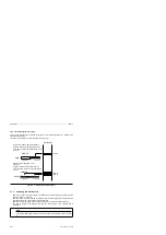
Address Assignment for External I/O Modules
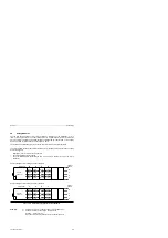
When you mount an external I/O module in a slot on a bus unit, the module is immediately assigned
a slot number and consequently a fixed byte address in the process image I/O tables.
Connect the sensors and actuators either via a connector or to the terminal block of the bus units.
The terminal selected determines the bit address (channel number) of the input or output.
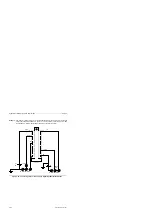
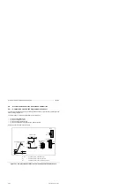
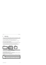
Figure 6-1. Address Assignment
I/O module
=
Process image I/O
tables in the PLC
Slot number
+
channel number
Control
program
Address in a
statement
Address in the
process image output
table
Address in the
process image input
table
Data flow from module - PLC
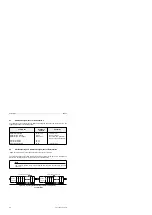
Addressing of Single-Channel External I/Os
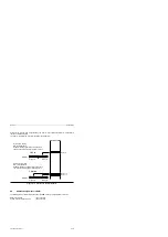
Single-channel I/Os are never failsafe. In the user program, these I/Os must always be referenced
under the address under which they are used in the relevant subunit.
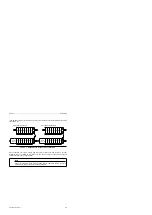
Addressing of Two-Channel, Failsafe External I/Os
Two-channel I/Os can be used only with the failsafe onboard I/Os or with redundant failsafe external
I/O modules.
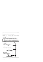
Note
You must always address failsafe external I/Os in the user program at the address where
they are used in subunit A (failsafe external I/Os have always an even-numbered byte
address)!
EWA 4NEB 812 6210-02
6-1


