Communications Capabilities
S5-115U Manual
12.5.1 Data Interchange over the SI 2 Interface
The data to be transferred must be entered in an area of memory designated as the "Send
mailbox". Conversely, the data to be received requires a "Receive mailbox", and an area in
memory must therefore also be designated for this purpose (detailed information is presented in
the next section). The data is stored temporarily in interface SI 2's input or output buffer.
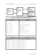
Figure 12-18 illustrates the procedures involved in data interchange.
Figure 12-18. Data Interchange over the SI 2 Interface
CPU RAM
Interface SI 2
Input buffer
(1024 bytes)
Output buffer
(1024 bytes)
Receive mailbox
Send mailbox
Peripheral
device
Initializing a Communications Link
The 3964/3964R line procedure requires certain information which must be made available in
specific system data words.
This includes:
•
The location of the data to be transferred in CPU RAM (the so-called "Send mailbox")
•
The location of the receive data in CPU RAM (the so-called "Receive mailbox")
•
The location of the "Coordination byte, Send" (CBS) and the "Coordination byte, Receive"
(CBR) in CPU RAM. These bytes initiate sending/receiving, and also contain an error code
should a transmission error occur.
•
The location of the parameter list in CPU RAM (this list contains parameters such as the baud
rate, parity and the like).
The line procedure also requires the following information, which again must be made available
in system data words:
•
Mode number (data transmission mode, 3964 or 3964R line procedure)
•
Number of the driver for the 3964/3964R line procedure (referred to from now on as the
communications link).
The Send mailbox, the Receive mailbox, the Send coordination byte (CBS), the Receive coordi-
nation byte (CBR) and the parameter list may be located in either the flag area or in a data block.
You must store the position of the send and receive mailboxes, CBS, CBR, the parameter set and
mode number in the user program in system data words 48 to 55, e.g. with the T RS operation. See
Table 12-14 for the precise assignment. In addition, the computer link must be activated by en-
tering the driver number in SD 46.
12-40
EWA 4NEB 811 6130-02b
Содержание SIMATIC S5-115U
Страница 6: ...EWA 4NEB 811 6130 02b ...
Страница 16: ...EWA 4NEB 811 6130 02b ...
Страница 18: ...EWA 4NEB 811 6130 02b ...
Страница 26: ......
Страница 62: ...EWA 4NEB 811 6130 02b ...
Страница 64: ...EWA 4NEB 811 6130 02b ...
Страница 67: ......
Страница 74: ......
Страница 79: ......
Страница 80: ......
Страница 81: ......
Страница 82: ......
Страница 83: ......
Страница 84: ......
Страница 97: ......
Страница 98: ......
Страница 99: ......
Страница 114: ...EWA 4NEB 811 6130 02b ...
Страница 280: ...EWA 4NEB 811 6130 02b ...
Страница 372: ...EWA 4NEB 811 6130 02b ...
Страница 432: ...EWA 4NEB 811 6130 02b ...
Страница 442: ......
Страница 528: ...EWA 4NEB 811 6130 02b ...
Страница 590: ......
Страница 591: ......
Страница 592: ......
Страница 593: ......
Страница 594: ......
Страница 600: ...EWA 4NEB 811 6130 02b ...
Страница 602: ...EWA 4NEB 811 6130 02b ...
Страница 604: ...EWA 4NEB 811 6130 02b ...
Страница 624: ...EWA 4NEB 811 6130 02b ...
Страница 632: ...EWA 4NEB 811 6130 02b ...
Страница 644: ...EWA 4NEB 811 6130 02b ...
Страница 646: ...EWA 4NEB 811 6130 02b ...
Страница 652: ...EWA 4NEB 811 6130 02b ...
Страница 654: ...EWA 4NEB 811 6130 02b ...
Страница 660: ...EWA 4NEB 811 6130 02b ...
Страница 662: ...EWA 4NEB 811 6130 02b ...
Страница 666: ...EWA 4NEB 811 6130 02b ...
Страница 668: ...EWA 4NEB 811 6130 02b ...
Страница 674: ...EWA 4NEB 811 6130 02b ...

