background image


SIMATIC RF185C, RF186C, RF188C, RF186CI, RF188CI 
Operating Instructions, 04/2020, C79000-G8976-C512-03 

61


  Configuring with the WBM


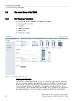
The communication modules are equipped with a Web server that provides Web Based 

Management (WBM) to the Web client for configuring the communication modules. The 

WBM can be called via the Web browser of a PC/laptop. 
The WBM server provides the Web client (PC/laptop) with the parameter data of the 

communication module and accepts parameter changes from the Web client. Note that 

changed parameter values are not automatically transferred to the communication module. 

You must always manually transfer changes to the configuration to the communication 

module. 
In the following, the term "WBM" is used to represent the WBM interface displayed in the 

Web browser. 


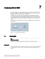
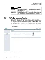
Figure 7-1 

Design and function of the WBM 

7.1


Starting WBM 


Note 
Up-to-date screenshots 
Note that the following screenshots may not reflect the current firmware version. 


Requirement 

The communication module is connected, turned on and ready for operation ("RUN" LED is 

lit or flashing green) and the relevant communication module has been assigned an IP 

address. 
 

Содержание SIMATIC RF185C

Страница 1: ...12 03 Introduction 1 Security recommendations 2 Description 3 Mounting 4 Connection 5 Configuring 6 Configuring with the WBM 7 Programming via SIMATIC controller 8 Programming via XML 9 Programming via OPC UA 10 Programming via Rockwell controller 11 Service and maintenance 12 Technical data 13 Dimension drawings 14 Appendix A Syslog messages B Service Support C ...

Страница 2: ...rsonnel qualified for the specific task in accordance with the relevant documentation in particular its warning notices and safety instructions Qualified personnel are those who based on their training and experience are capable of identifying risks and avoiding potential hazards when working with these products systems Proper use of Siemens products Note the following WARNING Siemens products may...

Страница 3: ...y 30 5 3 Electrical design of the CM 33 5 4 Connecting CM to functional ground 36 5 4 1 Mounting the CM on a conductive base 36 5 4 2 Mounting the CM on a non conductive base 38 5 5 Connecting the communications module 40 5 6 Supply voltage and PROFINET IO loop through 45 5 7 Effect of cable length on the supply voltage 46 6 Configuring 47 6 1 Assign the IP address device name 47 6 1 1 Assigning t...

Страница 4: ...9 Programming via XML 113 10 Programming via OPC UA 115 10 1 Supported methods functions 116 10 2 OPC UA variables 122 10 2 1 Description of the variables 122 10 2 2 ExecuteScan 122 10 2 3 SimaticIdentModelVersion 123 10 2 4 CommonSettings 123 10 2 5 RfidSettings 124 10 2 6 Diagnosis 125 10 2 7 DigitalIOPorts 133 10 3 OPC UA events 135 10 3 1 Description of the events 135 10 3 2 AutoIdPresenceEven...

Страница 5: ...cing a module 177 13 Technical data 179 13 1 Technical specifications RF185C RF186C RF188C 179 13 2 Technical specifications for RF186CI RF188CI 181 14 Dimension drawings 183 A Appendix 185 A 1 System planning 185 A 2 Connecting cables 186 A 2 1 Standard cables 186 A 2 2 Custom assembled connecting cables 186 A 3 Operation of optical handheld readers access control readers or serial devices 188 A ...

Страница 6: ...Table of contents SIMATIC RF185C RF186C RF188C RF186CI RF188CI 6 Operating Instructions 04 2020 C79000 G8976 C512 03 ...

Страница 7: ... MOBY RF MANAGER SIMATIC Sensors Orientation in the documentation In addition to these operating instructions you require the operating instructions for the S7 300 S7 400 S7 1200 or S7 1500 controller used When using an S7 controller you can find information on programming the module and a complete error description in the description of the Ident profile and Ident blocks function blocks the RFID ...

Страница 8: ...rface module ASM Recycling and disposal The products are low in harmful substances can be recycled and meet the requirements of the Directive 2012 19 EU for disposal of waste electrical and electronic equipment WEEE Do not dispose of the products at public disposal sites For environmentally compliant recycling and disposal of your electronic waste please contact a company certified for the disposa...

Страница 9: ...trict physical access to the device to qualified personnel Lock unused physical ports e g Ethernet ports on the device Unused ports can be used to access the system without authorization Software security functions Keep the software up to date Keep yourself informed regularly about safety updates for the product You can find information about this at Link https www siemens com industrialsecurity A...

Страница 10: ...with the security keys and certificates that you need to set up SSL We urgently recommend creating your own SSL certificates and making them available Preset certificates and keys are present in the device The preset and automatically created SSL certificates are self signed We recommend using certificates signed either by a reliable external certification authority or an internal certification au...

Страница 11: ...on The firmware itself is signed and encrypted This ensures that only authentic firmware can be downloaded to the device Secure non secure protocols Check whether it is necessary to use SNMPv1 SNMPv1 is classified as non secure Make use of the possibility to prevent write access The product offers corresponding settings for this If SNMP is activated change the community names If unrestricted acces...

Страница 12: ...ntication Encryption DHCP UDP 68 Open No No PROFINET UDP 34964 UDP 49152 65535 Open No No HTTP TCP 80 Open No No HTTPS TCP 443 Open Yes Yes NTP UDP 123 Closed No No SNMP UDP 161 Closed No No OPC UA TCP 4840 Open Yes when configured Yes when configured EtherNet IP TCP 44818 UDP 44818 UDP 2222 Open No No XML TCP 10001 Open No No XML TCP 10002 Closed No No XML TCP 10003 Closed No No XML TCP 10004 Clo...

Страница 13: ...mponents should only be connected to an enterprise network or the internet if and to the extent such a connection is necessary and only when appropriate security measures e g firewalls and or network segmentation are in place For additional information on industrial security measures that may be implemented please visit Link https www siemens com industrialsecurity Siemens products and solutions u...

Страница 14: ...Security recommendations SIMATIC RF185C RF186C RF188C RF186CI RF188CI 14 Operating Instructions 04 2020 C79000 G8976 C512 03 ...

Страница 15: ...88C as well as RF186CI and RF188CI Due to the high degree of protection mounting without a protective enclosure is possible directly near the RFID read points The small mounting surface of the communication module facilitates installation in confined spaces Two connections each for Ethernet and power supply allow configuration in a line structure in addition to a star structure The L coded M12 con...

Страница 16: ...nterface 2x M12 switch integrated Transmission speed 100 Mbps Degree of protection IP67 Application protocols PROFINET IO EtherNet IP OPC UA XML Configuration diagnostic options STEP 7 TIA Portal GSDML WBM Web browser Function blocks Ident profile FB 45 faceplate for PCS 7 Supported SIMATIC controllers S7 300 S7 400 S7 1200 S7 1500 Supported third party controllers Source code of the Ident profile...

Страница 17: ...ss data are supported input and output data Note that the SIMATIC RF200 IO Link Ident readers cannot be operated via SIMATIC RF186CI RF188CI 3 3 User specific procedure As described above the communication modules are designed for different environments and requirements If you operate the communication modules in an automation environment they are configured and programmed from the perspective of ...

Страница 18: ...ess device name You can find information on this in the section Assigning the IP address device name with SINEC PNI Page 50 3 Configure the communication module You can find information on this in the section Configuring with the WBM Page 61 4 Program the reader commands You can find information on this in the section Programming via XML Page 113 Procedure as Rockwell user 1 Connect the hardware Y...

Страница 19: ...ecific contain these symbols Sections without these symbols are general and relevant for all areas of application 3 4 Design The following figure shows the basic design of the RF18xC RF18xCI Status LEDs 2x interfaces for PROFINET IO M12 4 pin D coded Reader interfaces M12 8 pin A coded Mounting holes and functional ground Reader LEDs I O interface 1 M12 5 pin A coded PROFINET Ethernet LEDs IO LEDs...

Страница 20: ... modules are integrated into the TIA Portal as of STEP 7 Basic Professional V16 the RF18xCI communication modules are integrated into the TIA Portal Integration into older STEP 7 versions and third party systems is performed via a GSDML file The communication module can then be configured via the TIA Portal or another engineering system The GSDML file is stored on the communication module and can ...

Страница 21: ...nlight precipitation and wind 4 1 Installation dimensions and position The RF18xC RF18xCI communication modules have the following installation dimensions W H D 60 165 45 mm You can mount the communication modules in any mounting position Minimum clearances When installing the communication modules keep a minimum distance of 1 cm from an adjacent device or another device Mounting rules Note Mounti...

Страница 22: ... module already establishes a reliable grounding connection This eliminates the need for a separate ground conductor If you use the fixing screw as grounding connection the thread of the fixing screw or the contact facing of the fastening nut on the base must be unpainted This ensures a low resistance connection Requirements The following table shows and explains the types of screws you need to mo...

Страница 23: ...ons 04 2020 C79000 G8976 C512 03 23 Procedure Fasten the communication module with the screws on a solid level surface The device must be screwed 1 2 Nm onto the panel at both fastening points front top and bottom Elongated hole 4 5 mm width 5 0 mm height Figure 4 1 Installing RF18xC RF18xCI communication module ...

Страница 24: ...e the following information and restrictions in this regard Restrictions of the maximum specified ambient temperature Table 4 2 Restrictions of the maximum specified ambient temperature with regard to the altitude Altitude Derating factor Max permissible ambient tem perature 1000 2000 m 1 0 55 2000 3000 m 0 9 49 C 3000 4000 m 0 8 44 C 4000 5000 m 0 7 38 C The standard IEC 61131 2 2017 forms the ba...

Страница 25: ...r rate of electronic components so called Soft Error Rate In rare cases this may result in the module entering the safe state this is especially true for safety modules However the functional safety of the module remains completely unaffected Currently valid markings and approvals Note Information on the nameplate You will find the currently valid markings and approvals on the nameplate of the com...

Страница 26: ...Mounting 4 3 Use at altitudes over 2 000 m SIMATIC RF185C RF186C RF188C RF186CI RF188CI 26 Operating Instructions 04 2020 C79000 G8976 C512 03 ...

Страница 27: ...he SIMATIC PROFINET system description https support industry siemens com cs ww en view 19292127 CAUTION Power supply for devices with PROFINET interfaces Modules with PROFINET interfaces may only be operated in LANs Local Area Networks in which all connected devices are equipped with SELV PELV power supplies or have equivalent protection A data transfer terminal modem for example is required to a...

Страница 28: ...he communication module using a preassembled cable The connection cable is available in lengths of 2 5 10 20 and 50 m as standard If necessary these can be extended Figure 5 1 Overview of connections 5 1 Network topology The communication network can be designed as line series star or ring topology Also note the information in the section Supply voltage and PROFINET IO loop through Page 45 Figure ...

Страница 29: ...ed Figure 5 3 Configuration graphic of a star topology Figure 5 4 Configuration graphic of a ring topology Media redundancy Media redundancy is a function that ensures network and system availability Redundant transmission links in the MRP topology ensure that an alternative communication path is made available if a transmission link fails To make this possible you need to configure the communicat...

Страница 30: ...overload protection according to IEC 60364 corresponds to DIN VDE 0100 and IEC 60204 corresponds to DIN VDE 0113 Load voltage supplies and load circuits Grounded power supply For grounded power supplies the neutral conductor of the supply system is grounded A short circuit to ground of a live conductor or of a grounded part of the system trips the protective devices Supply voltages Two supply volt...

Страница 31: ... up RF18xC RF18xCI with ungrounded reference potential When the communication module is set up with ungrounded reference potential any interference currents occurring are conducted to functional ground via an internal RC network no external connection between 1M and FE RF18xC RF18xCI in total configuration The following figure shows the communication module in its overall electrical design Main sw...

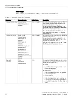
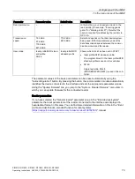
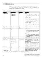
Страница 32: ...he previous figure and compares the IEC regulations Table 5 1 Components of the electrical design Screen num ber Components IEC 60364 IEC 60204 Disconnecting device for controller sensors and actuators Main switch Disconnector Short circuit and overload protection Single pole protection of circuits Protect all power supply lines with a 24 V DC 16 A circuit breaker Single pole protection must be us...

Страница 33: ...ation In the electrical design of the communication module electrical isolation is provided between Load voltage 2L and all other circuit components Communication interfaces PROFINET of the communication module and all other circuit components The following figure shows the potential relationships of the communication modules Figure 5 6 Potential relationships of the communication modules ...

Страница 34: ...equired in order to supply all communication modules of an assembly with the required voltage Another voltage supply of 1L and 2L may be needed to form different potential groups or because the voltage is insufficient for all communication modules due to the voltage drop Create a power budget for the selection of the supply point of the voltage Note Switching 1L and 2L on and off Note that the pow...

Страница 35: ...188C RF186CI RF188CI Operating Instructions 04 2020 C79000 G8976 C512 03 35 The following figure shows a configuration with another voltage supply for the communication modules The different potential groups are highlighted in gray Figure 5 7 Wiring of the power supply ...

Страница 36: ...gainst external electrical influences Below is a description of what you must pay attention to in terms of protection against electrical impacts and or faults In all plants or systems in which the communication module is installed you must ensure that the plant or the system for dissipating electromagnetic interference is connected to functional ground For supply signal and bus lines you must ensu...

Страница 37: ...he module together with the M4 fastening screws with a torque of 1 2 Nm NOTICE Grounding with a conductive mounting base If you fasten the communications module to a conductive grounded base the lower fastening screw provides a conductive connection to the ground potential Ensure there is a low impedance connection between the communications module and the conductive base and between the conductiv...

Страница 38: ...uctive base for mounting the module Required tools You need the following tools to connect to the functional ground Screwdriver Stripping tool Crimp tool Accessories required To connect to functional ground with a non conductive mounting base you can need the following accessories Fastening screw M4 and washer Cable lug suitable for M4 screws Ground conductor cable copper braid with a minimum cros...

Страница 39: ...or 1 Drill 2 mounting holes with a distance of 155 6 mm 2 Insulate the ground conductor 3 Attach the cable lug to the ground conductor 4 Screw the module and the cable lug together with the M4 fastening screws with a torque of 1 2 Nm NOTICE Grounding with non conductive mounting base Ensure a low impedance connection between the communications module and functional ground Figure 5 9 Mounting the C...

Страница 40: ... pin A coded Mounting holes and functional ground Reader LEDs I O interface 1 X10 M12 5 pin A coded PROFINET Ethernet LEDs IO LEDs 1 2x interfaces for the power supply X80 X81 M12 4 pin L coded Figure 5 10 Design of the communication module 1 The I O interface and the associated LEDs are only a feature of the CI devices You can loop the supply voltages and PROFINET IO via the M12 round sockets The...

Страница 41: ...lf ensure that the conductor cross section matches the system setup or the corresponding protection 1 5 mm2 When using cables that are not preassembled you need the tool for the specific cable connector for example an insulation stripper screwdriver or Allen wrench Accessories required You need the following accessories for the reader connection M12 plug 8 pin A coded and 6 wire cable 6 x 24 AWG f...

Страница 42: ...in assignment for the interfaces connectors Table 5 2 Pin assignment PROFINET IO M12 socket 4 pin D coded Pin Assignment View of M12 socket 4 pin 1 Data line TxP 2 Data line RxP 3 Data line TxN 4 Data line RxN Table 5 3 Pin assignment power supply M12 socket 4 pin L coded Pin Assignment View of M12 socket 4 pin 1 L1 24 V brown 2 N2 0 V load supply white Relevant for RF18xCI devices 3 N1 0 V blue 4...

Страница 43: ... TxD 5 V 6 TxD 7 TxD 8 Functional ground shielding Functional ground shielding I O interface RF18xCI Note that a single input a single output or an IO Link module e g IO Link module K20 can be connected to the I O interface Table 5 5 Pin assignment I O interface M12 socket 5 pin A coded Pin Assignment View of M12 socket 5 pin 1 1L 24 V IO Link 2 2L 24 V for IO Link module Class B 3 1N GND IO Link ...

Страница 44: ...nector by tightening the knurled locking ring To guarantee the degree of protection you must fasten all connectors with 1 0 Nm NOTICE Ensuring the degree of protection You need to close all unused sockets with M12 sealing caps to ensure IP65 or IP67 degree of protection You can find the order data of the sealing caps in the section Ordering data Page 196 Connector for the reader connection M12 8 p...

Страница 45: ...tion module is 16 A at 1L and 2L for a maximum ambient temperature of 40 C At ambient temperatures of 40 C to 55 C the maximum supply current is 12 A These values must not be exceeded Take note of the derating factor when operating at elevations above 2000 m Page 24 Adhere to the current carrying capacity of the connected cables which depends on the conductor material the conductor cross section a...

Страница 46: ...e example of a copper cable with 1 5 mm2 A simple copper line is used as an example Depending on the design the power supply line and the ground line must be taken into account Figure 5 13 Voltage drop with copper cables with a cross section of 1 5 mm2 To estimate the voltage drop in your communication module you must add the voltage drops of the cables Example With 16 A the voltage drop via the t...

Страница 47: ...e communication module as an S7 user in an automation environment The unique assignment is made via the device name using the TIA Portal from STEP 7 Basic Professional V15 Operate the communication module as XML or OPC UA user in an IT environment The unique assignment is based on DHCP or the IP address using SINEC PNI Operate the communication module as a Rockwell user EtherNet IP in an automatio...

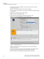
Страница 48: ... into the project 6 Assign the communications module to the controller 7 Right click on the communications module 8 In the shortcut menu select the menu command Assign device name Reaction The Assign PROFINET device name window opens Figure 6 1 Assign device name 9 Select the connection type in the Online access area in the Type of the PG PC interface drop down list 10 In the PG PC interface drop ...

Страница 49: ...f several IO devices are connected to the controller it is possible to make the LEDs of the device flash In this case compare the MAC address of the device with the MAC address displayed and then select the desired IO device With the help of the device flash test you can quickly and easily identify the desired IO device Proceed as follows to identify the relevant IO device using the flashing test ...

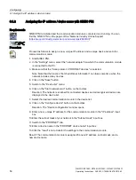
Страница 50: ...ected Note Note that the function Fetch additional information can take some time when the network includes many devices 4 Click on the Save button 5 Switch to the Device list menu 6 Click on the Start network scan button on the toolbar Reaction The network is scanned for connected devices and all recognized devices are displayed in the device list 7 Select the desired communication module in the ...

Страница 51: ... assign the communication module an IP address via DHCP a DHCP server must be configured in the same subnet Rockwell Automation makes a BOOTP DHCP server for Windows available to assign IP address data to the MAC address of the reader Requirement Studio 5000 Logix Designer and a current version of the BOOTP DHCP server are installed the communication module is linked in and the communication modul...

Страница 52: ...ic Professional V15 1 the RF18xC communication modules are integrated into the TIA Portal as of STEP 7 Basic Professional V16 the RF18xCI communication modules are integrated into the TIA Portal and can be linked to SIMATIC automation systems Integration into older STEP 7 versions is performed via a GSDML file The connection is made via PROFINET the configuration via the TIA Portal and operation o...

Страница 53: ... the communication module from the hardware catalog into the project 4 Optional Switch to the device view and delete an existing module e g Reader_1 if necessary and drag a suitable module from the hardware catalog into the corresponding module column 5 Connect the communication module with the controller 6 Configure the communication module e g device name address range 7 Assign parameters to the...

Страница 54: ...ameter group Table 6 2 Parameters of the Configuration management parameter group Parameter Description User name 1 User name of a user created on the communication module Note that the user must have the required rights Password 1 Enter the password for the user Load configuration to device Load configuration data from the STEP 7 project into the communication module Save configuration in project...

Страница 55: ...cted to interface X21 you need to assign an Empty module to this interface Table 6 4 Parameters of the parameter group Module parameters General parameters of the submodules connect ed readers Parameter Parameter value Default value Description User mode Ident profile RFID stand ard profile FB 45 Ident profile RFID standard profile With this parameter you select the block Ident profile RFID standa...

Страница 56: ... be reported None No alarms are generated Hard errors Critical hardware errors faults are reported by the S7 diagnostics Hard soft errors Critical hardware faults and errors occurring when processing commands are reported by the S7 diagnostics IO mode 1 Input Output IO Link Input You use this parameter to specify the mode of the I O interface of the communication module Input Single digital input ...

Страница 57: ...or 1 the parity bit is added to the sum of all bits data bits and parity bits to form a defined status This in creases data reliability None Data is sent without a parity bit Odd The parity bit is set so that the sum of the data bits including the parity bit is odd when the signal state is 1 Even The parity bit is set so that the sum of the data bits including the parity bit is even when the signa...

Страница 58: ...1 2 1 Selection of the number of end delimiters A maximum of 2 end delimiters can be config ured When data is received the end of the frame is recognized when the selected end delimiter combination is received 1st end delimiter 0 255 3 Entry of the first end delimiter of a maximum of two end delimiters for the end criteria On re ceipt of the end delimiter s The selected end delimiter or the select...

Страница 59: ... via XML This section is intended only for XML users Configuration of the communication module is not necessary for pure XML work You can continue directly with configuration via WBM and with programming via XML You can find detailed information on the XML diagnostic functions in the XML programming for SIMATIC Ident https support industry siemens com cs ww en ps 14971 man manual 6 4 Configuration...

Страница 60: ...ile and the add on instructions in the Ident profile and Ident blocks standard function for Ident systems https support industry siemens com cs ww en view 109762333 function manual Note Serial number in Studio 5000 Logix Designer Note that the serial number specified in the Studio 5000 Logix Designer does not match the communication module serial number The serial number specified in the Logix Des...

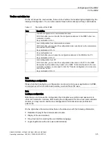
Страница 61: ...anges from the Web client Note that changed parameter values are not automatically transferred to the communication module You must always manually transfer changes to the configuration to the communication module In the following the term WBM is used to represent the WBM interface displayed in the Web browser Figure 7 1 Design and function of the WBM 7 1 Starting WBM Note Up to date screenshots N...

Страница 62: ...t at the time of publication of this manual Microsoft Internet Explorer Microsoft Edge Mozilla Firefox and Google Chrome The user interface of the WBM is designed for a screen resolution of 1366 x 768 pixels Procedure Proceed as follows to start the WBM 1 Start your Web browser 2 Enter the IP address of the communication module in the address field of your browser 3 Confirm your entry by pressing ...

Страница 63: ...nable user management After starting the WBM the first time no user management is enabled To make sure that no unauthorized persons can access the communication module settings we recommend that you enable the user management and create new user profiles after the first login Note that user administration can only be enabled by an administrator During your first login as administrator User admin p...

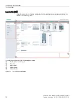
Страница 64: ...9000 G8976 C512 03 Layout of the WBM Once the connection to the communication module has been successfully established the WBM start window appears The WBM start window is divided into the following areas Toolbar status bar and log on Menu tree Main window Message area Information bar Figure 7 3 Start window of the WBM ...

Страница 65: ...onfiguration from PC With this button you can load the configuration data stored on the PC in the WBM Remember that this data is only loaded in the WBM To transfer the data to the com munication module you also need to click the Transfer configuration to communica tion module button Key combination Ctrl O Note Transferring a configuration Please note that transferring a configuration can disrupt r...

Страница 66: ...gnostics Interface specific diagnostics function Log Overview of log entries Service log Information for service cases Syslog log Overview of Syslog messages Edit transponder Reading out and writing transponder data User management Enabling disabling user management Creating and deleting user profiles Changing passwords System System settings Performing a firmware update for the communication modu...

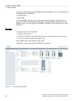
Страница 67: ...y ten increments Home End The value is set to the minimum or maximum value Message area The message area displays all WBM related error messages and warnings e g transfer errors Information bar The information bar displays deviations between the settings in the user interface of the WBM and the configuration stored on the connected communication module Minor deviations are designated by a yellow s...

Страница 68: ... Figure 7 4 The Start page menu item Device specific information The first area contains device specific information The Device type MLFB Hardware and Serial number boxes are specified in the factory The content of the Firmware and Firmware version boxes depends on the firmware stored on the communication module Using the Update firmware link you jump to the System menu item in which you can updat...

Страница 69: ...ess Device clock With the Synchronize with PC button you can synchronize the device clock with the time in your operating system Note The device time always corresponds to UTC time Note that the time of the device clock corresponds to UTC time and cannot be adjusted to time zones Clicking the button transfers the local time stored in your operating system to the communication module Because the ti...

Страница 70: ... check boxes to decide which events are entered in the log The log is structured as a circular buffer Bear in mind that with a high degree of detail of the data the circular buffer fills up more quickly which can have a negative effect on the performance of the device Table 7 4 Description of the parameters of the log Parameter Description General COMMON Messages relating to general events e g rea...

Страница 71: ...n be switched off if the status commands are used as cable monitoring In this way the logbook is kept free for user data 7 3 3 The Settings Reader Interface menu item With the Settings Reader interface menu item up to four readers can be defined depending on the communication module type If the communication module is connected to an S7 controller the configurations are made via the controller In ...

Страница 72: ...rNet IP Ident devices system Empty module General reader RF200 general RF290R RF300 general RF380R RF300 Gen 2 general RF380R Gen 2 MV400 MV500 General reader Selection of the device system connected to the communication module Depending on the selection made different parameters are shown or hidden in the follow ing Reader parameters section If no device is connected to the interface select the E...

Страница 73: ...ID standard profile The program block for the Ident profile RFID standard profile is used on the controller FB 45 Single tag mode FB 45 PROFIBUS PROFINET is used in the con troller The parameter values of the basic parameters can be preset automatically using the Autoconfiguration button By pressing the button the communication module automatically identifies the device connected to the interface ...

Страница 74: ...for the output power of the reader Reset error LED On Off Off On The flashing of the error LED on the reader is reset by each reset and by a new OPC command Off The error LED always indicates the last er ror The display can only be reset by turning off the reader Max number of tran sponders 1 40 1 Number of transponders expected in the anten na field Reader mode Normal operation P2P master P2P mas...

Страница 75: ... type parameter Selection of the transponders used The selection depends on the value specified in the parameter Ident device system The following transponder types can be selected Ident device system Value transponder types RF290R ISO 15693 MDS D3xx Infineon RF300 general RF380R RF300 ISO 15693 General MDS D3xx Infineon MDS D4xx Fujitsu 4 KB MDS D1xx NXP MDS D2xx TI MDS D261 STM RF300 Gen 2 gener...

Страница 76: ...and parity bits to form a defined status This in creases data reliability None Data is sent without a parity bit Odd The parity bit is set so that the sum of the data bits including the parity bit is odd when the signal state is 1 Even The parity bit is set so that the sum of the data bits including the parity bit is even when the signal state is 1 Fixed value 1 The parity bit is set permanently t...

Страница 77: ...ers 1 2 1 Selection of the number of end delimiters A maximum of 2 end delimiters can be config ured When data is received the end of the frame is recognized when the selected end delimiter combination is received 1st end delimiter 0 255 3 Entry of the first end delimiter of a maximum of two end delimiters for the end criteria On re ceipt of the end delimiter s The selected end delimiter or the se...

Страница 78: ...utputs menu item The menu item Settings Digital outputs is only displayed for the RF186CI and RF188CI communication modules In the Settings Digital outputs menu item you can set the properties of the digital outputs and assign functions to the interface The menu item is divided into the following areas Basic settings Digital outputs Figure 7 7 The Settings Digital outputs menu item ...

Страница 79: ...y Status that the output adopts following device startup Reset time If the reset time is set to a value 0 the output automatically returns to the inactivity status when the reset time has elapsed A value of 0 means that the status of the output is not influenced by this automatic function Value range 0 65535 ms Increment 1 ms Select the check box Ignore PLC to ensure that changes of the output bit...

Страница 80: ...s the output is set to the state specified here Note Reaction time of the digital outputs Note that the reaction time of the digital outputs and inputs depends on the CM load and is 50 100 ms on average Note the following properties of the digital outputs The outputs are only changed once when the event occurs The outputs remain set unchanged even when the event is no longer pending Pending events...

Страница 81: ...ng areas Network ports SNMP NTP Syslog messages Figure 7 8 The Settings Communication menu item Network interfaces tab Network ports In the Network ports area you can enable disable the network ports of the communication module Click on the check box of the required network port to enable or disable it Note Disabling the network ports Make sure that you do not disable the port via which you are cu...

Страница 82: ...for example SNMP In the SNMP area you can enable disable the network protocol SNMP is a protocol for monitoring network components This setting is activated at the factory If you do not use the protocol we recommend that you disable the setting for security reasons Table 7 10 Description of the SNMP properties Property Description Community string reading Input box for specifying the user name for...

Страница 83: ...server Check box to ensure that the communication module also accepts the time from unsynchronized NTP servers Syslog messages In the Syslog messages area you can activate the Syslog messages When the Syslog function is activated the module generates Syslog messages at the preset UDP port according to RFC 5426 Syslog messages log information during access to the module as well as configuration cha...

Страница 84: ...tab Basic settings Select the check box Disable S7 PNIO if you want to ensure that no access to the communication module takes place via the controller STEP 7 With this setting the Ethernet interface is closed for communication with the controller Select the check box Disable EtherNet IP if you want to ensure that no access to the communication module takes place via EtherNet IP With this setting ...

Страница 85: ...Reliable transfer If the check box is selected each frame XML report received from the user application of the communication module is confirmed with a response frame If no response frame is received by the communication module within 10 sec onds it sends the report to the application again Reports that are not trans ferred are buffered on the communication module With this function you can make s...

Страница 86: ...button to enable communication via one XML channel This function automatically presets the interface parameters in the XML channel area With this function communication for both interfaces is performed via one XML channel XML channel In the XML channel area you can define which events are transmitted via the selected XML channel Table 7 14 Description of the parameters Parameter Description Presen...

Страница 87: ... RF188C RF186CI RF188CI Operating Instructions 04 2020 C79000 G8976 C512 03 87 The OPC UA tab The OPC UA tab is divided into the following areas Basic settings Diagnostic settings Security settings OPC UA certificates Figure 7 11 The Settings Communication menu item OPC UA tab ...

Страница 88: ...ication at which the process data is published for logged on OPC UA clients Lower values set by an OPC UA client are not taken into account Range of values 10 65535 ms Default setting 50 ms Diagnostic settings In the Diagnostic settings area you can define which diagnostic information can be called up via specific channels Table 7 16 Description of the parameters Parameter Description Parallel In ...

Страница 89: ...odule uses signing and if configured 256 bit encryption using the hash algorithm SHA 256 It is recommended that you use the highest security level Basic 256 SHA 256 1 The security levels Basic 128 and Basic 256 should only be used if no other security profile can be used due to compatibility reasons Security method Specifying the security method of the server Sign or sign and encrypt Depending on ...

Страница 90: ... partner is not identical to the IP address in its certificate Note The OPC UA server does not check the IP address of its communi cation partner client If no blacklist is stored on the communication module for the CA of the partner certificate Regardless of these exceptions to establish a connection at least the follow ing requirements must be met If the partner certificate is not trustworthy the...

Страница 91: ...eir cer tificates for network participants This means the CA certificates are root certificates for the client certificates Client certificates for which a valid CA certificate exists are automatically accepted during connection setup Issuer certificates Root certificates from certification authorities Unlike CA certificates client certificates derived from issuer certificates must still be accept...

Страница 92: ...he certificate key file are stored in a single file This file is usually protected by a password Enter the password in the text box at the bottom Note that this format can only be used for server certificates cer crt der pem Binary or text coded file format in which the certificate file and the certifi cate key file are stored in separate files Note that the server certificates necessarily require...

Страница 93: ...vel Basic 256 SHA 256 and disable anonymous access 7 3 6 The menu command Diagnostics Hardware diagnostics In Diagnostics Hardware diagnostics you can display the status parameters of the selected reader and of the transponder currently in the antenna field The menu item Diagnostics Hardware diagnostics is divided into the following sections Basic settings Monitoring status Status Error counter Fi...

Страница 94: ...ers of the Reader status area Displayed parameters Description Hardware type Hardware type of the reader Hardware version Hardware version of the reader Bootloader version Bootloader version of the reader Firmware version Firmware version of the reader Driver type Driver type of the serial interface of the reader Driver version Driver version of the serial interface of the reader Interface Used se...

Страница 95: ...e check profile Table 7 20 Displayed parameters of the Transponder status area Displayed parameters Description UID Unique identifier of the transponder Transponder type Transponder type vendor identification Version Version of the transponder chip Lock status of the OTP area Disabled blocks of the OTP area on the chip Size of the user memory Memory size of the user memory in bytes Size of a memor...

Страница 96: ...ns on the air interface that caused com munication to be disturbed SFZ Signature error counter Counter for failed signature encryptions of written blocks of data Only rele vant for the transponder type RF300 CRCFZ CRC error counter Counter for failed CRC checks ASMFZ Error counter for problems on the interface to the host CM PC Counter for errors on the serial interface Signal strength AMLI AM pow...

Страница 97: ...in the Log settings area This menu item documents the actions performed by the communication module The entries contain the following properties Table 7 22 Displayed properties of the log messages Property Description Date time Time stamp when the entry was made by the communication module Note that the time stamp is generated by the device clock UTC time This time is compared with the time zone s...

Страница 98: ...nication module and the list is updated The log entries displayed include the most current data 200 KB Total history The complete stored log of the communication module is read in The log entries displayed include all saved data 10 MB Save The log read by the communication module is saved as a csv file on the PC Reset The log is deleted in the communication module With a large number of log entrie...

Страница 99: ...rocesses of the communication module and is required for service support by SIEMENS specialists Only make settings on this page if you are instructed to do so by SIEMENS personnel The log entries are also evaluated by SIEMENS personnel The Diagnostics Service Log menu item is divided into the following areas Log settings for service Service log Figure 7 14 The Diagnostics Service Log menu item Log...

Страница 100: ...rea The entries contain the following properties Table 7 24 Displayed properties of the log messages Property Description Date time Time stamp when the entry was made by the communication module Note that the time stamp is generated by the device clock UTC time This time is compared with the time zone set on the PC and displayed accordingly Type Type of message Which message types are signaled dep...

Страница 101: ... the Syslog function is enabled This page can only be called by users with administrator rights Figure 7 15 The Diagnostics Syslog logbook menu item All Syslog messages are displayed in the Syslog logbook menu item This menu item documents all safety related accesses to the communication module and actions performed You can find detailed information on the Syslog messages their structure and conte...

Страница 102: ...C512 03 7 3 10 The Edit transponder menu item You can read out and write transponder data with the Edit transponder menu item This page is divided into 2 areas Basic settings Read write Figure 7 16 The Edit transponder menu item Basic settings This area enables you to select the reader or reader interface with which transponders are to be processed ...

Страница 103: ...t the data both in the HEX format or in the ASCII format You can choose between the two input modes Overwrite and Insert Initialize data Show hide the view for initializing the data Using the initialization function you can preset the data fields Next to the list of tag fields the data of the selected memory area is displayed in HEX view With the Read button the data is read from the transponder T...

Страница 104: ...First login to WBM via HTTPS Note that user administration can only be enabled by an administrator During the first login as administrator you must change the password for security reasons The communication modules are delivered with the following user profile pre installed at the factory User name admin Password admin Using the admin user profile you can create new user profiles and delete existi...

Страница 105: ...t box 2 Enter your password in the Password input box 3 Click the Log in button Result You are logged onto the WBM and can now set communication module parameters The User management menu item In the User management menu item you can create delete and edit user profiles and change passwords This page is divided into the following areas User profiles User properties Password Roles User management o...

Страница 106: ...n be changed by the users themselves or an administrator The strength of your password is indicated by color and text If you lose your administrator password you must reset the communication module to the factory settings as described in the section Restoring the factory settings manually Page 173 Roles In the Roles area you can assign roles to the user profile Click the relevant check box to assi...

Страница 107: ...e Run device status Log Restricted The log cannot be reset Syslog log The page is not displayed Edit transponder No operator control is possible in the Run device status User management Restricted Only the user s own password can be changed System No operator control is possible in the Run device status In addition changes cannot be transferred to the communication module using the Transfer config...

Страница 108: ...ry settings change the IP address of the communication module load certificates on the communication module and transfer control files to the PC This page is divided into the following areas Firmware update Reset IP address HTTPS certificate Device description files Figure 7 19 The menu item System System settings Firmware update In the Firmware update area you can update the firmware of the commu...

Страница 109: ...ificate key files to the communication module Remember that you first need to import the data into the communication module before you can activate it Using the certificates you can integrate the communication module in your specific security infrastructure Certificates are used to check the identity of a person or a device to authenticate a service or to encrypt files You can create your own cert...

Страница 110: ...hich a firmware update is to be performed Depending on the connected reader you can select the desired reading point Firmware update In the Firmware update area you can update the firmware of the selected reader For a detailed description of firmware updates refer to the section Firmware update Page 166 7 3 14 The Help menu item Service and Support The Help Service and Support menu item includes i...

Страница 111: ...unication modules have configurable digital inputs outputs that you can configure using the WBM You will find more information on this in the section The Settings Digital outputs menu item Page 78 You can operate the interface as a single input DI 0 or a single output DO 0 and PI 0 as needed or you can connect an IO Link module IO Link modules with up to 8 inputs and or 8 outputs are supported The...

Страница 112: ...Programming via SIMATIC controller 8 1 Digital inputs outputs SIMATIC RF185C RF186C RF188C RF186CI RF188CI 112 Operating Instructions 04 2020 C79000 G8976 C512 03 ...

Страница 113: ...ing via XML 9 This section is intended only for XML users You can program the communication modules via the XML interface using XML commands You can find detailed information on the XML diagnostic functions in the XML programming for SIMATIC Ident https support industry siemens com cs ww en ps 14971 man manual ...

Страница 114: ...Programming via XML SIMATIC RF185C RF186C RF188C RF186CI RF188CI 114 Operating Instructions 04 2020 C79000 G8976 C512 03 ...

Страница 115: ... OPC UA you can also integrate the communication modules into cloud systems or communicate with them Knowledge of fundamental OPC mechanisms as well as programming know how is indispensable for understanding the following section and implementing your own OPC UA client for use with the communication modules The OPC UA standard specifications will help you here The standard OPC Unified Architecture...

Страница 116: ... sensible manner e g antenna power An XML device description file for connection of the communication module via OPC UA is stored on the communication module and can be downloaded via the WBM System Device description file 10 1 Supported methods functions Parallel to regular operation via PC or SIMATIC controller you can read out the results of the SIMATIC commands and diagnostic information via t...

Страница 117: ...This means that each communication module supports as many read points as the number of devices that can be connected On a communication module an OPC UA client can be connected as a main application or as a second application connected in parallel to a PROFINET PROFIBUS EtherNet IP or XML main application For an OPC UA client to also be able to connect in case of a PROFINET PROFIBUS EtherNet IP o...

Страница 118: ...ods functions The integrated OPC UA servers of the communication modules support the following RFID specific methods functions according to the OPC Unified Architecture for AutoID for each read point Table 10 2 RFID specific methods functions OPC UA methods Scan Synchronous execution of inventories The detected transponders are directly returned ScanStart ScanStop Trigger the read points to start ...

Страница 119: ...re version of the communication module LastScanData Most recently scanned transponder of the read point Scan ScanStart Manufacturer Manufacturer always Siemens AG Model Variant of the communication module RevisionCounter Always 1 SerialNumber Serial number of the communication module SoftwareRevision Software version of the communication module Refer to the OPC Unified Architecture for AutoID spec...

Страница 120: ...r access AutoIdLastLogEntryEvent Event for the last log entry AutoIdPresenceEvent Event for the presence of transponders OPC UA variables ExecuteScan Read point scans for transponders SimaticIdentModelVersion Version information of the supported SIMATIC Ident OPC UA model CommonSettings General settings CodeTypes Definition of the data type for all AutoID identifiers with methods or events Variabl...

Страница 121: ...pported by UHF readers PC Protocol Control Word of the transponder that was accessed last This function is only supported by UHF readers Polarization Polarization with which the last command was executed on the transponder This function is only supported by UHF readers Strength RSSI value with which the last command was executed on the transponder This function is only supported by UHF readers Dia...

Страница 122: ...efined intervals values can be overwritten before the query by an OPC UA client This problem is worsened by the use of logically related variables If it is not possible to determine in time that related variables can be queried completely by the client before variables are written with new values again from the process usage is not possible If a client supports events make sure that these are used...

Страница 123: ...ing these variables Table 10 6 CodeTypes Path Root Objects DeviceSet Read_point_x RuntimeParameters Com monSettings CodeTypes Data type UInt32 Access R W Description Definition of the data type for all AutoID identifiers in AutoID Standard The setting has an effect specifically on the data type of the LastScanData variable the Identifier diagnostics variable and the ScanData union used for the Ide...

Страница 124: ...0 8 DeviceClock Path Root Objects DeviceSet Read_point_x RuntimeParameters Com monSettings DeviceClock Data type UtcTime Access R W Description The internal device clock of the communication module The communication module loses the time when it is switched off The time can be applied after switch on by this variable via the application Possible values Example 2018 05 29T08 29 15 812Z 10 2 5 RfidS...

Страница 125: ...alues are set to the respective area limits 1 4 5 34 127 33 10 2 6 Diagnosis These variables serve diagnostics and tracking purposes of the plant via OPC UA You can use these variables both with an OPC UA application and with a PROFINET application as main application Requirements OPC UA application For the diagnostics values to be available also in the case of an OPC UA application as main applic...

Страница 126: ...transponders if supported by the read er Diagnostics LastAccess These variables supply various information on the last successful transponder access or command Please note that these variables supply logically related information With successful transponder access the contents of the Time stamp will be written last all other supported LastAccess variables are filled first These variables can thus ...

Страница 127: ... set in the WBM Possible values PNIO Access via PROFINET OPCUA Access via OPC UA WBM Access via WBM XML1 Access via the XML channel 1 XML2 Access via the XML channel 2 XML3 Access via the XML channel 3 XML4 Access via the XML channel 4 EIP Access via EtherNet IP PB Access via PROFIBUS READPOINT internal access via the read point The read points of the device can scan for transponders in dependentl...

Страница 128: ...e command executed during the last transponder access operation The prerequisite is that the Parallel or Diagnostics option is set in the WBM Possible values Depending on the client interface used PNIO PB EIB Ident profile INVENTORY WRITE ID KILL TAG LOCK TAG BANK PHYSICAL READ PHYSICAL WRITE FORMAT TAG STATUS GET PUT NEXT PNIO PB FB 45 WRITE READ INIT MDS STATUS OPC UA Scan ReadTag WriteTag KillT...

Страница 129: ... Objects DeviceSet Read_point_x RuntimeParameters Diag nosis LastAccess Timestamp Data type UtcTime Access R Description Diagnostics on the last transponder access Outputs the time of the last transponder access The prerequisite is that the Parallel or Diagnostics option is set in the WBM Possible values Example 2018 05 29T08 29 15 812Z Table 10 16 RWDATA Path Root Objects DeviceSet Read_point_x R...

Страница 130: ... Possible values Two digit number The first digit stands for the read point index the second digit for the antenna index within the read point Example Read point 1 antenna 1 11 Read point 2 antenna 1 21 Table 10 18 CurrentPowerLevel Path Root Objects DeviceSet Read_point_x RuntimeParameters Diag nosis LastAccess Rfid CurrentPowerLevel Data type Int32 Access R Description Diagnostics on the last tr...

Страница 131: ...Parameters Diag nosis LastAccess Rfid Polarization Data type String Access R Description Diagnostics on the last transponder access Outputs the polarization with which the last command was exe cuted on the transponder This variable is only supported by UHF readers The prerequisite is that the Parallel or Diagnostics option is set in the WBM Possible values Default Circular Linear_vertical Linear_h...

Страница 132: ...that the Parallel or Diagnostics option is set in the WBM Possible values Example 2018 05 30T13 14 43 546 00 00 COMMANDS readTagIDs CMD 0 Readpoint_11 000000005575B67D PC 0000 RSSI 0 Pwr 0 Table 10 23 LogColumns Path Root Objects DeviceSet Read_point_x RuntimeParameters Diag nosis Logbook LogColumns Data type String Access R Description Log diagnostics The headers column of the communication modul...

Страница 133: ...String Access R Description Supplies the states of the digital inputs of the communication module The number of actually existing physical digital inputs depends on the communication module version being used the operating mode of the digital inputs outputs and on the connected IO Link module Possible values 00000000 11111111 Binary characters 0 1 per input Each position stands for an input of the...

Страница 134: ...e connected IO Link module Possible values 00000000 11111111 Binary characters 0 1 per output also x on setting for mask ing out Each position stands for an output of the communication module Outport00 1st position least significant bit right Outport01 2nd position Outport02 3rd position Outport03 4th position Outport04 5th position Outport05 6th position Outport06 7th position Outport07 8th posit...

Страница 135: ...on that has occurred and been completed Overwriting the related information is excluded With events in contrast to variables with their simple data types OPC UA clients require the possibility to handle more complex data types such as structures and unions in addition The integrated OPC UA servers of the communication modules offer the following three additional events as a supplement to the AutoI...

Страница 136: ...e following Properties in addition to the properties inherited from BaseEvent DeviceName Presence Table 10 26 DeviceName Data type String Description DisplayName of the read point from which the event comes This Property is inherited from AutoIdDiagnosisEvent The BrowseName of the read point is supplied via the standard prop erty SourceName of BaseEvent Possible values Example Readpoint_11 Table 1...

Страница 137: ...ad point is supplied via the standard prop erty SourceName of BaseEvent Possible values Example Readpoint_11 Table 10 29 Client Data type String Description Client interface via which the last transponder access or the last command on this read point took place Possible values PNIO Access via PROFINET OPCUA Access via OPC UA WBM Access via WBM XML1 Access via the XML channel 1 XML2 Access via the ...

Страница 138: ...L TAG LOCK TAG BANK PHYSICAL READ PHYSICAL WRITE FORMAT TAG STATUS GET PUT NEXT PNIO PB FB 45 WRITE READ INIT MDS STATUS OPC UA Scan ReadTag WriteTag KillTag LockTag SetTagPassword Read Write WBM XML readTagIDs writeTagID readTagMemory writeTagMemory killTag lockTagBank getTagStatus READPOINT Observed The property LastAccessResult is a field of RfidLastAccessResult structures A field entry or a st...

Страница 139: ...type ScanData This is a union with the possible types for Identifier The types String ByteString and ScanDataEpc are supported The used data type is defined or set via the CommonSettings Co deTypes variable Description UID or EPC of transponder which was accessed with the last command Possible values Example RF300 reader data type string 000000005575B67D Table 10 32 CodeType Data type CodeTypeData...

Страница 140: ...tring 0011223344556677 Table 10 35 CodeTypeRWData Data type CodeTypeDataType Description Shows the set format of RWData as String Possible values RAW BYTES RAW STRING EPC Table 10 36 Antenna Data type Int32 Description The antenna via which the transponder was accessed with the last command Possible values Two digit number The first digit stands for the read point index the second digit for the an...

Страница 141: ...orted by UHF readers Possible values Example 3000 Table 10 39 Polarization Data type String Description Polarization with which the last command was executed on the transponder This variable is only supported by UHF readers Possible values Default Circular Linear_vertical Linear_horizontal Table 10 40 Strength Data type Int32 Description RSSI value with which the last command was executed on the t...

Страница 142: ... points only serve as transmitters of events to OPC UA clients This has the consequence that every read point transmits all LastLogEntryEvents even those that relate to other read points In the WBM you can define the read points via which the LastLogEntryEvents should be transmitted In addition to the inherited properties of BaseEvent a LastLogEntryEvent also contains the following Property Device...

Страница 143: ...e communication modules using add on instructions via a Rockwell controller With the described functions you can read out and write transponder data via the connected readers You can find a detailed description of the Ident profile and the add on instructions in the Ident profile and Ident blocks standard function for Ident systems https support industry siemens com cs ww en view 109762333 functio...

Страница 144: ...Programming via Rockwell controller SIMATIC RF185C RF186C RF188C RF186CI RF188CI 144 Operating Instructions 04 2020 C79000 G8976 C512 03 ...

Страница 145: ...5 Service and maintenance 12 12 1 Diagnostics The following diagnostic options are available for the communication modules Via the LED displays of the communication modules Via SNMP Using WBM Via the TIA Portal STEP 7 Basic Professional Via XML Via OPC UA These alternative methods are described below ...

Страница 146: ...nance Reader LED display PRESENCE PRE Indicates whether there are one or multiple transponders in the antenna field ERROR ER Indicates whether communication with the reader is taking place and whether a reader error has occurred IO LED display Channel status Q1 Indicates whether the output is switched on Channel fault IO L1 Indicates whether an IO Link device is connected and wheth er an error has...

Страница 147: ...ication takes place The CM has re ceived and executed a user command A firmware update is in progress The voltage at the CM is too low The flash test is performed for reader identification At the same time the LEDs of the reader and PROFINET Ethernet LED display also flash The firmware is defective There is an error You can find more information on error messages in the section Error messages Page...

Страница 148: ...sages in the section Error messages Page 155 IO LED display The operating states of the I O interface are displayed by the LEDs IO L1 and Q1 The LEDs can adopt the colors green red or yellow and the states off on flashing Table 12 3 Display of the reader states via the IO LED display IO L1 Q1 Meaning The interface is located in the Input or Output configuration and the input output is switched off...

Страница 149: ...er LED display also flash LED test while the CM is starting up A connection is available 12 1 2 Diagnostics via SNMP Comprehensive diagnostic options of the network functions of the communication module are available via SNMP The following diagnostic options MIBs are supported by the communication modules automationSimaticNet mib automationSnSystem mib automationSystem mib IEC 62439 mib IP mib LLD...

Страница 150: ...yze errors You can read out the syslog messages from the Syslog log and you can read out the Status parameters of the connected readers and transponders using the Hardware diagnostics You will find further information on the Log in the section The Diagnostics Log menu item Page 97 12 1 4 Diagnostics using the TIA Portal STEP 7 Basic Professional This section is intended only for S7 users Requireme...

Страница 151: ...odule and click on Online Diagnostics in the shortcut menu 3 Select the Diagnostics parameter group The diagnostics window provides you with the following options for diagnostics of the communication module The identifier and the firmware version of the communication module are displayed under the General entry Under the Diagnostic status entry you can see the current status information of the com...

Страница 152: ...iagnostic interrupt messages of the reader The error messages are stored in the CPU diagnostics buffer as plain text You can further process these messages with the appropriate function blocks e g so that they are forwarded to an HMI Diagnostics using the TO_Ident technology object Alternatively you can also diagnose the communication modules using the TO_Ident technology object You can find detai...

Страница 153: ...P 7 Basic Professional you can select which diagnostic interrupt messages you wish to view Follow the steps below to deactivate the diagnostic interrupt messages Communication module Select communication module General Module parameters Diagnostic interrupt Connected readers Select communication module Device view Device overview Reader module General Module parameters Diagnostics messages Diagnos...

Страница 154: ...re errors and errors that occur during command processing are reported by the S7 diagnostics In contrast to the hard errors errors that arise during command processing are also reported in this case Please note that messages triggered by command processing are automatically taken back after 3 seconds Differentiation of diagnostic interrupt messages With the diagnostic interrupt messages a distinct...

Страница 155: ...tive reader at which the error occurred Table 12 5 Features of the communication modules ER LED Block hex Error description 4x 0xE1FE0100 Cannot write to the memory of the transponder Possible causes Transponder memory is defective EEPROM transponder was written too frequently and has reached the end of its service life 4x 0xE1FE0200 Presence error The transponder is no longer within the transmiss...

Страница 156: ... the transponder if the battery bit is set Re initialize the transponder 4x 0xE1FE0700 ECC error 4x 0xE1FE0800 The transponder in the antenna field does not have the expected UID EPC ID or has no UID EPC ID 4x 0xE1FE0900 The command is not supported by the transponder 4x 0xE1FE0A00 The transponder is read write protected 4x 0xE1FE8100 The transponder is not responding 4x 0xE1FE8200 The transponder...

Страница 157: ...error on receipt of acknowledgment from transponder cause as for field interference on the reader When formatting the transponder must be in the transmission window of the reader other wise a timeout error will occur in other words The transponder is located exactly in the limit range of the transmission window The transponder is defective and consumes too much power The EEPROM transponder was inc...

Страница 158: ...equate to store the command tempo rarily 4x 0xE4FE0500 The buffer on the communication module or reader is not adequate to store the data temporarily 4x 0xE4FE0600 The command is not permitted in this status or is not supported Possible causes The INIT command has been concatenated Command repetition was started without Presence mode 1x 0xE4FE0700 Startup message from reader communication module T...

Страница 159: ...PROFIBUS may have been re configured e g with HW Config or TIA Portal 0xE4FE8D00 Firmware error Possible causes The firmware update was not run completely Internal communication error of the communication module reader Possible causes action to be taken Connector contact problem on the communication module reader Hardware of the communication module reader has a defect Send in communication module...

Страница 160: ...00 The reader or the communication module runs a hardware reset INIT_ACTIVE set to 1 The Ident profile expects an INIT bit 15 in the cyclic control word 0xE5FE0A00 The CMD command code and the relevant acknowledgment do not match This can be a soft ware error or synchronization error that cannot occur in normal operation 0xE5FE0B00 Incorrect sequence of acknowledgment frames TDB DBN 0xE5FE0C00 Syn...

Страница 161: ...WRITE command with length 0 Check AdvancedCmd or IID_CMD_STRUCT and execute an INIT The hardware of the reader communication module is defective The reader or communi cation module receives bad data with an INIT Inconsistent length specifications in the command The wrong reset block was selected Possible causes action to be taken Regardless of the selected reader system use the Reset_Reader functi...

Страница 162: ...XBUF or the send data buffer TXBUF is too small the buffer created at TXBUF RXBUF does not have the correct data type or the parameter LEN_DATA has a negative value Possible cause action to be taken Check whether the buffers TXBUF RXBUF are at least as large as specified in LEN_DATA With S7 1200 1500 In the Ident profile only an Array of Byte may be created for TXBUF and RXBUF In the Reader_Status...

Страница 163: ...A error messages The following table lists the OPC UA specific error codes Table 12 6 OPC UA error messages of the communication module AutoId status OPC UA status AutoId text Error description 1 good MISC_ERROR_ TOTAL General error 1 good MISC_ERROR_ TOTAL Firmware error Possible cause The firmware update was not run complete ly Internal communication error of the communication mod ule reader Con...

Страница 164: ...ea to be written to is write protected 7 good OUT_OF_ RANGE_ERROR The requested data is not available 8 good NO_ IDENTIFIER There is no transponder with the required EPC ID UID in the transmission window or there is no transponder at all in the antenna field 9 good MULTIPLE_ IDENTIFIERS More transponders are located in the transmission window than can be processed at the same time by the reader 9 ...

Страница 165: ...l is not activated 19 good RF_COMMUNICATION_ ERROR General radio protocol error 20 good DEVICE_FAULT Fault in power supply The power supply is very close to the low limit 20 good DEVICE_FAULT Antenna errors The antenna or the antenna cable is defective Error in the connection to the reader the reader is not an swering in PROFIBUS operation The cable between the communication module and reader is w...

Страница 166: ...gument The parameter has an invalid format BadInvalid Argument The parameter type is invalid BadInvalid Argument Unknown parameter Bad The command or the frame has an invalid format 12 3 Firmware update The following options are available for updating the firmware of the communication modules and the readers connected to them Using WBM Using the TIA Portal STEP 7 Basic Professional V15 1 or higher...

Страница 167: ...cation module in the address field of your browser 3 If not logged in log in to the WBM Note that you as User can only perform a firmware update if the communication module has the Idle status 4 Click on the System System settings menu item 5 In the Firmware update area click the Select firmware file icon 6 Select the update file sfw 7 Click on the Open button 8 Click the Update button Result The ...

Страница 168: ...an slow down both the update and command processing The required update files were stored locally Procedure Proceed as follows to perform a firmware update of the communication module via STEP 7 Basic Professional TIA Portal 1 Start the TIA Portal 2 Open your existing project and change to the project view 3 Change to the network view 4 Right click on the desired communication module and click on ...

Страница 169: ...ders are connected to the communication module The communication module has been separated from running operation Note that performing the update while the application is running can slow down both the update and command processing All user applications are closed The required update file is stored locally Procedure Proceed as follows to perform a firmware update of the reader via STEP 7 Basic Pro...

Страница 170: ...ate Figure 12 4 Firmware update of the reader 8 In the Firmware loader area click Browse and select the update file upd 9 Select the Enable firmware after update check box Note If the check box is not selected the new firmware is only activated on the next startup of the communication module 10 Click the Start upgrade button Result The firmware is updated The update process is displayed ...

Страница 171: ...he section Assigning the IP address device name with SINEC PNI Page 50 Procedure Proceed as follows to reset all settings to the factory settings using the WBM 1 Start your Web browser 2 Enter the IP address of the communication module in the address field of your browser 3 If not logged in log in to the WBM 4 Click on the System menu item 5 In the Reset area click on the Reset button Result The c...

Страница 172: ...l recognized devices are displayed in the device list 3 Select the desired reader in the device list 4 Click on the Reset device button on the toolbar Result The reader is reset to the original factory settings Note that restoring to factory settings assigns the factory set IP address to the reader Because the IP address is discarded it is possible that the connection between the WBM and browser i...

Страница 173: ...other Figure 12 5 Pins of the X21 reader interface to be connected 3 Connect the communication module to the power supply 4 Wait until all LEDs flash for a few seconds briefly light up continuously and then flash again 5 Remove the jumpers 6 Wait until the RUN LED is continuously lit in green Result The communication module is reset to its original factory settings Note that restoring to factory s...

Страница 174: ...hat you cannot use the configuration file to transfer user profiles and passwords to other communications modules After loading the configuration file into a new communications module you may need to enable user management and create new user profiles and passwords The following options are available for saving the current configuration of the communications module and restoring it to the newly co...

Страница 175: ...ication You can copy additional communication modules of the same type Older configuration versions can be saved versioning The updating and versioning of the configuration versions needs to be started and managed manually by you yourself Backup on the controller Using the Config_Upload and Config_Download blocks you can read Config_Upload or write Config_Download the configuration of the communic...

Страница 176: ...ation module The user name and corresponding password have been entered correctly The entered user has the required rights to run the download upload refer to the section The User management menu item Page 104 Note User name and password only necessary if user management is enabled The User name and Password text boxes only need to be completed if the user management of the WBM is enabled Followin...

Страница 177: ...llation connecting up and commissioning read the relevant sections in the manual of the SIMATIC controller you are using When installing and connecting up keep to the procedures described in the manual NOTICE Backing up the configuration Before replacing a module save the configuration stored on the communications module so that you can transfer it to the newly connected communications module afte...

Страница 178: ... using the connecting cable Wait until the communications module has started up and is ready for operation RUN LED is lit flashing green 8 If necessary assign a unique IP address and a unique device name to the communications module 9 Load the configuration onto the communications module 10 Switch on user management if necessary and create new user profiles Module replacement with automatic device...

Страница 179: ...00BaseX full duplex Transmission speed 100 Mbps Connector 2x M12 interface 4 pin D coded Max cable length 100 m Cable type STP Cat 5 Autonegotation Yes Autocrossing Yes Switch function Yes internal PROFINET RT Yes Vendor ID 0x002A Device ID 0x0C06 Reader interface Connector M12 coupler plugs 8 pin A coded Connectable readers RF185C 1 x reader RF186C 2 x reader RF188C 4x reader Transmission speed 1...

Страница 180: ... temperature During operation 25 55 C During transportation and storage 40 70 C Degree of protection IP67 Oscillation vibration in operation according to IEC 60068 2 27 0 75 mm 10 58 Hz 4 g 58 150 Hz Shock resistance shock in operation according to IEC 60068 2 6 30 g MTBF at 40 C 70 years Approvals CE cULus file E85972 FCC Code of Federal Regulations CFR 47 Part 15 Sections 15 107 and 15 109 Class...

Страница 181: ...ctor 2x M12 interface 4 pin D coded Max cable length 100 m Cable type STP Cat 5 Autonegotation Yes Autocrossing Yes Switch function Yes internal PROFINET RT Yes Vendor ID 0x002A Device ID 0x0C06 Reader interface Connector M12 coupler plugs 8 pin A coded Connectable readers RF186CI 2 x reader RF188CI 4x reader Transmission speed 19 2 921 6 Kbaud 1 Max cable length 700 m at 115 2 Kbaud 100 m at 921 ...

Страница 182: ...m Weight Approx 260 g Environmental conditions Ambient temperature During operation 25 55 C During transportation and storage 40 70 C Degree of protection IP67 Oscillation vibration in operation according to IEC 60068 2 27 0 75 mm 10 58 Hz 4 g 58 150 Hz Shock resistance shock in operation according to IEC 60068 2 6 30 g MTBF at 40 C 70 years Approvals CE cULus file E85972 FCC Code of Federal Regul...

Страница 183: ...rating Instructions 04 2020 C79000 G8976 C512 03 183 Dimension drawings 14 All dimensions in mm Elongated hole 4 5 mm width 5 0 mm height Figure 14 1 Dimension drawing of an RF18xC communication module The figure shows an RF188C communication module ...

Страница 184: ...86C RF188C RF186CI RF188CI 184 Operating Instructions 04 2020 C79000 G8976 C512 03 Elongated hole 4 5 mm width 5 0 mm height Figure 14 2 Dimension drawing of an RF18xCI communication module The figure shows an RF188CI communication module ...

Страница 185: ...all relevant components TIA Selection Tool http www siemens com tia selection tool SIMATIC Ident Configuration Guide https support industry siemens com cs ww en view 67384964 TIA Selection Tool The TIA Selection Tool offers you a free configuration wizard with which you can easily and quickly assemble all relevant automation products into a complete system The TIA Selection Tool can create a compl...

Страница 186: ...regard Industrial Ethernet cable 24 V supply voltage IO Link cable Pin assignment Table A 1 Connecting cable extension cable M12 M12 M12 connector male M12 connector female 1 1 2 2 3 3 4 4 5 5 6 6 7 7 8 8 A 2 2 Custom assembled connecting cables As an alternative to the preassembled standard cables you can assemble cables individually for many configurations A reader connector with screw terminals...

Страница 187: ...n into account You will find further information in the relevant system manuals Joining more than two cables to form a long cable should be avoided due to the additional contact resistances Requirements for cables and connectors You need cables of the following specifications for a custom assembled cable 6 x 0 25 mm2 L YC11Y 6 x 1 x 0 25 50 m 6GT2090 4AN50 120 m 6GT2090 4AT12 800 m 6GT2090 4AT80 Y...

Страница 188: ...devices The following Ident devices can be operated using the communication module via the Freeport protocol and the RS232 interface SIMATIC MV320 SIMATIC RF1040R RF1070R You can also connect any serial device to the communication module because the communication module can use the Freeport protocol to communicate with serial devices e g bar code scanner intelligent sensor or other automation comp...

Страница 189: ...trol readers can be integrated into SIMATIC automation systems using STEP 7 Basic Professional TIA Portal or STEP 7 Classic SIMATIC Manager Note that the Freeport protocol can only be used for a connection via PROFINET and EtherNet IP Below the configuration via the TIA Portal is described Information on configuring other serial devices is available in the respective manuals Requirement The optica...

Страница 190: ...priately Note Codes in the product information The optical handheld readers and the connecting cables are supplied with product information with configuration codes For communication between the communication module and the reader you must set the following identical parameters in both modules Interface RS 232 Transmission speed 115 2 kBd Data bits 8 Parity None Stop bits 1 Configuring the RF1040R...

Страница 191: ... FB 45 Init_run Initialize the device The parameter value option_1 can be set to 0 or 2 Further input is unnecessary Read Read data Address 0x0000 The length of the valid data is entered in the first 2 bytes of the result The user data is entered starting at the third byte Max net data 231 bytes no error message if the length is exceeded Address 0x0002 No length information in the result max net d...

Страница 192: ...tem job frames displayed must be stored in the data area for the Write command The answer message frames are output in the data block following a Read command Notes on the commands and functions Init_run Communication with the CM is initialized with the Init_run RESET command The RESET command does not have reader specific parameters and triggers the deletion of the buffers After the Init_run the ...

Страница 193: ...n The newest data is lost With the Write command the oldest acknowledgments are lost without an error message being generated 0x18 Init_Run necessary 0x1F Active command was canceled by Reset init_run or bus con nector was unplugged Ident profile 0xE2FE01 Negative acknowledgment or bad frame from the reader 0xE6FE01 Unknown command incorrect command parameters or forbidden command chaining wrong l...

Страница 194: ...r for power supply and forwarding When replacing an RF180C with a M12 7 8 terminal block for example with an RF18xC you need an adapter from M12 7 8 to M12 L coded Differences in the configuration parameter assignment You must take the following differences into account during configuring SIMATIC RF180C The CM has one module in the hardware configuration for both channels SIMATIC RF18xC The CM has...

Страница 195: ...1 in the CM_CHANNEL parameter In the LADDR parameter enter the start address of the corresponding module STEP 7 migration To migrate an RF180C communication module to an RF18xC proceed as follows 1 Open your existing project 2 Open the device configuration and replace the respective RF180C communication module with an RF18xC communication module in the Devices networks folder 3 Apply the module pa...

Страница 196: ...cted 6GT2002 0JE50 Communication module RF188CI for PROFINET IO with I O interface max 4 readers can be connected 6GT2002 0JE60 Table A 7 Ordering data Accessories Article number IO Link module K20 4 DI with 4 digital inputs 3RK5010 0BA10 0AA0 IO Link module K20 8 DI with 8 digital inputs 3RK5010 0CA00 0AA0 Connecting cable for RF200 RF300 RF600 MV440 M12 180 M12 180 2 m 6GT2891 4FH20 5 m 6GT2891 ...

Страница 197: ... m 6XV1801 6GN10 15 m 6XV1801 6GN15 Power supply cable sold by the meter 4 x 1 5 mm2 6XV1801 2B Field fabricated connector for power supply cable socket female 6GK1906 0EB00 Field fabricated connector for power supply cable connector male 6GK1906 0EA00 Industrial Ethernet cable D coded M12 180 M12 180 0 3 m 6XV1870 8AE30 0 5 m 6XV1870 8AE50 1 0 m 6XV1870 8AH10 1 5 m 6XV1870 8AH15 2 0 m 6XV1870 8AH...

Страница 198: ...0 1 5 m 3RK1902 4PB15 3AA0 5 0 m 6GT2891 4MH50 10 m 6GT2891 4MN10 IO Link cable Class B A coded 5 pin M12 180 M12 180 0 5 m 6XV1801 2CE50 1 0 m 6XV1801 2CH10 1 5 m 6XV1801 2CH15 2 0 m 6XV1801 2CH20 3 0 m 6XV1801 2CH30 5 0 m 6XV1801 2CH50 10 m 6XV1801 2CN10 15 m 6XV1801 2CN15 Connection cable for wide range power supply L coded 4 pin A coded 4 pin M12 180 M12 180 5 m 6GT2091 0PH50 M12 sealing caps ...

Страница 199: ...ttps support industry siemens com cs ww en ps 15728 cert Go to the relevant product there and select the Certificates entry type from the Entry list tab Overview of the approvals and standards The RF185C RF186C RF188C RF186CI RF188CI communication modules have the following approvals and meet the following standards EC directives and standards EU directive 2014 30 EU Electromagnetic Compatibility ...

Страница 200: ...s Process Automation D 76181 Karlsruhe Germany You will find the CE Declaration of Conformity for this product on the Internet at the following address CE declaration of conformity https support industry siemens com cs ww en ps 15105 cert Country specific approvals Safety If the device has one of the following markings the corresponding approval has been obtained Marking Description Underwriters L...

Страница 201: ...one and adjustment for daylight saving time standard time if necessary HOSTNAME References the source computer with its name or IP address IPv4 address according to RFC1035 Bytes in decimal form XXX XXX XXX XXX If there is no information is output APP NAME Device or application from which the message originates This parameter is not used by the device and is always output PROCID The process ID is ...

Страница 202: ...s Variable Description Format Possible values or exam ple Ip address IPv4 address to RFC1035 d d d d XXX XXX XXX XXX 192 168 1 105 Protocol Layer 4 protocol used or service that has generated the event s TCP WBM PNIO PB OPC EIP User name Character string without spaces that identifies the authenticated user based on the name s name Action user name or Destination user name Identifies the user base...

Страница 203: ...in from 192 168 0 1 Explanation Incorrect user name or incorrect password specified during logon Severity Error Facility local0 Standard IEC 62443 3 3 Reference SR 1 1 Message text protocol User user name logged out from ip address Example WBM User admin logged out from 192 168 0 1 Explanation User session completed logged out Severity Info Facility local0 Standard IEC 62443 3 3 Reference SR 1 1 M...

Страница 204: ...ssword of another user Severity Notice Facility local0 Standard IEC 62443 3 3 Reference SR 1 3 Message text Protocol User User name created user account Destination user name with role Role Example WBM User admin created user account admin2 with role Administrator Explanation The administrator has created an account Severity Notice Facility local0 Standard IEC 62443 3 3 Reference SR 1 3 Message te...

Страница 205: ...cked due to inactivity Severity Warning Facility local0 Standard IEC 62443 3 3 Reference SR 2 5 Limiting the number of simultaneous sessions Message text Protocol The maximum number of Max sessions concurrent login session exceeded Example WBM The maximum number of 10 concurrent login sessions exceeded Explanation The maximum number of simultaneous sessions has been exceeded Severity Warning Facil...

Страница 206: ... Configuration integrity verification failed Severity Error Facility local0 Standard IEC 62443 3 3 Reference SR 3 4 Session integrity Message text Protocol Session ID verification failed Example WBM Session ID verification failed Explanation Session ID is invalid Severity Error Facility local0 Standard IEC 62443 3 3 Reference SR 3 8 Restoration of the automation system Message text Protocol Firmwa...

Страница 207: ...ementation to commissioning through to maintenance and modernization You will find contact data on the Internet at the following address Link https www automation siemens com aspa_app ci yes lang en RFID homepage For general information about our identification systems visit Homepage www siemens com ident Online catalog and ordering system The online catalog and the online ordering system can also...

Страница 208: ...Service Support SIMATIC RF185C RF186C RF188C RF186CI RF188CI 208 Operating Instructions 04 2020 C79000 G8976 C512 03 ...

Отзывы: