Plant installation
4.6 Rail system and arrangement
Power Line Booster
52
Operating Instructions, 11/2019, A5E36203125A-AG
4.6
Rail system and arrangement
Select a combination for the rail/slider system which ensures a permanent low resistance
contact (< 1 Ohm) when being operated under the conditions specified by the manufacturer.
You must ensure that the contact is also guaranteed at transitions and expansion points.
Arrangement of the sliding contact lines
The examples and calculations shown in the preceding sections are based on the following
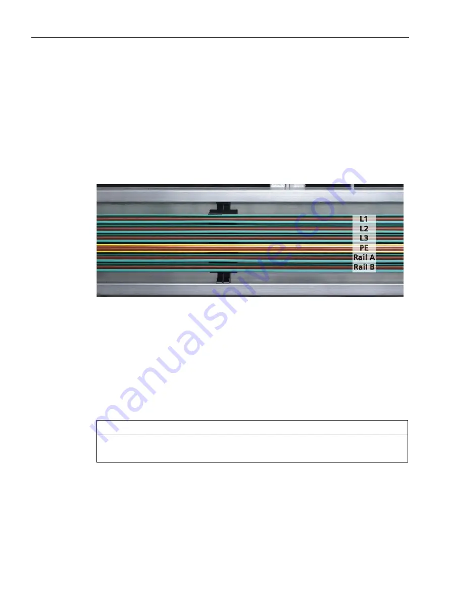
arrangement which is recommended for reliable communication.
Rails: L1, L2, L3, PE, Rail A and Rail B.
Figure 4-3
Arrangement of the rails
It is necessary, however, that except for the regularly grounded PE rail (Page 53), there are
no other rails in addition to the powerline rails (Rail A and Rail B); otherwise, signal couplings
and crosstalk will occur.
The PE rail is also used as shielding in this case. Due to the positioning, the PE rail provides
additional spacing between the live parts with dangerous contact voltage (L1..L3) and the
communication rails Rail A/B. This additional spacing reduces the crosstalk of the
communication signals and the risk of short-circuits.
If additional sliding contact lines are required below the communication rails Rail A and
Rail B, you must separate them with an additional regularly grounded PE rail.
NOTICE
You may use Rail A and Rail B for PL communication only!
Содержание SIMATIC Power Line Booster
Страница 34: ......


