


Application planning
3.6 Mounting cut-out
SIMATIC PC Panel PC 677/877, Control Unit
Operating Instructions, Edition 04/2005, A5E00407724-01
3-7
3.6.2
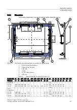
Dimensions
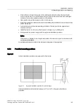
The following illustrations show the dimensions for the installation cut-out.
/
/
/
/
6
6
/
/
6
6
/
/
/
/
/
$
6
/
/
6
6
/
$
$
Figure 3-4
Drill holes for the screws and pressure points for the clamp screws
1
Drill hole for screw attachment
2
Pressure point for clamp
3
setscrews
4
Clamp
5
R
Z
120 in the seal area
6
Seal area
Table 3-1
Measurements for the mounting cut-out in mm
Control units L1 L2 L3
1)
L4
1)
L5
L6
2)
L7
2)
L8
2)
L9
2)
A1 A2 A3
S1 S2 S3 S4 S5
3)
S6
3)
S7
3)
Tolerance
+1 +1 ±0.2 ±0.2 ±0.5 ±0.5 ±0.5 ±0.5 +1
±1 ±1
±1 ±1 ±1 ±1 ±1
±1
±1
key panels
12" TFT
15" TFT
450
450
290
326
465
465
235
279
112
112
—
186
—
135
—
25
—
165
16
16
10
17
1.5
min
to 6
max
78
51
78
51
78
51
78
51
56
56
—
—
—
—
Touch
screen front
12" TFT
15" TFT
19" TFT
368
450
450
290
290
380
—
465
465
—
235
235
112
112
112
—
—
—
—
—
—
—
—
—
—
—
—
16
16
16
10
10
10
1.5
min.
to 6
max
19
81
46
35
81
46
35
81
46
35
81
46
56
56
—
—
—
33
—
—
33


