background image


CP 1604 / CP 1616 
Operating Instructions, 02/2017, C70000-G8976-C218-08 

31


Configuration 


Configuring  

After the communications processor has been installed in the computer, the CP still needs to 

be configured.  
The steps involved are described in the "Commissioning PC Stations" manual. You will find 

the manual on the SIMATIC NET Product DVD in the directory: V2.X.X\CP16xx\doc. 

Downloading firmware 

The CP ships with a current firmware version. 
If you want to use the CP 16xx driver of a current SIMATIC NET CD, new firmware for the 

CP is also supplied with it. The following activities are then necessary: 


Download the firmware to the CP. 


Update and activate the driver of the CP on the PC. 

Description 

This section shows you how to use the firmware loader. 
The Firmware Loader allows you to download new firmware versions to the SIMATIC NET 

modules. 
For more detailed information about the individual download variants, refer to the integrated 

help in the program. 

Firmware 

Here, firmware means the system programs in the SIMATIC NET modules. 

Uses of the Firmware Loader 

The Firmware Loader allows you to download new firmware versions to the SIMATIC NET 

modules. It is used for the following: 


PROFIBUS modules 


Industrial Ethernet modules 


Modules for gateways (for example, IE/PB Link) 

Содержание SIMATIC NET CP 1604

Страница 1: ..._______________ ___________________ ___________________ SIMATIC NET PG PC PROFINET CP 1604 CP 1616 Operating Instructions 02 2017 C70000 G8976 C218 08 Preface Description of the device 1 Hardware installation 2 Configuration 3 Operating hardware 4 Technical specifications 5 Approvals A ...

Страница 2: ...n may be operated only by personnel qualified for the specific task in accordance with the relevant documentation in particular its warning notices and safety instructions Qualified personnel are those who based on their training and experience are capable of identifying risks and avoiding potential hazards when working with these products systems Proper use of Siemens products Note the following ...

Страница 3: ...1 The following components ship with the product CP 1604 communications processor Driver CD for CP 1604 Communications processor CP 1604 EEC 6GK1160 4AT01 The device is suitable for use in environments according to EN50121 The following components ship with the product Communications processor CP 1604 EEC Driver CD for CP 1604 EEC Note Descriptions for CP 1604 EEC All descriptions of the CP 1604 a...

Страница 4: ...616 communications module as well as the CP 1616 onboard communications processor The figures show the module but apply equally to the CP 1616 onboard Validity of this documentation These operating instructions are valid for the following products CP 1604 CP 1616 Note CP 1616 onboard The CP 1616 onboard is an integral part of the SIMATIC PC You will therefore find this information in its documenta...

Страница 5: ...ption of the OPC interface as user programming interface Installation manual SIMATIC NET PC Software This document contains detailed information on installing the SIMATIC net PC software Entry ID 61630923 https support industry siemens com cs ww en view 109488960 System manual Industrial Ethernet Network Manual In this document you will find detailed information on setting up an Industrial Etherne...

Страница 6: ...uctions and Layer 2 Interface This manual introduces you to initial commissioning of the DK 16xx PN IO in Linux the porting of the driver for the CP 1616 and CP 1604 and the porting of the IO Base Library to your target operating system Entry ID 21972491 https support industry siemens com cs ww en view 21972491 SIMATIC NET documentation You will find the entire SIMATIC NET documentation on the pag...

Страница 7: ...eration of plants systems machines and networks In order to protect plants systems machines and networks against cyber threats it is necessary to implement and continuously maintain a holistic state of the art industrial security concept Siemens products and solutions only form one element of such a concept Customer is responsible to prevent unauthorized access to its plants systems machines and n...

Страница 8: ...l knowledge as well as advanced training for individual sectors available at more than 130 locations Courses can also be organized individually and held locally at your location You will find detailed information on the training curriculum and how to contact our customer consultants at the following Internet address www siemens com sitrain SIMATIC NET glossary Explanations of many of the specialis...

Страница 9: ... communications processor 27 2 2 1 Important information 27 2 2 2 Procedure for installing the CP 1616 28 3 Configuration 31 4 Operating hardware 35 4 1 Diagnostics with SNMP 35 4 1 1 SNMP and CP 1616 CP 1604 35 4 1 2 SIMATIC NET SNMP OPC server 36 4 1 3 Variables of the MIB II standard 37 4 1 4 Private MIB of a CP 1616 CP 1604 39 4 2 Web server 40 4 2 1 Web server 40 4 2 2 Language settings 41 4 ...

Страница 10: ...properties of IO routing 74 4 3 9 Configuring IO routing 75 4 4 Media redundancy 75 4 4 1 General description 76 4 4 1 1 Options of media redundancy 76 4 4 1 2 Media redundancy in ring topologies 76 4 4 2 MRP 78 4 4 3 MRP configuration 80 4 4 4 How do I configure media redundancy in a ring topology 83 4 5 Prioritized startup 84 4 6 Eliminating problems 84 5 Technical specifications 87 5 1 Communic...

Страница 11: ...n of the device 1 1 1 CP 1604 communications processor Appearance The following graphic shows the CP 1604 communications processor Note CP 1604 EEC CP 1604 EEC has the same construction The PCB is however varnished and it therefore has greater resistance to environmental influences ...

Страница 12: ...e following significance BF LED SF LED Description off Communications connection is established on Link status error has occurred flashing slowly There are two possible causes An IO device cannot be addressed An IP address was assigned twice off There are two possible causes No fault error A download is in progress on Diagnostics information is available flashing at 2 second in tervals The firmwar...

Страница 13: ... the RJ 45 connection board for CP 1604 This has the Ethernet connectors that allow network operation The signals are processed in the integrated 4 port real time switch of the CP 1604 Ethernet connectors The CP 1604 communications processor is intended for operation in Ethernet networks It also has the following features The connectors are designed for 10BaseT and 100BaseTX via RJ 45 connection b...

Страница 14: ...3 19 TDP_P1 39 M 20 M 40 P3V3 You will find the pin assignment of the connector on the labeling on the ribbon cable socket bar 1 1 2 20 pin male connector for connection of an external power supply Description The 20 pin connector is used to connect an external power supply as well as 2 LEDs for signaling the operating statuses bus fault BF and group fault SF Siemens does not provide an external p...

Страница 15: ...in assignment of the 20 pin connector The pin assignment of the 20 pin connector is as follows Pin no Assignment 1 GND 2 GND 3 5 V power supply 5 4 5 V power supply 5 5 5 V power supply 5 6 5 V power supply 5 7 Connector for SF LED 8 GND 9 Reserved do not assign 10 GND 11 Reserved do not assign 12 GND 13 Connector for BF LED 14 GND 15 5 V power supply 5 16 5 V power supply 5 17 5 V power supply 5 ...

Страница 16: ...ion as a PROFIenergy device With suitable commands from the PROFINET controller the PC in which the CP 1604 is plugged in can be turned off and on again with the aim of reducing energy consumption The device is turned off by certain commands data records on the IO Base user programming interface You will find these commands in the IO Base User Programming Interface document Note Hardware version f...

Страница 17: ...G8976 C218 08 17 Assignment The pin assignment of the 10 pin connector PE is as follows Figure 1 1 View of the 10 pin connector PE X711 from above PIN number Remarks 1 3 3 V 2 PE_WAKE signal 3 Do not connect 4 Do not connect 5 Do not connect 6 Do not connect 7 Do not connect 8 Do not connect 9 Do not connect 10 Ground ...

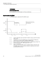
Страница 18: ...own the PC The RST_N level on the PCI bus then falls to Low tpe_wake The firmware receives the PROFIenergy end pause frame and initiates the startup procedure of the host PC with the PE_WAKE signal tpci_unreset When it restarts the host PC pulls the RST_N pin on the PCI bus to High The firmware then sets the PE_WAKE signal back to Low tundefined tundefined 12 seconds After PC start the PE_WAKE sig...

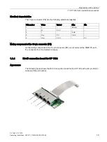
Страница 19: ...PIN number Value Typical Max Min 1 I 20 mA 1 U 3 3 V 2 I 5 mA 2 Ulow 0 V 0 8 V 2 Uhigh 3 3 V 2 V Mating component of the 10 pin connector PE As the mating component of the 10 pin connector PE we recommend the TMM105 xx S D x connector from the Samtec company 1 1 4 RJ 45 connection board for CP 1604 Appearance The following figure shows the RJ 45 connection board for the CP 1604 with a 40 pin ribbo...

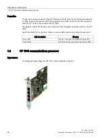
Страница 20: ... the RJ 45 connection board for CP 1604 is connected to the CP 1604 The signals of the 4 RJ 45 jacks are connected to the integrated real time switch on the CP 1604 Apart from the RJ 45 connectors there are also 2 LEDs green and yellow for each port LED description Meaning Green LED Is lit if a connection is established Link LED Yellow LED Is lit when sending and receiving Activity LED 1 2 CP 1616...

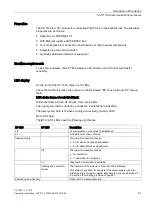
Страница 21: ...Ds in the frame of each RJ 45 jack Within the frame of each RJ 45 jack there are 2 LEDs The upper green LED is lit when a connection is established Link LED The lower yellow LED is lit when sending and receiving Activity LED BF and SF LED The BF and SF LEDs have the following significance BF LED SF LED Description off Communications connection is established on Link status error has occurred flash...

Страница 22: ...e the operating mode LEDs RUN and STOP They do not exist physically but can nevertheless be queried using SNMP They are on in the RUN or STOP mode and never flash normally or quickly External power supply The CP 1616 has a socket for connecting an external power supply With this power supply the integrated real time switch can operate even if the PC is turned off Ethernet The CP 1616 is intended f...

Страница 23: ...ing schematic illustrates a typical application PC with CP 1616 as PROFINET IO controller at the IO controller level The IO Base controller user program runs on the PC and accesses the functions of the IO Base user programming interface The data traffic is handled via a CP 1616 communications processor with several ET 200S SIMATIC S7 PROFINET IO devices via Industrial Ethernet ...

Страница 24: ...ice level There is also a PC with a CP 1616 as PROFINET IO controller a SIMATIC S7 400 with a CP 443 1 as PROFINET IO controller and two SIMATIC S7 ET 200S PROFINET IO devices in the network On the IO device PCs there is an IO Base device user program that accesses the functions of the IO Base user programming interface The data traffic is via a CP 1616 communications processor to a PC as PROFINET...

Страница 25: ...e installing the module read the section Requirements and notes Page 25 in the manual of your PC and the following section completely and keep to the instructions 2 1 2 Requirements and notes Recommendation for installation when using Linux Install the CP 1604 communications processor first and then install the CP 1604 driver Recommendation for installation when using Linux RTAI For the integrated...

Страница 26: ...dresses in the stack are set differently Note With certain variants of the SIMATIC Microbox is not possible to use all module addresses you will find further information on this in the appropriate operating instructions Note Multiple CP 1604 communications processors in one PC are not permitted Note If you use a PCI adapter you should ideally set module address 0 2 1 3 Procedure for installing the...

Страница 27: ...04 modules as described in the section AUTOHOTSPOT 9 Close the computer housing as described in the manual accompanying your PC 10 If required insert the connecting cables TP in the corresponding RJ 45 jacks of the RJ 45 connection board for the CP 1604 11 Plug the power supply connector into the socket again and turn on your computer 2 2 CP 1616 communications processor 2 2 1 Important informatio...

Страница 28: ...put any damaged parts into operation Do not use any parts that show evidence of damage Recommendation for installation when using Linux Install the CP 1616 first and then install the CP 1616 driver Requirements and conditions If available enable the plug and play mechanism in the BIOS of your computer The CP 1616 communications processor requires a PCI slot with master capability Note Note on the ...

Страница 29: ...mly in the socket of the slot 6 Close the computer housing as described in the manual accompanying your PG PC 7 Plug the connecting cable TP into the appropriate socket on the front panel of the CP 1616 8 Plug the power supply connector into the socket again and turn on your computer Note If you insert the CP 1616 in a suitable PCI slot and then secure the metal plate to the housing the module som...

Страница 30: ...Hardware installation 2 2 CP 1616 communications processor CP 1604 CP 1616 30 Operating Instructions 02 2017 C70000 G8976 C218 08 ...

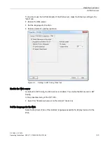
Страница 31: ...so supplied with it The following activities are then necessary Download the firmware to the CP Update and activate the driver of the CP on the PC Description This section shows you how to use the firmware loader The Firmware Loader allows you to download new firmware versions to the SIMATIC NET modules For more detailed information about the individual download variants refer to the integrated he...

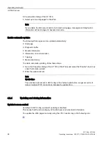
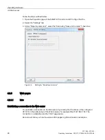
Страница 32: ... compatibility with the device The load file ships with the name fw16xx v v v b b fwl where v v v stands for the version number and b b for the build number Working with the Firmware Loader Depending on the module type the download is prepared and executed in three or four dialog steps For more information refer to the following section and the dialog boxes themselves Starting the firmware downloa...

Страница 33: ...nload can lead to problems Remember that interrupting the download can lead to an inconsistent module status NOTICE Load file used Make sure that the load file you are using is intended as an update for the version of the firmware contained on your module If you are in any doubt contact your local Siemens advisor ...

Страница 34: ... module Status detection You can recognize an inconsistent status on the CP as follows The CP is not accessible with STEP 7 NCM PC in the SIMATIC Manager SIMATIC NCM Manager select configured PC station in the STEP 7 project menu command PLC Edit Ethernet Node The red SF LED group fault flashes at 2 second intervals Following a computer restart all the LEDs of an unused RJ 45 jack light briefly an...

Страница 35: ...s and functions of a device SNMP clients access this information A distinction is made between standardized and private MIBs Standardized MIBs are described in RFC documents Private MIBs contain product specific expansions MIB II describes a set of SNMP variables that is normally supported by all SNMP compliant devices SNMP V1 and SNMP V2 protocols With the SNMP V1 and SNMP V2 protocols all the ob...

Страница 36: ...n 2 RFC 1213 Private MIB MIB with product specific expansions Section Private MIB of a CP 1616 CP 1604 Page 39 4 1 2 SIMATIC NET SNMP OPC server Description The SIMATIC NET SNMP OPC server makes available the SNMP information from TCP IP networks on the OPC interface with SNMP Using the SIMATIC NET SNMP OPC server any OPC client systems can access diagnostics and parameter data of SNMP compliant c...

Страница 37: ...14405 4 1 3 Variables of the MIB II standard Variables in the System directory The following table shows several SNMP variables of the MIB II standard for monitoring the device standard from the System directory Variables Access rights Description sysDescr Read only Contains a vendor specific identification of the device for example SIEMENS SIMATIC NET CP 1616 or CP 1604 A string with up to 255 ch...

Страница 38: ...t The possible value is string with a maximum of 255 characters for example SIEMENS SIMATIC NET CP1616 MLFB HW hardware version FW firmware version Fast Ethernet Port port number Explanation The current value is entered in the pointed brackets Data type DisplayString ifInErrors Read only Number of received packages that were not forwarded to higher protocol layers because of an error Data type Cou...

Страница 39: ...4 4 1 4 Private MIB of a CP 1616 CP 1604 Only variables for the LED status The private MIB contains the following variables for the LED status Variables Access rights Description of the variable Meaning of the values snCp1616BFLedVal snCp1604BFLedVal Read only Status of the bus fault LED Data type for all LED value variables Integer Possible values are as follows 1 LED off 2 LED on 3 LED flashing ...

Страница 40: ...ng object identifier OID iso 1 org 3 dod 6 internet 1 private 4 enterprises 1 siemensAD 4196 adProductMibs 1 simaticNet 1 iCP 9 iCP1616 1 For the CP 1604 The private MIB variables of the CP 1604 have the following object identifier OID iso 1 org 3 dod 6 internet 1 private 4 enterprises 1 siemensAD 4196 adProductMibs 1 simaticNet 1 iCP 9 iCP1604 2 4 2 Web server 4 2 1 Web server Introduction Note I...

Страница 41: ...616 in the Address box of the Web browser in the format http a b c d example of an entry http 192 168 3 141 The Start page of the CP 1616 opens From the Start page you can navigate to the other information Note A maximum of 5 HTTP connections are possible 4 2 2 Language settings Introduction The Web server supports the following languages German Germany English USA Requirements for displaying text...

Страница 42: ...e for display devices in the SIMATIC Manager Select the languages for display devices in the SIMATIC manager Options Language for Display Devices Figure 4 1 Example of language selection for display devices 4 2 3 Settings in HW Config Web tab Requirements You have opened the Properties dialog of the CP 1616 in HW Config ...

Страница 43: ...Set the language for the Web Enable automatic updates optional Figure 4 2 Settings in HW Config Web tab Enable the Web server As default in HW Config the Web server is disabled You enable the Web server in HW Config In the properties dialog of the CP 1616 Select the Enable web server on this module check box Set the language for the Web Select a maximum of two of the installed languages available ...

Страница 44: ...n communication Topology Media redundancy To enable automatic updating follow these steps Go to the Properties dialog of the CP 1616 Web tab and select the Enable check box under Automatic update Enter the update interval Note Update time The activation interval set in HW Config is the shortest update time Larger amounts of data or multiple HTTP connections increase the update time 4 2 4 Updating ...

Страница 45: ...e with the F5 function key or with the following icon Storing messages and diagnostic buffer entries You can store diagnostic buffer entries in a csv file You save the data with the following icon A dialog opens in which you can specify the file name and target directory Note Opening the csv file in Microsoft Excel To display the data correctly in Microsoft Excel do not open the csv file by double...

Страница 46: ...r select the Call during Save and Compile check box Figure 4 3 Setting for Report system error 4 2 6 Web pages 4 2 6 1 Intro Establishing a connection to the Web server You establish a connection to the Web server by entering the IP address of the configured CP 1616 in the address bar of the Web browser for example http 192 168 1 158 The connection is established and the Intro page opens Here we w...

Страница 47: ...server Figure 4 4 Intro To access the pages of the Web server click the ENTER link Note Skipping the Intro Web page Select the Skip Intro check box to skip the Intro In future you will then come directly to the Start page of the Web server To display the Intro again when you start the Web server click the Intro link on the Start page See also Settings in HW Config Web tab Page 42 ...

Страница 48: ...ndicates its current status regarding group errors and bus errors at the time the data was queried The display of the port LEDs is static Figure 4 5 Start page General General contains information about the CP 1616 whose Web server you are currently connected to Status Status contains information about the CP 1616 at the time of the query Reference For information on http connections see the secti...

Страница 49: ...fication Identification The Identification group includes the plant designation location identifier and the serial number The plant designation and location identifier can be configured in the Properties dialog of the CP 1616 General tab in HW Config Order number You will find the order number of the hardware in the Order number box Version You will find the versions of the hardware firmware boot ...

Страница 50: ...c buffer is displayed by the browser on the Diagnostic buffer Web page Figure 4 7 Diagnostic buffer Requirement You have enabled the Web server made the language setting and compiled and downloaded the project with STEP 7 Diagnostic buffer entries 1 100 The diagnostic buffer can hold up to 244 messages Event The Event info box contains the diagnostic events with date and time ...

Страница 51: ...f two languages to be used to display plain language messages 4 Save and compile the project and download the configuration to the CP 1616 Point to note when switching over languages In the top right corner you can switch over the language for example from German to English If you change to a language that you have not configured you will obtain the information as hexadecimal code instead of plain...

Страница 52: ...vices black Component cannot be reached status not available Status not available is always displayed when the CP 1616 is in STOP or during start up evaluation by Report system error for all configured I O modules and I O systems after re starting the CP 1616 This status can however also be displayed temporarily for all modules during operation if there is a flood of diagnostic interrupts No statu...

Страница 53: ...odule levels via the links in the Name column Figure 4 9 Module information Module Module information Depending on the selected level the table shows information on the PC station the DP master system the PNIO master system the nodes the individual modules or even the submodules or components of the station Display of the module levels Via the links you go to the Module information of the higher m...

Страница 54: ...ogy Web page and the device head of the selected module flashes for several seconds Filter You have the option of sorting the table according to certain criteria 1 Select a parameter from the drop down list 2 If applicable enter the value of the selected parameter 3 Click on Filter The filter conditions remain active even after updating a page To disable the filter settings click Filter again Stat...

Страница 55: ...8 55 Example Module information Submodule Figure 4 10 Module information Submodule Example Module information Component Figure 4 11 Module information Component Reference You will find more detailed information on Module information and on the topic of Report system error in the online help of STEP 7 ...

Страница 56: ...Statistics Parameter tab Summarized information about the integrated PROFINET interface of the CP 1616 can be found in the Parameter tab Figure 4 12 Parameters of the integrated PROFINET interface Network attachment Here you will find information identifying the integrated PROFINET interface of the relevant CP 1616 IP parameters Information on the configured IP address and number of the subnet in ...

Страница 57: ...ware 4 2 Web server CP 1604 CP 1616 Operating Instructions 02 2017 C70000 G8976 C218 08 57 Physical properties The Physical properties info box contains the following information Port number Link status Settings Mode ...

Страница 58: ...b server CP 1604 CP 1616 58 Operating Instructions 02 2017 C70000 G8976 C218 08 Statistics tab You will find information on the quality of the data transfer in the Statistics tab Figure 4 13 Characteristic data of data transfer ...

Страница 59: ...luate the quality of the data transfer on the send line based on the statistics in this info box Statistics Port x Received data packages You can evaluate the quality of the data transfer on the receive line based on the statistics in this info box 4 2 6 7 Topology Topology Topology of the PROFINET nodes On the Topology Web page you obtain information about the topological structure and the status...

Страница 60: ...ge from the overview of the PROFINET IO devices to the Topology Web page using the Topology link If there is no set topology configured the actual topology is called up as default Actual topology Displays the current topological structure of the configured PROFINET devices of a PROFINET IO system and the detectable directly neighboring unconfigured PROFINET devices display of the neighbor relation...

Страница 61: ...rating hardware 4 2 Web server CP 1604 CP 1616 Operating Instructions 02 2017 C70000 G8976 C218 08 61 Set topology and actual topology Graphic view Figure 4 14 Graphic view Set topology and actual topology ...

Страница 62: ...on to a passive component The connection is a connection to devices PROFINET devices of a different IO controller or IO subsystem Configured and reachable PROFINET nodes Configured and reachable PROFINET nodes are displayed in dark gray The connections show the ports via which the PROFINET nodes of a station are connected Configured but unreachable PROFINET nodes The configured but unreachable PRO...

Страница 63: ... of another PROFINET IO subsystem is only displayed when it is the immediate neighbor of a configured PROFINET device This is displayed light gray with a dashed line For PROFINET devices of another PROFINET IO subsystem there is no status display in the device head Views when the structure changes If a device fails this device remains in the Set topology view at the same position but has a red bor...

Страница 64: ...y Figure 4 15 Topology Table view Meaning of the icons indicating the status of the PROFINET nodes Icon Meaning Configured and reachable PROFINET nodes Unconfigured and reachable PROFINET nodes Configured but unreachable PROFINET nodes Nodes for which no neighborhood relation could be detected or the neighborhood relation could not be read completely or only incorrectly ...

Страница 65: ...porarily for all modules during opera tion if there is a flood of diagnostic interrupts No status can be obtained for modules of a subsystem connected to a CP green Maintenance required yellow Maintenance demanded red Fault component failed or faulty Fault at a lower module level Topology Status overview The Status overview shows an overview of all PROFINET IO devices PROFINET devices without conn...

Страница 66: ... Media redundancy is deactivated in the ring topology This setting is selected when there is no ring topology MANAGER AUTO CLIENT Select this setting if you use media redundancy in a ring topology and the CP or other Siemens device is the redundancy manager The redundancy manager is then specified automatically by the MRP protocol CLIENT Select this setting if you use media redundancy in a ring to...

Страница 67: ... that of ring port 1 Value Meaning Port 1 BLOCKED The port does not allow any user data to pass through only MRP frames Port 1 DISABLED The port was disabled Port 1 UP The port allows all frames through Port 1 DOWN The port does not have a link Note Configuring in the STEP 7 project As an alternative you can also make this setting in STEP 7 4 3 IO routing This section answers the following questio...

Страница 68: ...trols a robot IO routing makes input output data of the robot controller accessible to an IO controller for the control level that can both read and write the data IO routing is a function that is configured for the IO Base interface When does it make sense to use IO routing The advantages of IO routing are in situations when a complex plant or machine is planned with networked PROFINET IO systems...

Страница 69: ...e two possible ways of writing Writing module oriented All process outputs of a module are written by the IO controller for the control level module oriented Writing bit oriented Individual configured process output bits or bit areas are written by the IO controller for the control level Read process outputs Outputs are always read module oriented This means that the IO controller for the control ...

Страница 70: ... transferred only module oriented If you also use the function for writing outputs bit oriented the data from the process controller user program is mixed with the data of the IO controller for the control level according to the configuration see Section Examples of reading and writing Page 70 Note on the IO Base user programming interface To support IO router functions there are also two diagnost...

Страница 71: ... byte are read by the process controller user program The table and the schematic illustrate that all bits of module 100 can be read by the IO controller for the control level via transfer module 1 I O bits of the IO controller for the control level Transfer relation from the perspective of the IO controller for the control level I O bits of the IO controller for the process level 1 0 read 100 0 t...

Страница 72: ...ten by the process controller user program The IO controller for the control level reads the data The table and schematic show which bits are read by the IO controller for the control level via transfer module 1 I O bits of the IO controller for the con trol level Transfer relation from the perspective of the IO controller for the control level I O bits of the IO controllers for the process level ...

Страница 73: ...erefore configured for address 1 in the transfer module The table and schematic show which bits are written by the IO controller for the control level and which by the IO controller for the process level I O bits of the IO controller for the control level Transfer relation from the perspective of the IO control ler for the control level I O bits of the IO controller for the process level Due to IO...

Страница 74: ... Both IO controllers can read input modules of the process device at the same time Write An output bit can only be written by one of the two IO controllers Two IO controllers can nevertheless write different bits of the same output byte Write read access by the IO controller for the process level to the input output data of the process image is module and byte oriented over the IO Base interface N...

Страница 75: ...rogram In principle the IO router is configured as follows Step Description 1 Configure the CP 1616 As IO device for the IO controller of the control level As IO controller for the process level 2 Configure the IO router Reading input modules is illustrated by example 1 Writing outputs bit oriented is illustrated by example 2 Note For a more detailed description of the configuration of IO routing ...

Страница 76: ...esh networks Parallel connection of transmission paths Closing a linear bus topology to form a ring topology 4 4 1 2 Media redundancy in ring topologies Structure of a ring topology Nodes in a ring topology can be external switches and or the integrated switches of communications modules To set up a ring topology with media redundancy you bring together the two free ends of a linear bus topology i...

Страница 77: ...It does this by sending test frames both from ring port 1 and ring port 2 The test frames run round the ring in both directions until they arrive at the other ring port of the redundancy manager An interruption of the ring can be caused by loss of the connection between two devices or by failure of a device in the ring If the test frames of the redundancy manager no longer arrive at the other ring...

Страница 78: ...t to use MRP may only consist of devices that support this function This applies for example to the following devices Industrial Ethernet switches SCALANCE X 200 as of firmware version V4 0 SCALANCE X 200 IRT as of firmware version V4 0 Communications processors CP 443 1 Advanced 6GK7 443 1GX20 0XE0 as of firmware version V2 0 CP 343 1 Advanced 6GK7 343 1GX30 0XE0 as of firmware version V1 0 Non S...

Страница 79: ...g MRP All the devices connected within the ring topology are members of the same redundancy domain One device in the ring is acting as redundancy manager All other devices in the ring are redundancy clients Non MRP compliant devices can be connected to the ring via a SCALANCE X switch or via a PC with a CP 1616 Prioritized startup If you configure MRP in a ring you must not use the prioritized sta...

Страница 80: ...ow Note Valid MRP configuration In the MRP configuration in STEP 7 make sure that all devices in the ring have a valid MRP configuration before you close the ring Otherwise there may be circulating frames that will cause a failure in the network One device in the ring needs to be configured as redundancy manager and all other devices in the ring as clients Note Note factory settings MRP is disable...

Страница 81: ... leave the setting for Domain as the factory set mrpdomain 1 the defaults for Role and Ring ports also remain active MRP multiple rings If you configure multiple MRP rings the nodes of the ring will be assigned to the individual rings with the Domain parameter Set the same domain for all devices within a ring Set different domains for different rings Devices that do not belong to the same ring mus...

Страница 82: ...settings With brand new Siemens devices and those reset to the factory settings the following MRP role is set Manager Auto CPs Automatic Redundancy Detection SCALANCE X 200 SCALANCE XC 200 SCALANCE XB 200 PROFINET variants SCALANCE XP 200 PROFINET variants SCALANCE X 300 SCALANCE X 400 If you are operating a non Siemens device as the redundancy manager in the ring this may cause loss of the data t...

Страница 83: ...ts are generated if the following errors occur at the ring ports Connection abort on a ring port A neighbor of the ring port does not support MRP A ring port is connected to a non ring port A ring port is connected to the ring port of another MRP domain Status change active passive redundancy manager only If the status changes active passive in a ring a diagnostics interrupt is generated Parameter...

Страница 84: ...ple An industrial robot works with a tool whose actuators are controlled via IO devices It has other tools stored in its magazine When the industrial robot changes tools the prioritized startup property of the IO device is important The faster the IO device is available for data transfer after turning on the power the faster the robot can continue working How do I configure prioritized startup The...

Страница 85: ...ls Following a computer restart all the LEDs of an unused RJ 45 jack light briefly and then go off again Note In contrast to the brief lighting up of the LEDs when the computer starts up the green Link LED always lights up if a cable is inserted in the RJ 45 jack and a link is also established Troubleshooting Download the current firmware file for example fw16xx v v v b b fwl to the CP again via t...

Страница 86: ...Operating hardware 4 6 Eliminating problems CP 1604 CP 1616 86 Operating Instructions 02 2017 C70000 G8976 C218 08 ...

Страница 87: ... of the RJ 45 connection board for CP 1604 40 pin connector Interface of external power supply 20 pin connector Connection to PC PC 104 Plus Voltage PCI power supply 5 VDC 5 5 VDC supply external optional 5 VDC 5 Current consumption PCI voltage at 5 V max 800 mA 5 VDC supply external optional max 800 mA Permitted ambient conditions Operating temperature 5 C to 60 C CP 1604 40 C to 70 C CP 1604 EEC...

Страница 88: ...permitted Note Parallel operation is not permitted Parallel operation of the communications processors CP 1604 CP 1604 EEC and CP 1616 in one PC is not permitted 5 1 1 RJ 45 connection board for CP 1604 Listing The following technical specifications apply to the RJ 45 connection board for CP 1604 Interfaces Connection to 10BaseT 100BaseTx RJ 45 connector four Permitted ambient conditions Operating...

Страница 89: ...3 3 V 5 V 32 bits Voltage PCI power supply 5 VDC 5 Power supply external 6 to 9 VDC Current consumption PCI voltage at 5 V max 800 mA External supply at 6 V max 650 mA External supply at 9 V max 450 mA Permitted ambient conditions Operating temperature 5 C to 70 C Transportation storage temperature 20 to 60 C Construction Module format PC card short PCI format Dimensions H x W x D in mm 167 x 18 x...

Страница 90: ...18 08 Feed in Hollow plug Outer diameter 3 5 mm Inner diameter 1 35 mm WARNING External supply If supplied from a separate source this must meet the requirements to comply with NEC Class 2 Note Parallel operation is not permitted Parallel operation of the CP 1616 and CP 1604 communications processors in one PC is not permitted ...

Страница 91: ...EN 61000 6 3 EN 61000 6 1 Industrial environment EN 61000 6 4 EN 61000 6 2 EC declaration of conformity You will find the EC declaration of conformity for the communications processor on the Product Support pages under the following entry ID 58826997 https support industry siemens com cs ww en view 58826997 C TICK approval The communications processor meets the requirements of the Australian AS NZ...

Страница 92: ...e receiving antenna Increase the separation between the equipment and receiver Connect the equipment into an outlet on a circuit different from that to which the receiver is connected Consult the dealer or an experienced radio TV technician for help Siemens AG is not responsible for any radio television interference caused by unauthorized modifications of this equipment or the substitution or atta...

Отзывы: