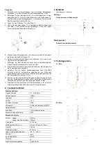
Procedure
1. Unscrew the protective caps from the two mounting screws
③
on the
back of the antenna base plate
④
.
2. Fasten the mounting bracket
①
to the back of the antenna base
plate
④
with two nuts and spring washers
②
. Align the mounting
bracket
①
as shown in the picture. The tightening torque is 3.0 Nm.
3. Place the U-bolt
⑤
around the mast
⑦.
4. Hold the tensioning clamp
⑥
with bent edges pointing to the mast
⑦
and place the tensioning clamp
⑥
over the two ends of the
U-bolt
⑤
through the slotted holes.
5. Attach the mounting bracket
⑧
with the pre-mounted antenna
to the
two ends of the U-bolt
⑨
.
6. Place a spring washer and a nut on each end of the U-bolt
⑨
.
7. Fasten the U-bolt to the mast with the screw nuts. Do not tighten the
nuts yet.
8. Move the antenna to the desired position on the mast. Tighten the
nuts slightly.
9. Attach the flexible connection cable to the SCALANCE W device (not
included) to the N connector socket of the antenna. The maximum
tightening torque for the union nuts is 1.5 Nm.
10. Align the antenna to the desired position by moving it along the oval
hole on the mounting bracket. Tighten the nuts. The tightening torque
is 7.0 Nm.
11. Protect the connectors from environmental influences (e.g. with self-
vulcanizing adhesive tape or a shrink-on hose).
4 Technical data
Electrical data
Frequency range
5.7 to 5.85 GHz
Antenna gain
15 dBic
Impedance
50
Ω
VSWR
1.5: 1
Front-to-back ratio
33 dB
Polarization
circular (RHCP)
Radiation angle
28°
Connector
1x N-connector female
Maximum input power
50 W
Mechanical data
Antenna Length
301 mm
Length, mounted on mast
395 mm
Base plate
Ø 140 mm
Mounting bracket (W x H x L)
44 mm x 19 mm x 115 mm
Weight
0.64 kg
Installation on the mast
Ø 41 mm
Storage and operating temperature
-40
℃
to +60 °C
Degree of protection
IP66
RoHS 2002/95/EC
compliant
Silicone-free
yes
Material of the outer shell
Polycarbonate
5 Dimensional drawing
(dimensions in millimeters)
Antenna
Side and rear view
Mounting bracket
Top and side view
6
Field diagrams
5.7 GHz
5.8 GHz


