background image

Technical specifications 


7.1 Certificates and approvals 


Mobile Client900WXN 

70


Operating Instructions, 04/2015, A5E35883103-AB 

IEC 61131 

The Mobile Client meets the requirements and criteria according to IEC 61131-2:2007, 

Programmable Logic Controllers, Part 2: Equipment requirements and tests. 

KOREA 

The device and the connection box satisfy the requirements according to the Korean 

certification.  
This product satisfies the requirement of the Korean Certification (KC Mark). 


기기는


업무용

(A

전자파


적합기기로서


판매자


또는


사용자는


점을


주의하시기


바라며


가정


외의


지역에서


사용하는


것을


목적으로


합니다

7.1.2


Operating safety 

The HMI device complies with the following standards: 


EN 60204-1 
Safety of Machinery – Electrical Equipment of Machines 


EN 61131-1 and EN 61131-2 
Programmable Controllers 


The HMI device was tested for EMC in accordance with the following standards: 


EN 50081-2, EMC – Unwanted emissions 


EN 61000-6-2, Generic standard, Immunity, industrial environments 


EN 61131-2, Programmable Controllers 

The HMI device also meets the following standards which are important for use within a 

system: 


EN 1921, Industrial automation systems – safety of integrated manufacturing systems 


EN 12417:2001, Machine tools – safety – machining centers 


UL 508, Industrial Control Equipment 


CSA C22.2 No.14, Industrial Control Equipment 

Содержание SIMATIC Mobile Client900WXN

Страница 1: ...__________________ ___________________ SIMATIC HMI Customized Automation Mobile Client900WXN Operating Instructions 04 2015 A5E35883103 AB Preface Overview 1 Safety guidelines 2 Installing and connecting the device 3 Parameter assignment of a Mobile Client 4 Operating the mobile client 5 Device maintenance and repair 6 Technical specifications 7 Technical support A Abbreviations B ...

Страница 2: ...ly by personnel qualified for the specific task in accordance with the relevant documentation in particular its warning notices and safety instructions Qualified personnel are those who based on their training and experience are capable of identifying risks and avoiding potential hazards when working with these products systems Proper use of Siemens products Note the following WARNING Siemens prod...

Страница 3: ...ervice technicians rectify faults that occur during the process control phase Maintenance technicians Maintenance technicians carry out regular maintenance work during the process control phase Knowledge required General knowledge of automation technology and process communication is needed to understand the operating instructions Scope of application of the document This source document was writt...

Страница 4: ...ce for example dialog names and buttons Required inputs for example an IP address Path information File Edit Operating sequences for example menu commands shortcut menu commands F1 Alt P Keyboard actions Please observe notes labeled as follows Note Notes containing important information about the product and its use or a specific section of the documentation to which you should pay particular atte...

Страница 5: ...e device 29 3 1 Preparing for installation 29 3 1 1 Checking delivery 29 3 1 2 Device identification data 29 3 1 3 Mounting positions and type of fixation 30 3 1 4 Preparing for mounting 30 3 2 Connection box and wall bracket 33 3 2 1 Installing the Connection Box compact CA 33 3 2 2 Mounting the wall mounting bracket 33 3 2 3 Mounting and using the magnetic wall mounting bracket 35 3 2 3 1 Mounti...

Страница 6: ...te 61 5 2 Holding and setting down the mobile client 61 5 3 Using the override function 62 5 4 LED display 63 5 5 Switching the device on and off 65 5 6 Possible errors when powering on 66 6 Device maintenance and repair 67 6 1 Cleaning the device 67 6 2 Spare parts and repairs 68 6 3 Recycling and disposal 68 7 Technical specifications 69 7 1 Certificates and approvals 69 7 1 1 Standards certific...

Страница 7: ...ting brackets 80 7 4 4 Ambient conditions for transport and storage 81 7 4 5 Ambient conditions during operation 82 7 4 6 Ambient conditions and degree of protection connection box 83 7 5 Interface description 84 7 5 1 Interface assignment on the Connection Box compact CA 84 7 5 2 Contact assignment of the USB port 84 A Technical support 85 A 1 Service and support 85 A 2 Problem solving 86 B Abbre...

Страница 8: ...Table of contents Mobile Client900WXN 8 Operating Instructions 04 2015 A5E35883103 AB ...

Страница 9: ...ny point of a machine or system The device also has the following additional features Ethernet integrated with connecting cable 9 TFT screen with color depth of 24 bits and a resolution of 1280 768 USB port for service purposes The connection box provides the connection to the power supply and to the Web server in the control cabinet The device is connected to the connection box with a connecting ...

Страница 10: ...eration and monitoring parameter assignment and commissioning to troubleshooting for industrial systems in particular wind turbines Note Please observe the relevant requirements and safety measures for the application and place of use 1 2 Design of the device Front view LED display Display with touch screen Handle Button for brightness control On off button two present ...

Страница 11: ...15 A5E35883103 AB 11 Bottom view Handle Stand The supporting surfaces of the handle and stand are made of anti slip material Rear view Rating plate Space for customized rating plate USB port for service purposes Pressure compensation valve Port for connecting cable with locking clip ...

Страница 12: ...I device 1 DVD with software and documentation with license information and Open Source software 1 packaging Packaging is used for shipping and protection of the device You can reuse the packaging if you are returning the device 1 4 Accessories Accessories are not included with the device You can order accessories by entering the corresponding article number at the following link Industry Mall htt...

Страница 13: ...Circular connector male connector for connection to the connection box The connecting cable is available in the following lengths Length Article number Functional status 5 m 6AV6645 7CY03 1WP0 FS 02 10 m 6AV6645 7CY04 1WP0 FS 02 15 m 6AV6645 7CY05 1WP0 FS 02 The connecting cable is an industrial cable and is therefore resistant to many solvents and lubricants The flexural strength of the connectin...

Страница 14: ...25 2AE03 0CA0 Area for rating plate lasered Interface X1 Positioning mark the connecting cable also has a red mark Align this mark with the mark on the connection box when connecting Interface X10 Connection socket for the connecting cable Only use connecting cables that are approved for the connection box Strain relief bracket Cover cap Connection for equipotential bonding Safety strap ...

Страница 15: ...B 15 1 4 3 Wall mounting bracket The wall bracket ensures secure fastening of the Mobile Panel during stationary operation Hook for the grip on the HMI device Screw flange The wall bracket is not included with the HMI device The wall bracket is available with order number 6AV6574 1AF04 4AA0 ...

Страница 16: ...s The device can fall out of the wall bracket even when handled carefully Never stand below the fitted wall bracket The wall bracket is permitted for indoor use only Do not mount the wall bracket on doors or covers Do not fit the wall bracket anywhere where the device may fall out of the bracket Note The wall bracket is designed for fixed used and is always to be screwed to the wall The wall brack...

Страница 17: ...on ferromagnetic surfaces The following applies to the magnetic holding power Under normal circumstances the wall bracket can be removed from the surface without tools When the wall bracket is used as intended there is no danger of it falling unintentionally with the HMI device The magnetic wall bracket features a retaining mechanism for the HMI device Joint to set the inclination of the device Wi...

Страница 18: ...o not mount the wall bracket on doors or covers The magnetic holding power is affected by the material thickness and structure of the mounting surface Ensure that the holding power at the mounting location is sufficient If necessary choose a different mounting location Risk of injury or damage from magnetic fields Strong magnetic fields attract magnetic parts and damage or destroy electromagnetic ...

Страница 19: ...u wish to adjust the inclination Afterwards tighten the two wing screws Check that the wing screws and the device are tightly in place 1 4 6 Protective cover The protective cover provides mechanical protection of the display and is attached to both handles It protects the device from being damaged when transported for example in a tool bag together with other tools NOTICE Overheating If you use th...

Страница 20: ...AV6645 7CX02 1WP0 1 4 7 Protective foil The protective sheet prevents the touch screen getting scratched or dirty Article number 6AV6645 7CX07 1WP0 Note Particles of dirt can scratch the touch screen when you attach the protective sheet Clean the touch screen before attaching the protective sheet The set contains 10 protective sheets ...

Страница 21: ...ice from slipping You can also use rubber strips to angle the device for example Device 3 rubber strips Article number 6AV6645 7CX01 1WP0 1 4 9 Touch pen The touch pen makes it easier to operate the touch screen The touch pen is to be attached to the connecting cable Touch pen Holder Velcro strap Connecting cable Article number 6FC5348 0AA08 4AA0 ...

Страница 22: ...s The HMI device is part of the operating process The operating process is characterized by the two way communication between controller such as S7 1200 and the operator control and monitoring systems connected to it The following figure shows an exemplary system design The HMI device is solely used for monitoring the operating process To do this the HMI device accesses a Web server which provides...

Страница 23: ...ted program can be restarted normally after voltage dips or power failures Dangerous operating conditions must not occur even temporarily If faults in the system can cause bodily injury or significant property damage additional measures must be taken outside of the system These measures must also ensure safe operating conditions in the system in the event of a fault The system s configuration engi...

Страница 24: ...Siemens are constantly evolving Siemens recommends obtaining regular information regarding product updates For safe operation of Siemens products and solutions appropriate protective measures e g cell protection concept must be taken and each component must be integrated in a comprehensive Industrial Security concept which corresponds with the current state of technology The products of other manu...

Страница 25: ...nt and commissioning to troubleshooting for industrial systems The system consists of the following components Device Connecting cable Connection box Ambient conditions for intended use Industrial environment according to EN 61131 2 2007 Indoor use protected from weather Ambient temperature range 10 to 45 C The connection box is designed as bushing for installation in a control cabinet wall The de...

Страница 26: ...ck the mechanical and climatic environmental conditions according to the following sections Ambient conditions during operation Page 82 Ambient conditions and degree of protection connection box Page 83 NOTICE Climatic factors at the place of use Fluctuations in temperature cause condensation inside the device The device is exposed to heat and to the cold even when not in operation Do not expose t...

Страница 27: ...lace the device on unsteady surfaces It could fall down and be damaged Never expose the device to direct sunlight or heat sources Make sure that the device is sufficiently ventilated Do not cover it Never operate the device with the protective cover on Avoid subjecting the device to mechanical shocks excessive amounts of dust moisture and strong magnetic fields Use with additional measures Example...

Страница 28: ...Safety guidelines 2 2 Notes about usage Mobile Client900WXN 28 Operating Instructions 04 2015 A5E35883103 AB ...

Страница 29: ...ing Retain all enclosed documentation for the entire service life of the HMI device You must pass on the enclosed documentation to any subsequent owner or user of the HMI device Make sure that every supplement to the documentation that you receive is stored together with the original documentation 3 1 2 Device identification data Unpacking the device The device can be clearly identified with the h...

Страница 30: ...x is self ventilated and is approved for all mounting positions Note that the guaranteed protection rating is only ensured if the connecting cable or the dummy cap is plugged into the connection box 3 1 4 Preparing for mounting Selecting the mounting location for the wall mounting bracket Observe the following points when selecting the mounting location Position the wall mounting bracket so that t...

Страница 31: ...ces are required around the wall mounting bracket Mounting position The connection box can be installed in any mounting position IP65 degree of protection is ensured on the front if the following conditions are met Material thickness at the mounting cutout 2 to 6 mm Deviation from plane at the mounting cutout 0 5 mm Surface roughness in the area of the mounting seal 120 µm Rz 120 ...

Страница 32: ... Instructions 04 2015 A5E35883103 AB Mounting cutout and clearances Mounting cutout Clearance at rear Clearance in front All dimensions in mm Mounting depth of the connection box 30 mm Keep in mind that a clearance is required at the rear for the cables and connectors in addition to the mounting depth ...

Страница 33: ...ection box Do not install a connection box with a damaged mounting seal 2 Insert the connection box in the mounting cutout Secure the connection box to prevent it from falling out 3 Place one mounting clip into each of the four cutouts marked 4 Fasten the mounting clips The permitted torque is 0 2 Nm 3 2 2 Mounting the wall mounting bracket Requirement In order to ensure that the HMI device can be...

Страница 34: ...les NOTICE Risk of injury from the wall bracket People may bang in to the wall bracket This can result in injury and in damage to the device Select a position for the wall bracket where no individuals are placed at risk Procedure 1 Place the wall bracket on the mounting surface 2 Mark the mounting holes with a marking tool 3 Drill 3 through holes or 3 threaded holes M5 4 Attach the wall bracket ...

Страница 35: ...et where no persons are placed at risk Overhead mounting is not permitted Mounting at locations at which the wall bracket or devices held in it could fall is not permitted Check for any dirt before mounting the magnets Ensure that the mounting surface is clean and suitable Curved surfaces are permitted up to a curve radius of 1 5 m Ensure that the whole surface of all magnets is in contact with th...

Страница 36: ...he magnetic wall bracket The device will slide into the lock position 3 Release the lock hook 4 Check to make sure that the device is completely engaged in the magnetic wall bracket NOTICE Device can drop In the case of improper locking the device could fall out of the wall bracket and get damaged Make sure that the lock hook is latched on the device Taking the device out of the magnetic wall brac...

Страница 37: ...lation in a control cabinet Please observe the relevant guidelines for control cabinet construction at the place of use Make sure that all the connectors and cables have sufficient contact and strain relief The two LEDs at the RJ45 socket are not supported by the hardware and are not illuminated during operation Requirement The connection box is mounted in accordance with the specifications of the...

Страница 38: ...ts The following information must therefore be observed when installing the equipotential bonding The effectiveness of equipotential bonding increases as the impedance of the equipotential bonding conductor decreases or as its cross section increases If two plant sections are interconnected by means of shielded data cables and their shielding is connected at both ends to the grounding protective c...

Страница 39: ... conductors Ensure there is sufficient cable cross section Otherwise there is a risk that interface components will be damaged or destroyed Connection graphic The figure below shows how to connect the equipotential bonding of the connection boxes to the equipotential busbars Ground connection Equipotential bonding conductor cross section 1 5 mm2 Equipotential busbar Ethernet cable Equipotential bo...

Страница 40: ...e connection box Safe electrical isolation according to IEC 60364 4 41 or HD 384 04 41 VDE 0100 Part 410 The power supply provides safety extra low voltage according to SELV PELV up to a maximum of 36 V DC and also does not exceed m 36 V DC in case of fault Refer to the information in the data sheet for overvoltage protection in the event of an internal error or take appropriate voltage limiting m...

Страница 41: ...functional ground of the connection box Connect the equipotential bonding conductor of the connection box as described in the section Equipotential bonding of the connection box Page 38 Note Applies to non isolated system design Connect the terminal for GND 24 V from the 24 V power supply output to equipotential bonding for uniform reference potential 4 Connect cables M24 and P24 to the power supp...

Страница 42: ...e to the fastening element which is labeled in the figure below similar 3 3 1 5 Connecting the Web server Configuration diagram Connecting a Web server to a connection box The figure below shows the connection of a Web server to the connection box and a Mobile Client Note Damage to the HMI device Only connect the HMI device to public Ethernet networks using a switch or comparable device ...

Страница 43: ...down the locking clip until it slots into place on the connector 4 Align the red dot on the connecting cable connector with the red dot on the mobile client socket 5 Insert the connector into the socket and push until it clicks into place 6 Swing down the locking clip until it slots into place on the connector CAUTION Incorrectly plugged in connectors cause malfunctions If the connecting cable con...

Страница 44: ...till does not go out send the device for repair Remove connector You can remove the connecting cable at the connection box and or at the device 1 Lift up the connecting cable locking clip at the device 2 To disconnect the connecting cable from the device pull firmly on the connecting cable connector 3 Lift up the connecting cable locking clip at the connection box 4 To remove the connecting cable ...

Страница 45: ...anently records data in case service is required The Maintenance website is displayed under the following conditions When the device is initially started with the factory settings When no start option is selected When a start option is not possible or cannot be achieved When the operator presses both buttons for brightness control simultaneously When the following fixed address of the Maintenance ...

Страница 46: ...lick Apply Config Reboot The device restarts and activates the new settings 4 2 Opening a customer specific website If there is a connection to the web server the customer specific website is displayed If you want to open the Maintenance website from the customer specific website a corresponding button or hyperlink must be configured see section Maintenance website Requirement The device is switch...

Страница 47: ...low includes the icons of the Maintenance website with links to the relevant sections Icon Functional description Network Settings page Page 48 Webbrowser Configuration page Page 49 Calibration page Page 51 Certificates are currently not supported Update page Page 52 Admin page Page 53 Start Options page Page 55 Q Data page Page 57 Export Load Settings page Page 59 ...

Страница 48: ...al network However you cannot for example access files of the HMI device from a PC via the local network Type of address assignment To obtain the addresses automatically via DHCP select Automatic IP Address To determine the addresses manually select Static Address If you have selected manual address assignment enter the corresponding addresses under IP Netmask and under Gateway as required NOTICE ...

Страница 49: ...015 A5E35883103 AB 49 4 5 Webbrowser Configuration page On the Webbrowser Configuration page you can specify the screen and keyboard display in the Web browser Use Zoom factor to enlarge or reduce the entire screen content zoom factor 70 160 in 10 increments Use Show scroll bars to activate and deactivate the scroll bars ...

Страница 50: ...g Instructions 04 2015 A5E35883103 AB Use the OnScreenKeyboard Layout options to specify the layout of the on screen keyboard QWERTY for English keyboard QWERTZ for German keyboard Chinese simplified for Chinese keyboard You can enter Latin characters when you press the X key twice on the Chinese keyboard ...

Страница 51: ...ed to calibrate the touch screen Requirement 1 Touch pen The Calibration dialog is open Procedure 1 Select Start Calibration The following dialog appears 2 Briefly touch the center of the calibration crosshairs The calibration crosshairs are then displayed at three more positions Briefly touch the middle of the calibration crosshairs for each position Once you have touched the calibration crosshai...

Страница 52: ...r FAT32 partition The ongoing update procedure cannot be explicitly aborted The update process is canceled when you interrupt the power supply or pull the USB cable The existing image will still start up without any problems Update from URL The update via URL is performed via HTTP with the syntax http s 149 202 10 10 The URL is checked for validity A search is performed for a fw tar file at this p...

Страница 53: ... all functions see section Maintenance website NOTICE Unrestricted access An unrestricted user can manipulate data This can result in damage to the machine or system Protect your device from unauthorized access Always assign a password Change your password You use a password to protect your device from unauthorized access see also section Security instructions 1 To change the password log on as ad...

Страница 54: ...h password fields blank when you change the password All functions are available without logon after restart with Apply Config Reboot Log on and log off as administrator When the user is not logged on as administrator logged off only the following functions are available Admin Calibration Q Data Upgrade 1 To log on as administrator press Admin The following page opens 2 Enter the password If the p...

Страница 55: ...d is displayed The URL is not checked for validity If the website or the web server is unavailable during the start the Maintenance website is displayed Customer specific welcome page The custom html file is looked up in the root directory of the USB stick loaded and processed by the browser The file must not be larger than 1 MB An error is displayed if the file is too large The Maintenance websit...

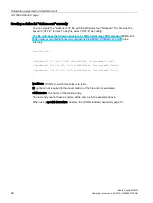
Страница 56: ... standard ECMA 404 http www ecma international org publications files ECMA ST ECMA 404 pdf in the Internet stationlist ipaddress 1 2 3 4 id 1406896505961 stationname aaa ipaddress 1 22 33 44 id 1406896515846 stationname bbb ipaddress 111 32 3 4 id 1407155369801 stationname ccc ipaddress IP URL to which this entry is to refer id optional not required for manual creation of the file and not evaluate...

Страница 57: ... Serial no of the device Operating system version Device image and BIOS version Boot loader version Firmware version of the power supply board SMM MAC address and IP address The device is also equipped with an internal operating data recording system which is active in all standard operating states see below The following data is permanently stored for evaluating use for servicing purposes Device ...

Страница 58: ...es and device switched on CPU PwrCycles Entries shows how often the device switched to this temperature range for each operating state Example How often did the device switch to the temperature range while there was voltage at the device SMM Entries or the device CPU Entries was running Note PwrCycles and Entries adjust the data under Time in a temperature range Example Where the total operating t...

Страница 59: ...ge is output if an error occurs and the file is discarded If there is no error the device is restarted and the new settings are activated You must be logged on as administrator for this function Export settings to USB Device and restart The latest maintenance settings are stored in the root directory in the syssettings conf file Reset to Factory Restore the factory settings A confirmation page wit...

Страница 60: ...Parameter assignment of a Mobile Client 4 11 Export Load Settings page Mobile Client900WXN 60 Operating Instructions 04 2015 A5E35883103 AB ...

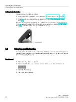
Страница 61: ...on Parameter assignment Mobile Client You can open an on screen keyboard for inputs on the customer specific website as well as the Maintenance website see section Webbrowser Configuration page Page 49 You can enter Latin characters when you press the X key twice on the Chinese keyboard See also Maintenance website Page 45 5 2 Holding and setting down the mobile client Holding the device The figur...

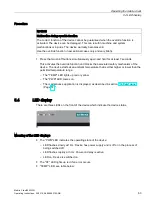
Страница 62: ... within reach you can also set down the device as shown below after attaching the three rubber strips according to section Rubber strips Page 21 The rubber strips keep the device from slipping 5 3 Using the override function You can use the Override function when the device is operated at an ambient temperature outside the permitted range The operator has to make this decision The use of the overr...

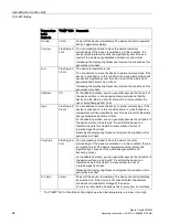
Страница 63: ...erride function and blocks the associated safety mechanism of the device The device starts at an ambient temperature that is either higher or lower than the permitted temperature range The TEMP LED lights up red or yellow The PWR LED comes on The maintenance application is displayed as described in section Q Data page Page 57 5 4 LED display There are three LEDs on the front of the device which in...

Страница 64: ... are advised to move the device to cooler surroundings If the device is switched on in this condition there is a risk that device temperature will rise significantly over time as a result of the waste heat generated and become critical For handheld operation you can generally assume that all parts of the device surface are below 43 C and that the device can therefore be held for at least 5 minutes...

Страница 65: ...CE Device switches off automatically after 48 hours The device switches off automatically once it has been idle for 48 hours This can result in machine and system malfunctions Please consider this response when operating the device The device starts in full screen mode Shutdown the device 1 Close the project on the HMI device before shutting it down 2 Press the two on off buttons simultaneously an...

Страница 66: ...rating temperature is outside the permitted range according to the section Problem solving Page 86 This is displayed as follows The TEMP LED lights up red The PWR LED flashes at 3 Hz The device is in the Power on delay state The device switches on automatically as soon as the operating temperature is in the permitted range Wait until the permitted operating temperature has been reached This is dis...

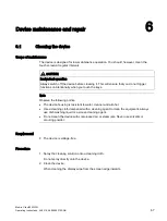
Страница 67: ...tions unintentionally when you touch the keys Note Observe the following points The device housing is resistant to water cleaner and alcohol Use a cleaning cloth dampened with a cleaning agent to clean the equipment Always use dish washing liquid or a screen cleaning agent Do not clean the device with compressed air or steam jets Never use solvents or scouring powder Requirement The device is volt...

Страница 68: ... the Center may decide to give you a credit A credit is only granted when the sender ordered a new HMI device The address is Siemens AG Digital Factory Returns Center Siemensstr 2 D 90766 Fürth Germany Spare parts Spare parts and accessories for the HMI device can be found in section Accessories Page 12 6 3 Recycling and disposal The HMI devices described in these operating instructions can be rec...

Страница 69: ...ropean standards promulgated in the Official Journals of the European Community for programmable logic controllers 2004 108 EC Electromagnetic Compatibility Directive EMC Directive EC Declaration of Conformity The EC Declarations of Conformity are available to the relevant authorities at the following address Siemens AG Digital Factory Factory Automation DF FA SE R D Breslauer Str 5 DE 90766 Fürth...

Страница 70: ...에서 사용하는 것을 목적으로 합니다 7 1 2 Operating safety The HMI device complies with the following standards EN 60204 1 Safety of Machinery Electrical Equipment of Machines EN 61131 1 and EN 61131 2 Programmable Controllers The HMI device was tested for EMC in accordance with the following standards EN 50081 2 EMC Unwanted emissions EN 61000 6 2 Generic standard Immunity industrial environments EN 61131 2 Prog...

Страница 71: ...interference The following table shows the electromagnetic compatibility of modules with regard to pulse shaped interference This requires the HMI device to meet the specifications and directives for electrical installation Pulse shaped interference Test voltage Degree of severity Electrostatic discharge in accordance with IEC 61000 4 2 Air discharge 8 kV Contact discharge 6 kV 3 Bursts high speed...

Страница 72: ... 1 GHz On 3 V m in the range of 1 4 GHz to 2 GHz On 1 V m in the range of 2 GHz to 2 7 GHz 10 V m with 50 pulse modulation At 900 MHz At 1 89 GHz 3 RF interference current on cables and cable shielding IEC 61000 4 6 Test voltage 10 V at 80 amplitude modulation of 1 kHz in the range from 10 kHz to 80 MHz 3 Emission of radio interference The following table shows the emitted interference from electr...

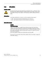
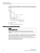
Страница 73: ...GB Elektrostatisch Gefährdete Bauteile Baugruppen Germany ESD Electrostatic Sensitive Device internationally recognized term Electrostatic charging NOTICE Electrostatic charging ESDs may be destroyed by voltages far below the level perceived by human beings Voltages of this kind develop when a component or an assembly is touched by a person who is not grounded against static electricity Usually it...

Страница 74: ... NOTICE Observe grounding measures When working with electrostatic sensitive devices make sure that the person the workplace and the packaging are properly grounded This helps to avoid electrostatic charging As a rule only touch the ESD if this is unavoidable for example for maintenance When you touch modules make sure that you do not touch the pins on the modules or the PCB tracks In this way the...

Страница 75: ...Technical specifications 7 3 Dimension drawings Mobile Client900WXN Operating Instructions 04 2015 A5E35883103 AB 75 7 3 Dimension drawings 7 3 1 Mobile client Front side and rear view ...

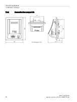
Страница 76: ...Technical specifications 7 3 Dimension drawings Mobile Client900WXN 76 Operating Instructions 04 2015 A5E35883103 AB 7 3 2 Connection Box compact CA ...

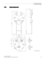
Страница 77: ...Technical specifications 7 3 Dimension drawings Mobile Client900WXN Operating Instructions 04 2015 A5E35883103 AB 77 7 3 3 Wall mounting bracket ...

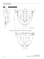
Страница 78: ...cal specifications 7 3 Dimension drawings Mobile Client900WXN 78 Operating Instructions 04 2015 A5E35883103 AB 7 3 4 Magnetic wall bracket The figure below shows the rear view with the position of the magnet ...

Страница 79: ...e Isolation resistance is demonstrated in the type test with the following test voltages in accordance with IEC 61131 2 Circuits with a rated voltage of Ue relative to other circuits or ground Test voltage 50 V 500 V DC Display Type Color TFT LC Display Size 9 inch Resolution WXGA resolution 1280 768 Color depth 24 bits Brightness control Yes Backlighting Half brightness life time typical LED 5000...

Страница 80: ...mum Inrush current I2t Approx 700 mA Approx 850 mA Approx 0 6 A2s 24 V DC output X10 pin 4 driver ability Signal High Device connected self limited max 100 mA Signal Low Device not connected Protection class and degree of protection The device meets the requirements of EN 61131 2 Circuits with rated voltage of Vi Test voltage 50 V 500 V AC to other circuits to ground The device meets the requireme...

Страница 81: ... to 660 hPa corresponds to an elevation of 1000 to 3500 m Relative humidity 5 to 95 without condensation Sinusoidal vibration in accordance with IEC 60068 2 6 5 to 8 4 Hz 3 5 mm 8 4 to 150 Hz 9 8 m s2 Shock in accordance with IEC 60068 2 27 25 g 6 ms 1000 shocks per axis Note In the following cases ensure that no humidity can settle on or in the HMI device Transportation of the HMI device in low t...

Страница 82: ... to reduce amplitudes or acceleration In such situations use vibration damping or vibration absorber systems Climatic ambient conditions The following tables show the permissible climatic ambient conditions for use of the Mobile Client and connection box Mobile Client Note Observe the following points The SIMATIC Mobile Client can be exposed to an ambient temperature of about 10 C due to its inter...

Страница 83: ...vice has a vapor permeable valve which gives a certain amount of protection from condensation inside the device 7 4 6 Ambient conditions and degree of protection connection box Ambient conditions The Connection Box compact CA is specified according to IEC 61131 2 or UL508 as Open Type Permissible ambient temperature range for transport and storage 20 to 60 C Permissible ambient temperature range d...

Страница 84: ...X1 Pin Assignment Pin Assignment Pin Assignment Pin Assignment 1 TD 3 RD 5 Not connected 7 Not connected 2 TD 4 Not connected 6 RD 8 Not connected X10 The pins are numbered from bottom to top Pin Assignment 1 Functional earth 2 M24 3 P24 4 24 VDC when device is connected 5 12 Not connected 7 5 2 Contact assignment of the USB port USB socket Contact Assignment 1 5 VDC out max 500 mA 2 USB DN 3 USB ...

Страница 85: ...s information system for SIMATIC PC PG http www siemens com asis SIMATIC Documentation Collection http www siemens com simatic tech doku portal Your local representative http www siemens com automation partner Training center http www sitrain com Industry Mall https mall industry siemens com When contacting your local representative or Technical Support please have the following information at han...

Страница 86: ...er the connecting cable has been fully plugged in to the HMI device and the connection box Humidity too high condensation Let the device dry for about 4 hours Only the SF LED is on Internal error or voltage outside permissible range Check the power supply or remove the device from the power supply Switch on the power supply again If the error still exists send the device to the Return Center in Fü...

Страница 87: ...D Ground HF High Frequency HMI Human Machine Interface IEC International Electronic Commission IP Internet Protocol IPC Industrial PC LED Light Emitting Diode PC Personal Computer PELV Protective Extra Low Voltage RFN Runtime TIA Portal V13 Full Features Non arctic hardware with buttons no heating SELV Safety Extra Low Voltage SMM System Management Module TFT Thin Film Transistor UL Underwriter s ...

Страница 88: ...Abbreviations B 1 Abbreviations Mobile Client900WXN 88 Operating Instructions 04 2015 A5E35883103 AB ...

Страница 89: ...t are indicated by means of graphic elements or by indicator lamps on the HMI device The operator controls of the HMI device allow the operator to interact with the processes of the machine or plant Plant General term referring to machines processing centers systems plants and processes which are operated and monitored on an HMI device PLC A PLC is a general term for devices and systems with which...

Страница 90: ...Glossary Mobile Client900WXN 90 Operating Instructions 04 2015 A5E35883103 AB ...

Страница 91: ... bonding 38 USB devices 44 Connecting cable Connecting 43 Connection box Clearance 31 33 Connecting 38 EMC compliant installation 71 LED display 63 Mounting position 30 Connection graphic Equipotential bonding 39 Connection sequence 38 Conventions 4 D Degree of protection Protection against ingress of solid foreign bodies 80 Protection against water 80 DHCP 48 Display Technical specifications 79 D...

Страница 92: ... Bottom view 11 Front view 10 Rear view 11 Mobile Client Applications 10 Holding 61 Interface 79 Mounting position 30 Shutdown 65 Switching on 65 Technical specifications 79 Testing 65 Mounting Magnetic wall bracket 35 Mounting location Wall mounting bracket 30 Mounting position Connection box 30 HMI device 31 Mobile Client 30 Wall bracket 34 N Name server 48 Net mask 48 O Open Maintenance 45 Oper...

Страница 93: ...ge conditions 81 Supply voltage 80 Switching on Mobile Client 65 T Technical specifications Display 79 Memory 79 Mobile Client 79 Supply voltage 80 Weight 80 Testing Mobile Client 65 Touch screen Calibrating 51 Transport conditions 81 Transport damage 29 U UL approval 69 Usage Conditions 26 In residential areas 26 Industrial 26 Mobile Client 10 With additional measures 27 USB devices Connecting 44...

Страница 94: ...Index Mobile Client900WXN 94 Operating Instructions 04 2015 A5E35883103 AB ...
Отзывы: