PDC1000(F)
18
Equipment Manual, 02/2020, A5E48775040-AA
Connecting
3
3.1
Terminal assignment
Connection options on the PDC1000
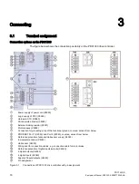
The figure below shows the connection possibility on the PDC1000 drive controller.
①
Power supply of power unit (X5050)
②
Logic supply of PDC (X5060)
③
Hardware STO (X5060)
④
SSI absolute encoder (X5060)
⑤
External braking resistor (X5051)
⑥
Motor phases (X5055)
⑦
Connection for grounding strap of the functional ground, covered, access from below
⑧
PROFINET Port 1 (X2050) and Port 2 (X2060), covered, access from below
⑨
Reference potential of encoder/Hall sensor supply (X4050)
⑩
Incremental encoder (X4050)
⑪
Hall sensor (X4050)
⑫
Wiring duct for connection cables, e.g. connection cable for motor brake
⑬
Reference potential of digital inputs/outputs (X4060)
⑭
2 digital outputs (X4060)
⑮
4 digital inputs (X4060)
⑯
Supply of inputs/outputs (X4060)
⑰
Pin assignment
Figure 3-1
Connections of PDC1000 drive controller with pin assignment
Содержание SIMATIC MICRO-DRIVE PDC1000
Страница 1: ...PDC1000 F ...


