background image

Technical specifications 


8.2 Directives and declarations 


SIMATIC IPC277G 

74


Operating Instructions, 08/2021, A5E50059956-AA 

8.2.2


RoHs directive 

This product meets the requirements stated in the RoHS directive (Restriction of Hazardous 

Materials): 2011/65/EU  
Compliance with the directive has been reviewed according to the following standard: EN 

IEC63000 

8.2.3


ESD guideline 

What does ESD mean?  

An electronic module is equipped with highly integrated components. Due to their design, 

electronic components are highly sensitive to overvoltage and thus to the discharge of static 

electricity. Such electronic components or modules are labeled as electrostatic sensitive 

devices. 
The following abbreviations are commonly used for electrostatic sensitive devices: 


ESD – Electrostatic sensitive device 


ESD – Electrostatic Sensitive Device as a common international designation 

Electrostatic sensitive devices can be labeled with an appropriate symbol. 


NOTICE 
Damage to ESD from touch 

Electrostatic sensitive devices, ESD, can be destroyed by voltages which are far below the 

human perception limit. If you touch a component or electrical connections of a module 

without discharging any electrostatic energy, these voltages may arise. 
The damage to a module by an overvoltage can often not be immediately detected and only 

becomes evident after an extended period of operation. The consequences are incalculable 

and range from unforeseeable malfunctions to a total failure of the machine or system. 
Avoid touching components directly. Make sure that persons, the workstation and the 

packaging are properly grounded. 


Charge 

Every person without a conductive connection to the electrical potential of his/her 

surroundings can be electrostatically charged. 
The material with which an electrostatically-charged person comes into contact is of 

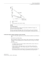
particular significance. The figure shows the maximum electrostatic voltages with which a 

person is charged, depending on humidity and material. These values conform to the 

specifications of IEC 61000-4-2. 

Содержание SIMATIC IPC277G

Страница 1: ... 1 Safety instructions 2 Installing and connecting the device 3 Commissioning the device and device functions 4 Operating the device 5 Expanding and assigning parameters to the device 6 Maintaining and repairing the device 7 Technical specifications 8 Technical support A Markings and symbols B List of abbreviations C ...

Страница 2: ...by personnel qualified for the specific task in accordance with the relevant documentation in particular its warning notices and safety instructions Qualified personnel are those who based on their training and experience are capable of identifying risks and avoiding potential hazards when working with these products systems Proper use of Siemens products Note the following WARNING Siemens product...

Страница 3: ...commended Validity of the operating instructions These operating instructions are valid for all versions of the SIMATIC IPC277G The updates of the document will be published on the Siemens Industry Online Support https support industry siemens com cs ww en view 109744171 Scope of this documentation The documentation for the SIMATIC IPC277G consists of Product information Important notes on your de...

Страница 4: ...Preface SIMATIC IPC277G 4 Operating Instructions 08 2021 A5E50059956 AA History The following editions of these operating instructions have been published Edition Comment 08 2021 First edition ...

Страница 5: ...Preparing for installation 19 3 1 1 Checking the delivery package 19 3 1 2 Identification data of the device 20 3 1 3 Permitted mounting positions 22 3 1 4 Preparing the mounting cutout 23 3 2 Mounting the device 24 3 2 1 Mounting instructions 24 3 2 2 Secure with mounting clips 26 3 2 3 Fastening a device using a VESA adapter 29 3 3 Connecting the device 31 3 3 1 Notes on connecting 31 3 3 2 Conn...

Страница 6: ...ntervals 57 7 2 Repair information 57 7 3 Cleaning the Device Front 58 7 4 Installing and removing hardware 60 7 4 1 Replacing the backup battery 60 7 4 2 Replacing the memory module 62 7 5 Reinstalling the operating system 66 7 5 1 Installing the drivers and software 66 7 6 Recycling and disposal 69 8 Technical specifications 70 8 1 Certificates and approvals 70 8 2 Directives and declarations 73...

Страница 7: ... interface 95 8 5 3 4 LVDS interface 97 8 5 3 5 Backlight interface 98 8 5 4 System resources 98 8 5 5 Input output address areas 99 8 5 5 1 Overview of the internal module registers 99 8 5 5 2 Watchdog control register 99 8 5 5 3 Watchdog counter register 99 8 5 5 4 Watchdog state register 100 8 5 5 5 Battery status register 100 8 5 5 6 NVRAM address register 100 8 6 BIOS description 101 8 6 1 Ov...

Страница 8: ...on possibility SIMATIC IPC277G is available with various operating units that differ with regard to the display size This display is a color display with a backlit wide screen format TFT color display Displays are available in the following sizes for the SIMATIC IPC277G 7 multi touch screen 10 multi touch screen 12 multi touch screen 15 multi touch screen 19 multi touch screen 22 multi touch scree...

Страница 9: ...net 3 RJ45 Ethernet 10 100 1000 Mbps The device with the Intel Atom x6414RE Processor supports TSN COM optional 2 RS232 RS422 RS485 2 USB external 4 USB 3 1 Gen2 up to 10 Gb s USB internal 2 USB2 0 500 mA pin header DisplayPort Connection of a digital monitor support DisplayPort Standard Version 1 4 2 DP 3 support resolution up to 4096 2160 pixels at 60 Hz Keyboard mouse Connection through USB por...

Страница 10: ...evices 1 2 1 7 and 10 multi touch devices This section describes the design of the 7 and 10 devices using the 7 device as an example Front view and side view Display touch screen Recesses for mounting clips Mounting seal Bottom view M 2 SSD card slot Interfaces and operating elements Recesses for mounting clips Product label ...

Страница 11: ...bes the design of 12 15 19 22 and 24 multi touch devices using the 19 device as an example Front view and side view The front view on the left is the standard mounting position side view on the right Display touch screen Recesses for mounting clips Mounting seal Bottom view M 2 SSD card slot Interfaces and operating elements Recesses for mounting clips Product label ...

Страница 12: ...232 RS422 RS485 D sub connector LAN X1P1 X2P1 X3P1 3 RJ45 Ethernet connections for 10 100 1000 Mbps USB 3 1 port X62 X63 2 USB 3 1 port high current 1 2 4 12 15 19 22 and 24 devices Interfaces and operator controls Power supply Connection for a 24 VDC power supply On Off switch Switch on position Switch off position C Protective conductor Connection for protective conductor M 2 SSD slot X50 Slot f...

Страница 13: ...es Accessories available for order Accessories Article number Strain relief set cable and plug Size 7 to 10 6ES7648 1AA50 0XN0 Strain relief set cable and plug Size 12 to 24 6ES7648 1AA50 0XP0 M 2 Key B to Key E adapter 6ES7648 1AA50 0XR0 Dust protection set 6ES7648 1AA50 0XG0 Lithium battery A5E48370874 Strain relief The cable strain relief set contains 5 pieces cable strain relief 5 pieces Ether...

Страница 14: ...Overview 1 3 Accessories SIMATIC IPC277G 14 Operating Instructions 08 2021 A5E50059956 AA Other accessories Touch stylus only for devices with capacitive multi touch screen ...

Страница 15: ...ult in death or serious injury Ensure that only suitably qualified personnel perform the work WARNING The equipment is designed for operation with Safety Extra Low Voltage SELV or Protective Extra Low Voltage PELV This means that electrical circuit in which the voltage cannot exceed 30 VAC RMS 42 4 VAC peak or 60 VDC under NORMAL CONDITIONS and CONDITIONS OF A SINGLE FAULT including ground faults ...

Страница 16: ...201 the device is classified as Open equipment Open equipment must be installed within an enclosure which protects you from hazards including mechanical hazards electrical shock and spread of fire Battery WARNING Risk of explosion and release of harmful substances Improper handling of lithium batteries can result in an explosion of the batteries Explosion of the batteries and the released pollutan...

Страница 17: ...bserve the information on electromagnetic compatibility in the technical specifications ESD Guideline Label electrostatic sensitive devices with the ESD symbol NOTICE Electrostatic sensitive devices ESD When you touch electrostatic sensitive components you can destroy them through voltages that are far below the human perception threshold If you work with components that can be destroyed by electr...

Страница 18: ... this SIMATIC product The product does not process save any personal information but only technical functional data e g time stamps If the user links this data to other data e g shift plans or if the user saves personal information on the same medium e g hard disk and therefore creates a personal reference in the process the user has to ensure meeting the guidelines regarding data protection 2 4 D...

Страница 19: ...iately 3 Unpack the device at its installation location 4 Keep the original packaging in case you have to transport the unit again 5 Check the contents of the packaging and any accessories you ordered for completeness and damage Note Damage to the device during transport and storage If a device is transported or stored without packaging shocks vibrations pressure and moisture may impact the unprot...

Страница 20: ...eather moisture could build up on or inside the device Moisture causes a short circuit in electrical circuits and damages the device In order to prevent damage to the device proceed as follows Operation and store the device in a dry location Bring the device to room temperature before starting it up Do not expose the device to direct heat radiation from a heating device If condensation develops wa...

Страница 21: ...led Windows operating systems have COA labels Ethernet address 1 MAC Product label Ethernet address 2 MAC Ethernet address 3 MAC Product label The following image shows the product label on the SIMATIC IPC277G as an example COA label Microsoft Windows Product Key on the Certificate Of Authenticity COA The COA label is only attached to the rear of the device containing a preinstalled and activated ...

Страница 22: ...rature at the device Comment Load 7 and10 12 and 15 19 22 and 24 M 2 Module 0W 50 C 50 C 45 C The device enclosure fulfills the requirement of a fire protection enclosure M 2 Module 5W 45 C 50 C 45 C Inclined installation in horizontal format with a vertical inclination of maximum 45 For inclined installation in horizontal format the following ambient temperatures are permitted Maximum ambient tem...

Страница 23: ...t Note Stability of the mounting cutout The material in the area of the mounting cutout must provide sufficient strength to guarantee the enduring and safe mounting of the device To achieve the degrees of protection described below it must be ensured that deformation of the material cannot occur due to the force of the mounting clips or operation of the device Degrees of protection The degrees of ...

Страница 24: ...1 1 mm 278 1 mm 315 1 mm 347 1 mm Width and height should be reversed accordingly when mounting in vertical format 3 2 Mounting the device 3 2 1 Mounting instructions The installer of the plant is responsible for proper installation of the device WARNING Dangerous voltage in control cabinet A high voltage might be present in the switchgear cabinet and could cause a dangerous electric shock It may ...

Страница 25: ... device is classified as Open equipment Open equipment must be installed within an enclosure which protects you from hazards including mechanical hazards electrical shock and spread of fire For installation in control cabinets note the SIMATIC setup guidelines as well as the relevant DIN VDE requirements or the country specific regulations Provide adequate volume in the control cabinet for air cir...

Страница 26: ... front of the device under the following conditions The mounting cutout was prepared based on the correct dimensions see chapter Preparing the mounting cutout Page 23 The device was secured with the supplied mounting clamps or with clamps which can be optionally ordered The mounting seal is undamaged 3 2 2 Secure with mounting clips Positions of the mounting clips To achieve the degree of protecti...

Страница 27: ...perating Instructions 08 2021 A5E50059956 AA 27 The following table shows the type number and position of the mounting clips needed for the respective devices IPC277G device Mounting clips Type Quantity Position on the device 7 display 8 10 display 12 12 display 12 15 display 12 ...

Страница 28: ...ng Instructions 08 2021 A5E50059956 AA IPC277G Mounting clips 19 display 12 22 display 12 24 display 12 Requirement All packaging components and protective foils should be removed from the device To install the device you need the mounting clips from the accessories kit A T10 screwdriver ...

Страница 29: ...re detailed correct positions refer to above table To secure the mounting clip tighten the grub screw with the slot screwdriver torque 0 5 Nm Repeat steps 3 and 4 until all mounting clips are securely fastened Check the fit of the mounting seal Result The device is mounted and the relevant degree of protection is ensured at the front 3 2 3 Fastening a device using a VESA adapter You can also faste...

Страница 30: ...ure that it is designed for at least four times the weight of the device WARNING The device must be mounted securely Inadequately dimensioned fastening material may cause the device to fall down Serious bodily injury may result Make sure that fasteners are adequately dimensioned during installation of the device Make sure to consider the weight of the device and the forces acting on the device whe...

Страница 31: ...ting the device 3 3 1 Notes on connecting WARNING Risk of fire and electric shock The on off switch does not isolate the device from the power supply Risk of electric shock exists if the device is opened incorrectly or defective There is also a risk of fire if the device or connecting lines are damaged This can result in death and serious injury You should therefore protect the device as follows A...

Страница 32: ...uctions in the documentation Only connect I O devices which are approved for industrial applications in accordance with EN 61000 6 2 and IEC 61000 6 2 I O devices that are not hotplug capable may only be connected after the device has been disconnected from the power supply NOTICE Damage through regenerative feedback Regenerative feedback of voltage to ground by a connected or installed component ...

Страница 33: ...e may be present in a defective device which can cause fire or an electric shock if touched This can result in death and serious injury Connect the device to the protective conductor before you put it into operation The PE terminal on the device must be connected to the protective conductor of the control cabinet or system in which the device is installed Never operate the device without protectiv...

Страница 34: ...ve Extra Low Voltage PELV Note The 24 VDC power supply must be adapted to the input data of the device see Technical specifications Page 70 Requirements The protective conductor is connected You are using the supplied terminal A two core cable with a cable cross section of 0 75 mm2 to 2 5 mm2 for the 24 VDC connection Tightening torque 0 56 Nm A slotted screwdriver with approximate 3 mm blade Proc...

Страница 35: ...ge SELV or Protective Extra Low Voltage PELV The power supply must fulfill the requirements of SELV according to IEC EN DIN EN UL 61010 2 201 Note The 24 V DC power supply must be adapted to the input data of the device see the section Technical specifications Page 70 Requirements The protective conductor is connected You are using the supplied terminal A two core cable with a cable cross section ...

Страница 36: ...ice SIMATIC IPC277G 36 Operating Instructions 08 2021 A5E50059956 AA Procedure Switch off the 24 VDC power supply Connect the wires of the power supply Connect the connection terminal at the marked position Secure the connection terminal with the marked screws ...

Страница 37: ...nnector from the device The Ethernet connector strain relief is available as an accessory Procedure Unscrew the marked retaining screw Insert the metal plate of the Ethernet connector strain relief into the second groove Secure the Ethernet connector strain to the device with the M3 8 panhead screw from the accessory Fasten the Ethernet connector strain relief with two M3 6 setscrews on the right ...

Страница 38: ...eft and right sides Secure the strain relief with an M3 6 setscrew on the left and right sides respectively Secure the connection cables with cable ties to the cable strain relief 3 3 7 Securing cables 3 3 7 1 Securing cables for use in hazardous areas Strain relief Use cable ties to secure the connected cables USB DisplayPort and LAN to the selected fixing elements for strain relief Make sure tha...

Страница 39: ...rial Ethernet You can establish a network between the device and other computers through Industrial Ethernet The on board LAN interfaces are twisted pair TP interfaces that support data transmission rates of 10 100 1000 Mbps Note You need a category 6 Ethernet cable for operation at 1000 Mbps PROFINET PROFINET can be operated via Standard Ethernet interfaces RT SIMATIC NET Use this software packag...

Страница 40: ...her devices will not boot as the drive parameters will be different Requirement The device is connected to the power supply The protective conductor is connected The connection cables are plugged in correctly The following hardware is available for initial commissioning One USB keyboard One USB mouse A monitor display 4 2 Switching the device on off For the configuration with operating system pre ...

Страница 41: ...ge the default values in the BIOS setup Procedure Switching on the device 1 Set the On Off switch to ON position The device carries out a self test During the self test the following message appears Press Esc for Boot Options 2 Wait for the message to disappear 3 Follow the instructions on the screen Procedure Switching off the device To turn off the device always select the function Start Shut do...

Страница 42: ...IMATIC IPC DiagBase software for local monitoring Use the DiagBase Management Explorer application to obtain a clear overview of the controls Use the DiagBase Alarm Manager to receive notifications about individual alarms Note For more information on SIMATIC IPC DiagBase software functionality refer to the SIMATIC IPC DiagBase Operating Manual https support industry siemens com cs ww en view 10974...

Страница 43: ...watchdog within the specified monitoring time A watchdog alarm is retained after a restart and is reset and logged by the DiagBase or DiagMonitor software The watchdog configuration is retained in the process Watchdog reactions The following reactions can occur if the watchdog is not triggered within the set time Option Reaction Reset on Executes a hardware reset when the watchdog expires Reset of...

Страница 44: ...g CMOS data still has a remaining service life of at least one month 4 3 2 Buffer memory NVRAM The motherboard is equipped with an NVRAM that applications can use to back up data in the event of a power failure Failure of the supply voltage for a duration longer than 5 ms is indicated by the DC FAIL signal At least enough time is provided for copying data to the NVRAM so that 128 kB can be backed ...

Страница 45: ...ted I O devices the following operator input options are available Touch screen for touch device CAUTION Unintentional actions with touch screen operation If you touch the touch screen while system internal processes are running unintended reactions of the device might be triggered Do not touch the screen in the following situations During the boot process When plugging or unplugging USB component...

Страница 46: ...ols Touch settings Ethernet Monitor settings All other functions are described in the IPC Panel Driver and Tools operating manual 5 3 Operating a device with capacitive multi touch screen You operate the multi touch screen with one or multiple fingers WARNING Personal injury or property damage due to no earth connection An inadequate earth connection or the lack of one may cause malfunction of the...

Страница 47: ...function these gestures might not be recognized or could be recognized incorrectly The entries made are then not implemented by the device or are implemented incorrectly or in an unintended manner Incorrect execution of multi touch functions can lead to errors in the operation of the plant and thus to physical injury Note the following when operating the touch screen with multi touch function The ...

Страница 48: ...t a time Detection of gestures that are supported by the operating system or the software installed on the device Note Multi touch operation can provide advanced features or pose limitations depending on the operating system and the software installed on the device Read the corresponding documentation You do not need to calibrate the touch screen Some operating systems do offer touch calibration H...

Страница 49: ...Requirement The device is disconnected from the power supply All connecting cables on the device are removed The device is removed from the cabinet A T10 screwdriver Procedure Opening the 7 and 10 multi touch devices Remove the marked four screws on the rear panel of the device Lift up the device s touch panel Unscrew the marked screws ...

Страница 50: ...ked three cables on the motherboard Procedure Opening the 12 to 24 multi touch devices Remove the marked seven screws on the back of the rear panel Lift up the device from the touch panel Unplug the marked three cables on the motherboard Procedure closing the device To close the device carry out the steps for opening the device in the reverse order ...

Страница 51: ...ngs in the housing to extend the devices with additional external interfaces The M 2 Module can go to the housing opening through a cable or with an additional interface card The connection to the IPC housing for additional interfaces going outside is done with an adapter plate that fits to the standardized openings in the IPC housings The adapter plate is part of a complete M 2 Module solution Th...

Страница 52: ...ey B Key B M Channel 1 PCIe 3 0 2 lanes 1 USB2 0 Support NVRAM No Yes Support WLAN module 1 like Wi Fi Yes Yes Support WWAN module 2 like LTE 5G Yes No Support Field Bus Yes Yes Support 2nd NVMe SSD Yes Yes Support AI Yes Yes Support Special DIO Yes Yes 1 You can through M 2 Key E to Key B adapter accessory Page 13 to support Key E and Key A E module 2 You can through the SIM card adapter to insta...

Страница 53: ...lden finger on the M 2 Module on your motherboard and then press firmly until the M 2 Module is completely seated on the slot Secure the M 2 Module with the screw which is unscrewed in the first step Note Make sure the M 2 Module board is located between head and spacer of assembly screw If the M 2 Module has a cable with an additional interface card connect to the housing opening you need to do t...

Страница 54: ...its jumpers on the motherboard Follow above steps to install the M 2 Module with an additional interface card on the X100 or X101 interfaces slot Note The cable length of the M 2 Module should not be shorter than 100 mm and no longer than 200 mm Secure the additional interface card in the position of the COM interface with screws Procedure Removing the M 2 Module Follow the above steps in reverse ...

Страница 55: ...The device has a slot for M 2 NVMe or SATA SSD on the side of the interface panel Requirement The device is disconnected from the power supply A M 2 NVMe SATA SSD that is approved for industrial applications A T10 screwdriver Procedure installing the M 2 NVMe SATA SSD Remove the two retaining screws Pull out the M 2 SSD slot Place the thermal pad to the corresponding position of the M 2 NVMe SATA ...

Страница 56: ...2 NVMe SATA SSD in the slot and secure it with the designated screw Note Keep the Key M notch on the left side of the module as shown in the image Plug in the slot back into the device and tighten it with designated screws Procedure removing the M 2 NVMe SATA SSD To remove the M 2 NVMe SATA SSD carry out the steps for installing the M 2 NVMe SATA SSD in the reverse order ...

Страница 57: ...ntial damage to equipment or endanger the user Always disconnect the power plug before you open the device Only install system expansion devices designed for this device If you install other expansion devices you may damage the device or violate the safety requirements and regulations on RF suppression Contact your technical support team or where you purchased your PC to find out which system expa...

Страница 58: ...rty devices or components Tools For tools to open the device see section Open the device Page 49 You can make repairs on the device with the following tools T20 screwdriver for protective conductor connection T8 screwdriver for spring screw and M 2 Module on the motherboard T10 screwdriver for all the remaining screws 7 3 Cleaning the Device Front The device is designed for low maintenance operati...

Страница 59: ...se damage to the HMI device Only use a damp cloth for cleaning Do not use the following cleaning agents Aggressive solvents or scouring powder Steam jets Compressed air Procedure 1 Switch off the device This will not inadvertently trigger functions when touching the screen and or the membrane keypad 2 Moisten only the cleaning cloth do not spray liquids directly onto the device 3 Clean the enclosu...

Страница 60: ...can cause severe physical injury Aged batteries jeopardize the function of the device Note the following when handling lithium batteries Replace the battery every 5 years Replace the lithium battery only with the type recommended by the manufacturer The new lithium battery must be certificated by UL and meet the following requirements Type CR2050W Rated voltage 3 VDC Max abnormal charging current ...

Страница 61: ...e CR2050W Tension nominale 3 V CC Courant de charge anormal max 10 mA Pour toute demande concernant la maintenance du produit contactez le support technique Page 104 Siemens Ne jetez pas au feu des piles au lithium n effectuez pas de soudage sur la pile ne la rechargez pas ne l ouvrez pas ne la court circuitez pas n intervertissez pas les pôles ne la chauffez pas à plus de 100 C et protégez la de ...

Страница 62: ...ull the battery out gently and insert a new battery Note The positive electrode of the battery should be positioned toward the outside of the device 7 4 2 Replacing the memory module Single channel memory The motherboard provides one DDR4 memory sockets The memory capacity of the device can be upgraded to a maximum of 16 GB The table below shows the supported memory types of motherboard Module typ...

Страница 63: ...ules approved by Siemens Siemens disclaims any liability for impairment of functions caused by the use of third party memory modules CAUTION A memory module cab be installed only when the direction is correct Make sure your insert the memory card in the correct direction Make sure the memory module you insert is DDR4 memory module DDR2 and DDR3 memory modules are not compatible with the motherboar...

Страница 64: ...nd remove the interface plate of the device Unscrew the marked two spring screws with a T8 screwdriver on the motherboard Unscrew the marked two screws on the power module and unscrew the marked other five screws with a T10 screwdriver on the motherboard Press the retaining clips outward in the direction of the arrows to unlock the memory socket Pull out the memory module from the socket ...

Страница 65: ...ew the marked five screws with a T10 screwdriver on the bottom of the device Unscrew the marked six screws with a T10 screwdriver on the interface plate of the device Unplug the marked COM cables on the motherboard and remove the interface plate of the device Unscrew the marked two spring screws with a T8 screwdriver on the motherboard Unscrew the marked other eight screws with a T10 screwdriver o...

Страница 66: ...memory module from the socket 7 5 Reinstalling the operating system Information on installation of the operating system is available on the Internet Microsoft Windows 10 https support industry siemens com cs ww en view 109749498 7 5 1 Installing the drivers and software Requirements Windows 10 operating system is installed in your IPC You need to connect a mouse a monitor and a keyboard to your PC...

Страница 67: ...e 1 Connect the supplied USB stick to the USB port 2 Start the program START_DocuAndDrivers 3 Select Drivers in the index 4 Select the device and operating system 5 Select the required driver 6 Follow the below steps and click the icon to install the required driver Note For a new installation of Windows operating systems the chipset driver must be installed before all other drivers if required St...

Страница 68: ...3 Intel HECI Controller Driver 2 Click to install the HECI Controller driver 3 Click Yes to confirm the user account control question 4 Click Next to continue 5 Click Finish The installation is completed Step 4 install the Gigabit Ethernet driver 1 Click Step4 Intel Gigabit Ethernet Driver 2 Click to install the Gigabit Ethernet driver 3 Click Yes to confirm the user account control question 4 Cli...

Страница 69: ...d Step 7 install the Graphics Command Center 1 Click Step7 Intel Graphics Command Center 2 Click to install the Intel Graphics Command Center 3 Click Yes to confirm the user account control question 4 Click Yes to continue 5 Click Finish The installation is completed Step 8 install the Panel Drivers and Tools software 1 Click Step8 Panel Drivers and Tools software 2 Click to install the software 3...

Страница 70: ...ware license agreements If the device is supplied with preinstalled software you must observe the corresponding license agreements CE marking 2004 108 EC Directive of the European Parliament and of the Council of 15 December 2004 on the approximation of the laws of the Member States relating to electromagnetic compatibility until 19 04 2016 2014 30 EU Directive of the European Parliament and of th...

Страница 71: ...cordance with the instruction manual may cause harmful interference to radio communications Operation of this equipment in a residential area is likely to cause harmful interference in which case the user will be required to correct the interference at his own expense Shielded cables Shielded cables must be used with this equipment to maintain compliance with FCC regulations Modifications Changes ...

Страница 72: ... meets the requirements of EN 61000 6 3 Generic standards Emission standard for residential commercial and light industrial environments This product meets the requirements of the standard EN 61000 6 3 Generic standards Emission standard for residential commercial and light industrial environments Korea Certificate This product meets the requirements of Korean certification This product satisfies ...

Страница 73: ...er which the equipment will be used Transient protection shall be provided that is set at a level not exceeding 140 of the peak rated voltage value at the supply terminals to the equipment Switch SW1 On Off switch will not be used during operational maintenance The device has to be used in pollution degree 2 environment only Use copper supply wires with a diameter of at least 0 75 mm2 AWG18 WEEE l...

Страница 74: ... with an appropriate symbol NOTICE Damage to ESD from touch Electrostatic sensitive devices ESD can be destroyed by voltages which are far below the human perception limit If you touch a component or electrical connections of a module without discharging any electrostatic energy these voltages may arise The damage to a module by an overvoltage can often not be immediately detected and only becomes...

Страница 75: ...isconnect the power supply before you install or remove modules which are sensitive to ESD Pay attention to good grounding When handling electrostatical sensitive devices make sure that persons the workstation and devices tools and packaging used are properly grounded This way you avoid static discharge Avoid direct contact As a general rule do not touch electrostatic sensitive devices except in t...

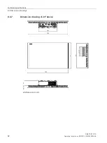
Страница 76: ...Technical specifications 8 3 Dimension drawings SIMATIC IPC277G 76 Operating Instructions 08 2021 A5E50059956 AA 8 3 Dimension drawings all dimensions in mm 8 3 1 Dimension drawing of 7 device ...

Страница 77: ...Technical specifications 8 3 Dimension drawings SIMATIC IPC277G Operating Instructions 08 2021 A5E50059956 AA 77 8 3 2 Dimension drawing of 10 device all dimensions in mm ...

Страница 78: ...Technical specifications 8 3 Dimension drawings SIMATIC IPC277G 78 Operating Instructions 08 2021 A5E50059956 AA 8 3 3 Dimension drawing of 12 device all dimensions in mm ...

Страница 79: ...Technical specifications 8 3 Dimension drawings SIMATIC IPC277G Operating Instructions 08 2021 A5E50059956 AA 79 8 3 4 Dimension drawing of 15 device all dimensions in mm ...

Страница 80: ...Technical specifications 8 3 Dimension drawings SIMATIC IPC277G 80 Operating Instructions 08 2021 A5E50059956 AA 8 3 5 Dimension drawing of 19 device all dimensions in mm ...

Страница 81: ...Technical specifications 8 3 Dimension drawings SIMATIC IPC277G Operating Instructions 08 2021 A5E50059956 AA 81 8 3 6 Dimension drawing of 22 device all dimensions in mm ...

Страница 82: ...Technical specifications 8 3 Dimension drawings SIMATIC IPC277G 82 Operating Instructions 08 2021 A5E50059956 AA 8 3 7 Dimension drawing of 24 device all dimensions in mm ...

Страница 83: ...r 30W 24VDC 19 2 to 28 8V Rated output power 80W Power consumption DC 40 60 full load 24 VDC at 85 efficiency Pout 6W 24 VDC at 70 efficiency Pout 6W 24 VDC at 50 efficiency 50 to 100 nominal output power 24VDC at 85 efficiency Current consumption Max 1 9 A at 24 V Max 5 0 A at 24 V Noise emission 55 dB A according to DIN 45635 1 Degree of protection IP20 Enclosure IP65 Front in accordance with IE...

Страница 84: ...port extension cable 30 m 2 kV 5 kHz 100 kHz in accordance with IEC 61000 4 4 Length of signal port extension cable 30 m Surge 2kV shielding to earth in accordance with IEC 61000 4 5 Length of signal port extension cable 30 m Immunity to discharges of static electricity 6 kV contact discharge in accordance with IEC 61000 4 2 8 kV air discharge in accordance with IEC 61000 4 2 Immunity to RF interf...

Страница 85: ...mory modules 4G DDR4 SDRAM 8G DDR4 SDRAM 16G DDR4 SDRAM The max speed of memory is up to 3200 MT s The memory module supports IBECC function and its default value in BIOS is Disable M 2 Module Slot X100 support NGFF M 2 2230 2242 2260 2280 3030 3042 3052 with Key B Key B M Slot X101 support NGFF M 2 2230 2242 2260 3030 3042 with Key B Key B M Max permitted totally power loss for each M 2 B key mod...

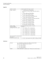
Страница 86: ...ixels Full HD 24 screen diagonal with backlighting resolution 1920 1080 pixels Full HD Touch controller Projected capacitive touch screen 5 points Backlighting MTBF Half brightness life time typical LCD s LED 7 min 50000 h at 25 C 50 brightness 10 min 50000 h at 25 C 50 brightness 12 min 70000 h at 25 C 50 brightness 15 min 50000 h at 25 C 50 brightness 19 min 50000 h at 25 C 50 brightness 22 min ...

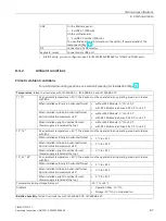
Страница 87: ...t Vertical inclination maximum 45 without M 2 Module 0 C to 50 C with M 2 Module load max 5W 0 C to 45 C When installed upright in vertical format Power supply is located at the top without M 2 Module 0 C to 50 C with M 2 Module load max 5W 0 C to 45 C 12 15 At an ambient temperature 40 C the device must be operated in an operating area in accordance with RAL When installed vertically in horizonta...

Страница 88: ... tested in accordance with IEC 61131 2 2017 Altitude Derating ratio for temperature 1 0 to 2000 2 m 1 0 3000 m 0 9 1 Equipment ambient temperature rating at 2000 m 2 Atmospheric pressure and air density increases with decreasing altitude Therefore utilization of the derating factor for 0 m to 2000 m for altitudes below sea level is considered conservative Mechanical ambient conditions Vibration re...

Страница 89: ...uce heat The device may overheat The auxiliary components will be damaged 8 4 4 Power supply 7 and 10 device Technical specifications Input voltage 24 VDC 19 2 to 28 8 VDC Power consumption 1 Max 32 W Maximum input current 1 9 A at 24 V Buffering upon power failure Hold up time 20 ms after 5 ms DC_FAIL becomes active Maximum continuous output power 1 30 W 1 The power specifications apply to the po...

Страница 90: ... up time 20 ms after 5 ms DC_FAIL becomes active Maximum continuous output power 1 80 W 1 The power specifications apply to the power supply component not to the device Note Inrush current The device needs an inrush current of at least 4 5 A for 25 ms The peak value of the inrush current depends on the input voltage and the impedance of the 24 V source peak currents in excess of 4 5 A are possible...

Страница 91: ...tom x6414RE Processor 1 5 GHz Memory DDR4 SDRAM Memory expansion up to 16 GB with the following memory modules 4G DDR4 SDRAM 8G DDR4 SDRAM 16G DDR4 SDRAM Graphics Integrated graphics Intel UHD Graphics 8 5 2 External interfaces 8 5 2 1 Overview of external interfaces Interface Position Description USB 1 External 4 USB 3 1 Gen2 up to 10Gb s Ethernet port External 3 RJ45 Ethernet 10 100 1000 Mbps Di...

Страница 92: ...channel USB3 Output 9 TX Data channel USB3 Output 8 5 2 3 DC in connector Pin Short description 1 24V 2 GND 8 5 2 4 Ethernet port Ethernet RJ45 interface Pin no Short description Meaning Input output 1 BI_DA Bi directional data A Input output 2 BI_DA Bi directional data A Input output 3 BI_DB Bi directional data B Input output 4 BI_DC Bi directional data C Input output 5 BI_DC Bi directional data ...

Страница 93: ...erface Pin no Abbreviation Meaning Input output 1 ML_Lane 0 DP data 0 Output 2 GND Ground 3 ML_Lane 0 DP data 0 Output 4 ML_Lane 1 DP data 1 Output 5 GND Ground 6 ML_Lane 1 DP data 1 Output 7 ML_Lane 2 DP data 2 Output 8 GND Ground 9 ML_Lane 2 DP data 2 Output 10 ML_Lane 3 DP data 3 Output 11 GND Ground 12 ML_Lane 3 DP data 3 Output 13 CONFIG1 CONFIG1 14 CONFIG2 CONFIG2 15 AUX_CH Auxiliary channel...

Страница 94: ...t ready I 7 RTS Request to send O 8 CTS Clear to send I 9 RI Incoming call I Pin assignment RS422 Pin Short description Meaning 1 TX Transmit data O for full duplex mode 2 TX Transmit data O for full duplex mode 3 RX Receive data I for full duplex mode 4 RX Receive data I for full duplex mode 5 M Signal ground 6 nc 7 nc 8 nc 9 nc Pin assignment RS485 Pin Short description Meaning 1 Data Transmit r...

Страница 95: ...nternal 2 M 2 B Key PCIe3 0 SIM card adapter Internal 1 SIM card adapter slot LVDS Internal 1 LVDS connector Backlight Internal 1 Backlight connector 8 5 3 2 USB 2 0 pin header Pin Signal 1 VBUS_USB1 2 VBUS_USB2 3 USB1_D 4 USB2_D 5 USB1_D 6 USB2_D 7 GND 8 GND 9 GND 10 GND 8 5 3 3 M 2 interface M 2 Module X100 Pin no Signal Signal Pin no NC 75 74 3 3V GND 73 72 3 3V GND 71 70 3 3V NC 69 68 SUSCLK R...

Страница 96: ...M DATA GND 33 32 UIM CLK PERp1 31 30 UIM RESET PERn1 29 28 NC GND 27 26 NC NC 25 24 NC NC 23 22 NC NC 21 20 NC CONNECTOR KEY B 19 18 CONNECTOR KEY B CONNECTOR KEY B 17 16 CONNECTOR KEY B CONNECTOR KEY B 15 14 CONNECTOR KEY B CONNECTOR KEY B 13 12 CONNECTOR KEY B GND 11 10 NC USB_D 9 8 W_DISABLE USB_D 7 6 WWAN_PWR_OFF_N GND 5 4 3 3V GND 3 2 3 3V NC 1 M 2 Module X101 Pin no Signal Signal Pin no NC 7...

Страница 97: ...30 NC PERn1 29 28 NC GND 27 26 NC NC 25 24 NC NC 23 22 NC NC 21 20 NC CONNECTOR KEY B 19 18 CONNECTOR KEY B CONNECTOR KEY B 17 16 CONNECTOR KEY B CONNECTOR KEY B 15 14 CONNECTOR KEY B CONNECTOR KEY B 13 12 CONNECTOR KEY B GND 11 10 NC USB_D 9 8 W_DISABLE USB_D 7 6 NC GND 5 4 3 3V GND 3 2 3 3V NC 1 8 5 3 4 LVDS interface Pin Short description Pin Short description 1 VCC 5V 2 VCC 5V 3 M 4 M 5 PWM 6 ...

Страница 98: ...8 5 4 System resources Currently allocated system resources All system resources hardware addresses memory utilization interrupt assignment DMA channels are assigned dynamically by the Windows operating system depending on the hardware equipment drivers and connected external devices You can view the current allocation of system resources or possible conflicts in the Control Panel Procedure To vie...

Страница 99: ...ng of the bits 0 Read Write Watchdog Timer I Pulse or Level mode select 0 Pulse mode 1 Level mode 1 Read Write Not used for watchdog 2 Read Write Not used for watchdog 3 Read Write Select Watchdog Timer I count mode 0 Second Mode 1 Minute Mode 4 to 7 Reserved 8 5 5 3 Watchdog counter register Bit Read Write state Meaning of the bits 0 to 7 Read Write Watch Dog Timer I Time out value Writing a non ...

Страница 100: ...itored the status two tier can be read from the battery status register Meaning of the bits Battery status register read only address 404Dh Bit Meaning 7 6 5 4 3 2 1 0 0 0 CMOS battery capacity is still sufficient 0 1 CMOS battery capacity is exhausted remaining capacity is sufficient for approx one month 1 1 CMOS battery is empty 8 5 5 6 NVRAM address register NVRAM occupies a 512 KB memory addre...

Страница 101: ...C is performed while a SIMATIC software controller is running the software CPU can malfunction resulting in communication interruptions or failures for example Other actions that put a heavy load on the PC hardware for example running hardware tests such as benchmarks can result in malfunctions of the software CPU Do not run a BIOS update or other actions that would put a heavy load on the hardwar...

Страница 102: ...lt settings with F9 Setup Defaults Or use the BIOS Setup command Load Optimal Defaults in the Exit menu 5 Make your own Setup settings based on the table you have printed out 6 Save the BIOS Setup settings with F10 Save and Exit Performing a BIOS update NOTICE Damage to the device If you switch off the device during the update the BIOS will be incomplete and corrupt This may result in malfunctions...

Страница 103: ... initialized and any error messages are output to the screen The error messages output by system BIOS are listed below For information on error messages output by the operating system or application programs refer to the corresponding manuals On screen error messages On screen error message Meaning tip Operating system not found Possible causes No operating system installed Incorrect active boot p...

Страница 104: ...siemens com simatic tech doku portal Your local representative http w3 siemens com aspa_app Training center https www sitrain learning siemens com PLG AppLang en Industry Mall https mall industry siemens com When contacting your local representative or Technical Support please have the following information at hand MLFB of the device BIOS version for industrial PC or image version of the device Ot...

Страница 105: ...Check whether the power cord has been properly connected to the monitor and to the system unit or to the grounded shockproof outlet Check whether the monitor cable has been properly connected to the system unit and to the monitor If the monitor screen still remains dark after you have performed these checks and measures contact your technical support team The mouse pointer does not appear on the s...

Страница 106: ...ection error while bridge function is enabled Right click the Windows Start menu and select Device Manager Network adapters Interl EC GbE Connection Properties Advanced Promiscuous Mode and change its value to Enabled A 3 Notes on the use of third party modules Problem Possible cause Possible remedy The device crashes during startup Redundant I O addresses Redundant hardware interrupts and or DMA ...

Страница 107: ... symbols on your device may vary in some details from the symbols shown in the following tables B 2 Safety Symbol Meaning Symbol Meaning Warning observe the supplied documentation Lock is closed Attention radio equipment Lock is open Disconnect the power plug before opening Opening for Kensington lock Attention ESD Electrostatic sensitive device Warning of hot surface B 3 Operator controls Symbol ...

Страница 108: ...d more information in the operating instructions for your device Symbol Meaning Symbol Meaning Approved for Australia and New Zealand Marking for the Eurasian Customs Union Approved for China Test mark of Factory Mutual Research CE markings for European countries Marking of Federal Communications Commission for the USA EFUP Environment Friendly Use Period marking for China Approved for Korea Test ...

Страница 109: ...ce Protective conductor terminal PS 2 keyboard interface Connection for functional earthing equipotential bonding line Multimedia Card Reader DisplayPort interface Smart Card Reader DVI D interface Line In LAN interface not approved for connecting WAN or telephone Line Out Serial port Microphone input USB port Universal Audio Jack USB 2 0 high speed port Headphone output USB 3 0 super speed port ...

Страница 110: ...ompact Disc Read Only Memory CE Communauté Européenne CF CompactFlash CMOS Complementary Metal Oxide Semiconductors COA Certificate of authentication COM Communications Port Term for the serial interface CPU Central Processing Unit CPU CSA Canadian Standards Association Canadian organization for tests and certifications according to national or binational standards CTS Clear To Send Clear to send ...

Страница 111: ...pt Request ISA Industry Standard Architecture Bus for expansion modules LAN Local Area Network Computer network that is limited to a local area LEDs Light Emitting Diode Light emitting diode LPS Limited Power Source MAC Media access control Media access control MLFB Machine readable product designation MRAM Magnetoresistive random access memory Backup memory MS Microsoft MTBF Mean Time Between Fai...

Страница 112: ...a low voltage SMART Self Monitoring Analysis and Reporting Technology Hard disk error diagnostics program SRAM Static Random Access Memory Static RAM SSD Solid State Drive TFT Thin Film Transistor TxD Transmit Data Data transfer signal UEFI Unified Extensible Firmware Interface UL Underwriters Laboratories Inc US organization for testing and certification according to national or binational standa...

Страница 113: ...oses or for the protection of vital and non replaceable data against loss when the working copy is corrupted Certain applications automatically generate backup copies of data files and manage both the current and the previous versions on the hard disk Baud Physical unit for the step speed in signal transmission Defines the number of transferred signal states per second With only two states one bau...

Страница 114: ...Controller Integrated hardware and software controllers that control the functions of certain internal or peripheral devices for example the keyboard controller Device configuration The configuration of a PC or programming device contains information on hardware and device options such as memory configuration drive types monitor network address etc The data are stored in a configuration file and e...

Страница 115: ...Energy options The energy options can be used to reduce energy consumption of the computer while keeping it ready for immediate use This can be configured in Windows by selecting Settings Control Panel Energy options Enhanced Write Filter Configurable write filter that allows you to for example boot Windows Embedded Standard from write protected media e g CD ROM set write protection for individual...

Страница 116: ...oration of a uniform saved system state when booting This minimizes write access for example to a memory card when you start up and shut down Windows Embedded Standard 7 Hub A term in network technology In a network a device joining communication lines at a central location providing a common connection to all devices on the network Hyper Threading HT technology multi threading enables the paralle...

Страница 117: ...sources Legacy Boot Device Conventional drives can be used as USB devices License key The license key represents the electronic license stamp of a license Siemens AG issues a license key for each software that is protected by a license License key USB flash drive The license key USB flash drive contains the authorizations or license keys required to enable protected SIMATIC software Low voltage di...

Страница 118: ...lly a reference to the ability of a computer to automatically configure the system for communication with peripheral devices for example monitors modems or printers The user can plug in a peripheral and play it at once without manually configuring the system A Plug Play PC requires both a BIOS that supports Plug Play and a Plug Play expansion card POST Self test performed by the BIOS after the com...

Страница 119: ...onitoring Analysis and Reporting Technology SMART or S M A R T is an industry standard integrated in storage media It makes for permanent monitoring of important parameters and early detection of imminent problems SATA Serial ATA Interface for hard disk drives and optical drives with serial data transmission rates of up to 300 Mbps SETUP BIOS Setup A program in which information about the device c...

Страница 120: ... that allows secured execution of programs and applications It is only effective when all relevant system components such as processors operating systems and applications are supported Wake on LAN Wake on Local area network This function allows the PC to be started via the LAN interface Warm restart The restart of a computer after a program was aborted The operating system is loaded and restarted ...

Страница 121: ... protection 25 88 Device Closing 54 Open 53 DiagBase software 45 DiagMonitor Temperature monitoring 45 Diagnostics 45 DiagBase software 45 Directive ESD Directive 79 Display Size 9 DisplayPort interface 97 Drive 89 E EAC 77 Earth connection 50 ESD 79 ESD Directive 79 Ethernet 41 95 Ethernet address 23 Ethernet interface 96 F FCC 76 Flexible mudule Installing 56 Front view 11 12 G General technical...

Страница 122: ... Initial commissioning 43 Operation Capacitive multi touch screen 50 Touch screen 49 P Package contents 21 Checking 21 Packaging 21 Checking 21 Removing 21 PE conductor 50 Pile au lithium 65 Processor 89 Product label 23 PROFINET 41 Protection class 88 Protective measure Static electricity 80 R Radiation 19 High frequency radiation 19 RAM 89 RCM 77 RCM Australia New Zealand 77 Repairs 61 62 S Safe...

Страница 123: ...dex SIMATIC IPC277G Operating Instructions 08 2021 A5E50059956 AA 123 U UKCAI 77 USB 95 99 USB 3 0 Interface 96 V Ventilation slits 27 W Warranty 17 Watchdog 46 Monitoring function 46 Monitoring times 46 ...

Отзывы: