3-4
C7-621 / C7-621 AS-i Control Systems
C79000-G7076-C621-01
3.2
Rules for Configuring an MPI Network
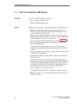
This section deals with the following topics:
S
How to configure an MPI network
S
Rules for configuring the network
Remember the following rules when connecting nodes to an MPI network:
S
Before interconnecting the individual nodes of the MPI network, you
must first assign the MPI address and the highest MPI address to each
node (except for the RS 485 repeater).
Tip: Put a label with the MPI address on the housing of all the nodes in
the MPI network. This means that you can always see which MPI address
has been assigned to which node in your system.
S
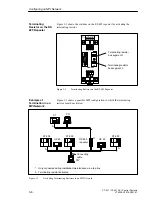
Connect up all the nodes on the MPI network as shown in Figure 3-3, in
other words integrate the stationary programming devices and OPs
directly in the MPI network.
This means that only the programming devices or OPs required for
installation or maintenance must be connected via tap lines to the MPI
network.
S
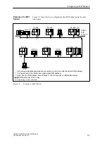
If you operate more than 32 nodes in a network, the bus segments must be
connected via RS 485 repeaters.
S
Ungrounded bus segments and grounded bus segments are connected via
RS 485 repeaters.
S
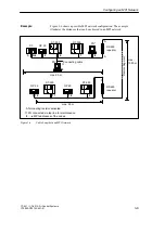
Each RS 485 repeater in the network reduces the maximum number of
nodes per bus segment. This means that if there is an RS 485 repeater in a
bus segment, the maximum number of other nodes is reduced to 31 for
this segment. The number of RS 485 repeaters in the network, however,
does not affect the maximum number of nodes on the network.
Up to 10 segments can be connected in series.
S
Activate the terminating resistor on the first and last node in a segment.
S
Before you include a new node in the MPI network, you must first turn
off its power supply.
Overview
Rules
Configuring an MPI Network
Содержание simatic c7-621
Страница 44: ...2 26 C7 621 C7 621 AS i Control Systems C79000 G7076 C621 01 Installing and Preparing the C7 ...
Страница 64: ...3 20 C7 621 C7 621 AS i Control Systems C79000 G7076 C621 01 Configuring an MPI Network ...
Страница 74: ...5 4 C7 621 C7 621 AS i Control Systems C79000 G7076 C621 01 Attaching a C7 621 AS i ...
Страница 82: ...6 8 C7 621 C7 621 AS i Control Systems C79000 G7076 C621 01 C7 621 Digital I Os ...
Страница 100: ...7 18 C7 621 C7 621 AS i Control Systems C79000 G7076 C621 01 C7 621 Analog I Os ...
Страница 101: ...8 1 C7 621 C7 621 AS i Control Systems C79000 G7076 C621 01 Maintenance 8 ...
Страница 110: ...A 8 C7 621 C7 621 AS i Control Systems C79000 G7076 C621 01 General Technical Specifications ...
Страница 123: ...Glossary 1 C7 621 C7 621 AS i Control Systems C79000 G7076 C621 01 Glossary ...
Страница 136: ...Index 4 C7 621 C7 621 AS i Control Systems C79000 G7076 C621 01 Index ...

