


Controller
6.6 Connecting terminals and interfaces
ATE500E
System Manual, 09/2017, A5E33917696-AD
71
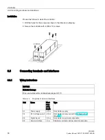
6.6.5
CAN module
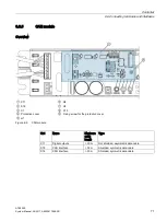
Overview
①
X11
⑥
H2
②
X16
⑦
H3
③
S1
⑧
X15
④
Protective cover
⑨
Fixing screw for the protective cover
⑤
H1
Figure 6-6
CAN module
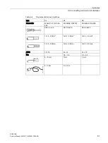
Slot
Name
Maximum
cable
length
Type
X11
Digital outputs
> 30 m
Not shielded, asymmetric data cable
X15
CAN interface
> 30 m
Shielded, symmetric data cable
X16
CAN interface
> 30 m
Shielded, symmetric data cable
Содержание SIDOOR ATE500E
Страница 1: ......
Страница 53: ...Controller 6 4 Operation and parameter assignment ATE500E System Manual 09 2017 A5E33917696 AD 53 ...
Страница 54: ...Controller 6 4 Operation and parameter assignment ATE500E 54 System Manual 09 2017 A5E33917696 AD ...
Страница 56: ...Controller 6 4 Operation and parameter assignment ATE500E 56 System Manual 09 2017 A5E33917696 AD ...
Страница 57: ...Controller 6 4 Operation and parameter assignment ATE500E System Manual 09 2017 A5E33917696 AD 57 ...
Страница 58: ...Controller 6 4 Operation and parameter assignment ATE500E 58 System Manual 09 2017 A5E33917696 AD ...
Страница 95: ...Motor 7 2 Installation ATE500E System Manual 09 2017 A5E33917696 AD 95 ...


