SIDOOR functions
3.2 System functions
ATD4xxW Door Controller for Industrial Applications
System Manual, 01/2017, A5E38080677-AB
55
3.2.6
Friction compensation
Description of function
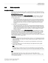
The friction force profile of the door system is recorded with the current measuring device of
the controller. The measurement data for both the opening and closing directions is recorded
during the learn run.
Recording of measurement data
The recording of measurement data in the opening direction is divided into two subranges
because the door movement is not constant throughout the total range. The ranges are:
●
Travel path ≤ 25
cm
–
The measurement data in this range are recorded in the second opening movement
and after reaching the speed trigger level (learn run speed). As from this moment, the
door movement is almost constant. The measurement data are recorded every 2 cm,
the first measured value is recorded 2 cm after the trigger level position (transient
distance).
●
Travel path > "End of weight determination"
–
The measurement data in this range are recorded after the weight determination has
finished and the speed trigger level has been reached (learn run speed). As from this
moment, the door movement is almost constant. The measurement data are recorded
every 2 cm, the first measured value is recorded 2 cm after the trigger level position
(transient distance).
The measurement data are recorded in the closing direction throughout the entire closing
movement within the learn run and after reaching the speed trigger level (learn run speed).
As from this moment, the door movement is almost constant. The measurement data are
recorded every 2 cm, the first measured value is recorded 2 cm after the trigger level
position (transient distance). The measured values are recorded until the system reaches the
"Cutter distance CLOSE" range (p3663).
Calculations
1.
The values "MEAN FRICTION FORCE OPEN/CLOSE [A]" and "STANDARD DEVIATION
OPEN/CLOSE [A]" in the "open" and "closed" positions are calculated on the basis of the
measurement data.
2.
The values calculated in step 1 are converted to a force [N] with the aid of the motor
constants [N/A]
3.
The force calculated in step 2 is added internally to the parameterized forces p3682,
p3683, p3684, and p3685
Note
The friction force is not taken into account in the parameterized torques p3679, p3680
and p3681 (effective in the end stops) in order to avoid unnecessary heating of the motor.
Note
The corresponding internal force value, which is the result of the addition of the
parameterized force value and the calculated friction force, is limited to the maximum value
of the respective parameter.


