Siemens SCD 1297-K (33) Скачать руководство пользователя страница 50

Operating instruction 


Control panel SCD 1297-K


Page  50 / 64 

DOC-Nr.: b40008de3.doc


Operation and Alignment 

This chapter contains a description of the operating and alignment functions. 


3.1 

Location of the Operation and Alignment Control 

The operating controls such as the keyboard and mouse are accessible from the front of the 
unit. Buttons for aligning the display are located on the rear of the unit. The location of the 4 
keys for the OSD can be seen in Fig. 1, page 42. The display can also be aligned using an 
externally connected PS2 keyboard. 


3.2 

Integrated Foil keyboard 

The integrated foil keyboard has 94 keys which can each be defined separately. The keys 
can be separated into two groups. One group consists of the so-called soft keys, which are 
located to the left of, to the right and above the display. These keys can be labeled with the 
help of a slide in strip. The second group of keys is already labeled. 

The soft keys and the HELP, SHIFT and ACK keys also have an LED each which can be 
switched on and off via the keyboard interface. 


3.2.1 

Programming the Keys 

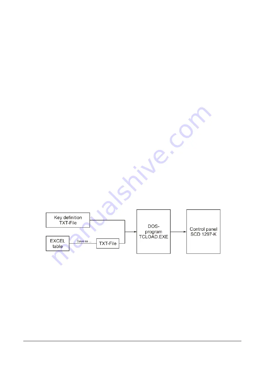
All the keys in the integrated foil keyboard can be freely programmed. A small DOS program, 
“TCLOAD.EXE” is used to program the keys via the keyboard interface. The keys are defined 
in an editable list or an Excel table. This is read and interpreted by the DOS program, which 
then sends these definitions to the control panel. 


Important: 

The TCLOAD.EXE program can only read and process text files. Therefore, in Excel, it is 
necessary to save the table using “Save as...” and to select the file type “Formatted text 
(space delimited)”. 


Содержание SCD 1297-K (33)

Страница 1: ...etriebsanleitung Bedienpanel SCD 1297 K Seite 1 64 DOC Nr b40008de3 doc Hochauflösender 31 cm 12 LCD Bedienpanel SCD 1297 K Betriebsanleitung SCD 1297 K 33 Rack 19 6AV8100 0BC00 0AA0 Copyright Siemens AG ...

Страница 2: ...008de3 doc Weitergabe sowie Vervielfältigung dieser Unterlagen Verwertung und Mitteilung ihres Inhaltes sind nicht gestattet soweit nicht ausdrücklich zugestanden Zuwiderhandlungen verpflichten zu Schadenersatz Alle Rechte vorbehalten 2006 Alle Rechte vorbehalten ...

Страница 3: ...DC 15 2 3 8 2 Spannungsversorgung 24 VDC 16 2 4 Verbindung mit dem Rechnersystem 16 2 5 Elektrische Inbetriebnahme 17 2 6 Inbetriebnahme der Tastatur Maus 17 3 Bedienung und Abgleich 18 3 1 Lage der Bedien und Abgleichelemente 18 3 2 Integrierte Folientastatur 18 3 2 1 Programmierung der Tasten 18 3 2 1 1 Aufbau der Tastenzuordnungstabelle 19 3 2 1 2 Schlüsselwörter bzw Zeichen 19 3 2 1 3 Syntax e...

Страница 4: ...10 Abb 2 Schalttafelausschnitt 10 Abb 3 Lage der Schnittstellen 11 Abb 4 Verbindung des SCD 1297 K mit dem Rechnersystem bei geringen Distanzen 16 Abb 5 Verbindung des SCD 1297 K mit dem Rechnersystem bei großen Distanzen 17 Abb 6 Tastenzuordnungstabelle 19 Abb 7 Tastaturmatrix 31 Abb 8 Zuordnung MF2 Tastennummern 32 ...

Страница 5: ... LCD Anzeige in diesem Bedienpanel werden Verzerrungen der Bildgeometrie und Farbflecken vermieden Der SCD 1297 K liefert selbst bei niedrigen Bildwechselfrequenzen von 50 Hz noch flimmerfreie Bilder Kleinere und größere Bildauflösungen werden formatfüllend auf dem Display dargestellt Der SCD 1297 K kann bis zu 256K 16 7 Mio durch Interpolation Farben gleichzeitig darstellen Somit können Echtfarbb...

Страница 6: ...nsatzbereich und Besonderheiten des Gerätes hingewiesen Kapitel 2 Inbetriebnahme Hier geht es im Wesentlichen um vorbereitende Arbeiten wie dem Einbau bzw die Aufstellung des Gerätes und seine Verkabelung bzw die Verbindung mit einem Rechnersystem Kapitel 3 Bedienung Dieses Kapitel beschreibt alle Bedien und Abgleichelemente des SCD 1297 K Weiterhin wird in diesem Kapitel beschrieben wie die Folie...

Страница 7: ...ezüglich Emission und Immission des Bereiches Industrie ein Reparaturen Vor dem Öffnen des Gerätes ist die Versorgungsspannung abzuschalten Das Öffnen ist nur von autorisiertem Fachpersonal durchzuführen Erweiterungen oder Änderungen des Gerätes können das System beschädigen oder das EMV Verhalten beeinträchtigen Reinigung Vor der Reinigung ist das Gerät vom Netz zu trennen Bei stärkerer Verschmut...

Страница 8: ... nur Service Personal sollten Sie folgende Hinweise befolgen Wenn elektronische Baugruppen gehandhabt werden ist für eine statische Entladung zu sorgen Dieses kann zum Beispiel durch das Berühren von g Gleiches gilt natürlich für zu benutzendes schutzisoliertes Werkzeug Dieses muss ebenfalls an einem geerdeten Gegenstand entladen werden Wenn Baugruppen aus dem System entfernt oder hinzugefügt werd...

Страница 9: ...orgung Einbau in Ihr System unter Berücksichtigung technischer und ergonomischer Gesichtspunkte 2 1 Auspacken und Überprüfen der Einzelteile Nach dem Auspacken aller gelieferten Komponenten sind diese auf Vollständigkeit und Transportschäden Sichtkontrolle zu überprüfen Sollten hierbei Mängel festgestellt werden benachrichtigen Sie bitte die im Lieferschein ausgewiesene Serviceabteilung Sie sollte...

Страница 10: ... Seite 10 64 DOC Nr b40008de3 doc 2 2 Installation Einbau des Monitors Der SCD 1297 K wird als Standard 19 Einschub in einen 19 Schrank montiert Trageschienen sind nicht erforderlich Abb 1 Abmessung des SCD 1297 K Abb 2 Schalttafelausschnitt ...

Страница 11: ...nitors führen kann EMV Problematik Das vorliegende Gerät dient als Einbaukomponente in einer industriellen Anwendung Der Betreiber der Gesamtanlage ist zur Einhaltung der elektromagnetischen Verträglichkeit nach dem EMV Gesetz angehalten Sicherheitsproblematik Alle Spannungs und Signalanschlüsse sind nach den gültigen Rechtsvorschriften auszuführen Ergonomie Der Bildschirm sollte von allen Seiten ...

Страница 12: ...gen DVI Stecker realisiert Pin Signal 1 TMDS Data 2 2 TMDS Data 2 3 TMDS Data Shield 2 GND 4 5 6 DDC CLK 7 DDC DATA 8 Analogue V Sync 9 TMDS Data 1 10 TMDS Data 1 11 TMDS Data Shield 1 GND 12 13 14 5 V Power In 15 GND 16 Hot Plug Detect 17 TMDS Data 0 18 TMDS Data 0 19 TMDS Data Shield 0 GND 20 21 22 TMDS CLK Shield GND 23 TMDS CLK 24 TMDS CLK ...

Страница 13: ...deo Eingang Rot 2 Video Eingang Grün 3 Video Eingang Blau 4 Frei 5 Frei 6 GND Rot 7 GND Grün 8 GND Blau 9 frei 10 GND 11 frei 12 frei 13 H Sync 14 V Sync 15 frei 2 3 3 Externe Tastatur X3 Rückseitig kann eine Standard PS2 Tastatur angeschlossen werden Diese Tastatur kann parallel mit der frontseitigen Tastatur bedient werden Pin Signal 1 Data 2 3 GND 4 5V 5 CLK 6 15 14 13 12 11 10 9 8 7 6 5 4 3 2 ...

Страница 14: ...nersystem kann ein Standard PS2 Kabel Stecker Stecker mit einer Länge von maximal 5 m verwendet werden Pin Signal 1 Data 2 3 GND 4 5V 5 CLK 6 2 3 5 PC Schnittstelle Maus X5 Diese Schnittstelle stellt die Mausverbindung mit dem Rechnersystem her und ist als Standard PS2 buchse ausgeführt Zur Verbindung mit dem Rechnersystem kann ein Standard PS2 Kabel Stecker Stecker mit einer Länge von maximal 5 m...

Страница 15: ...muss auf der PC Seite ein entsprechender Empfänger verwendet werden der diese Signale wieder in die PC üblichen Signale für Tastatur und Maus umwandelt siehe auf Seite 17 Pin Signal 1 KBD DATA 2 KBD DATA 3 MOUSE DATA 4 KBD CLK 5 KBD CLK 6 MOUSE DATA 7 MOUSE CLK 8 MOUSE CLK 2 3 7 Servicebuchse X6 Diese Servicebuchse dient zum nachträglichen Laden einer neuen Betriebssoftware in das SCD 1297 K 2 3 8...

Страница 16: ... vorgesehenen Stecker durchzuführen Die Anschlüsse des Monitors sind EMV gerecht auszuführen Die Verbindung zum Rechnersystem kann auf zwei verschiedenen Arten erfolgen Ist die Leitungslänge zwischen SCD 1297 K und dem Rechnersystem 5 m können die Standard PS2 Verbindungen verwendet werden Jedoch sollte berücksichtigt werden dass diese Schnittstellen nicht für ein industrielles Umfeld ausgelegt si...

Страница 17: ...tecker der Schnittstellen korrekt angesteckt und verschraubt sind Wenn ein VGA Signal am Bedienpanel anliegt wird das Bild direkt auf dem Schirm dargestellt 2 6 Inbetriebnahme der Tastatur Maus In der Regel werden während des Startvorgangs eines Rechnersystem Tastatur und Maus überprüft und initialisiert Fehlen diese Eingabegeräte kann der Rechner den Startvorgang anhalten oder das Eingabegerät is...

Страница 18: ...oftkeys die links rechts und unterhalb des Displays angeordnet sind Diese Tasten können mit Hilfe von Einsteckstreifen beschriftet werden Die fest beschrifteten Tasten bilden die zweite Gruppe Die Softkeys und die Tasten HELP SHIFT und ACK sind zusätzlich mit einer LED ausgestattet Die LED s können über die Tastaturschnittstelle angesteuert werden 3 2 1 Programmierung der Tasten Alle Tasten der in...

Страница 19: ...esteht aus einem Tabellenkopf in dem der Benutzer diverse Informationen als Kommentar hinterlegen kann die Tastenzuordnungstabelle der ersten Tastenebene und der Tastenzuordnungstabelle der zweiten Ebene Zwischen den Tabellen der beiden Ebenen wird noch definiert welche der Tasten als Umschalttaste zwischen den Ebenen dient 3 2 1 2 Schlüsselwörter bzw Zeichen Name Hier kann der Tabelle ein Name ge...

Страница 20: ...äquivalenten MF2 Taste In der Abb 8 auf Seite 32 im Anhang werden die Tastennummer einer Standard MF2 Tastatur dargestellt Zwischen Rechner und Tastatur werden immer nur Tastennummern ausgetauscht Die Belegung der Taste selbst d h ob auf dem Bildschirm nun ein Z oder Y erscheint wird durch Tabellen Tastaturtreiber im Rechner selbst festgelegt Flags Die Flags legen bestimmte Verhaltensweisen bzw we...

Страница 21: ...D s anzusteuern wurde ein Sonderkommando implementiert Mit diesem Kommando können die einzelnen LED s ein und ausgeschaltet werden Die Zuordnung der LED Nummern zu der LED Position ist in der Abb 7 auf Seite 31 Das Sonderkommando für die LED Daten lautet OxEA gefolgt von 10 Bytes mit den LED Informationen Aufbau des Protokolls 0xEA B1H B1L B2H B2L B3H B3L B4H B4L B5H B5L 0xEA Sonderkommando B1 B5 ...

Страница 22: ...5 0 B4 5 LED11 S11 0 B2 2 LED30 F14 1 B4 6 LED10 S10 X 1 B2 3 LED29 F13 1 B2L D 0x44 B4 7 LED9 S9 X 1 B4H D 0x44 B2 4 LED28 F12 0 B5 0 LED8 S8 0 B2 5 LED27 F11 0 B5 1 LED7 S7 0 B2 6 LED26 F10 X 1 B5 2 LED6 S6 0 B2 7 LED25 F9 0 B2H 4 0x34 B5 3 LED5 S5 X 1 B5L 8 0x38 B3 0 LED24 F8 0 B5 4 LED4 S4 X 1 B3 1 LED23 F7 X 1 B5 5 LED3 S3 X 1 B3 2 LED22 F6 X 1 B5 6 LED2 S2 X 1 B3 3 LED21 F5 X 1 B3L E 0x45 B5...

Страница 23: ...nt ist die Bedienung des OSD s auch über eine angesteckte MF2 Tastatur möglich Die OSD Steuerung wird mit den Cursor Tasten bedient Um das OSD über die externe Tastatur zu aktivieren sind die Tasten CTRL ALT und M gleichzeitig zu drücken Wird innerhalb von 10 Sekunden keine weitere Taste gedrückt schaltet der Monitor wieder in den normalen Tastaturmodus zurück Das OSD selbst verschwindet auch nach...

Страница 24: ...haften Folgende Einstellungen können über das Quick OSD Menü aufgerufen werden Aufruf durch die Taste SET bzw MF Cursor Up Down Funktion Einstellen Einstellwert Beschreibung Einstellbereich 0 bis 100 über Einstelltasten Kontrast einstellen Anpassen der Wiedergabe der hellen Bildpartien Einstellbereich 0 bis 100 über Einstelltasten Helligkeit einstellen Anpassen der Wiedergabe der dunklen Bildparti...

Страница 25: ...aste MF2 Funktion en Cursor rechts Einstellparameterwert erhöhen Auswahl nach rechts Cursor links Einstellparameterwert erniedrigen Auswahl nach links Ein Ausschalten MENU Enter OSD Aufruf Hauptmenü Untermenü auswählen SET Cursor Up Down Punkte im Hauptmenü Untermenü von oben nach unten durchgehen auswählen Aufruf durch die Taste MEN bzw MF Enter ...

Страница 26: ...ünschte Farbtemperatur bzw Farbton einstellen Drei festdefinierte und eine einstellbare Farbtemperatur stehen zur Auswahl Wird VAR aktiviert erscheinen für RGB jeweils ein Einstellbalken Einstellbereich 0 bis 100 50 entspricht Faktor 1 Optionen 1 OSD Auswahl zwischen neun festdefinierten OSD Positionen Position OSD definieren OSD H Position Einstellbereich 0 bis 100 über Einstelltasten OSD Menü in...

Страница 27: ...gen in den Synchronisationssignalen Es verhindert einen erneuten Bildabgleich während der Darstellung eines Video signals bei kurzzeitigen Störungen auf den Synchronisationssignalen RGB Signal 1 verriegeln EIN Taste Standardeinstellung AUS Bei EIN Das gerade dargestellte Videotiming wird gespeichert und mit einer höheren Toleranz in H und V Frequenz verarbeitet D h die Einstellungen dieses Timings...

Страница 28: ...letten automatischem Abgleich ohne den automatischen Frequenz Abgleich H sichtbar 100 bis 2000 über Einstelltasten Horizontale Bildauflösung einstellen wichtigster Parameter V sichtbar 100 bis 2000 über Einstelltasten Vertikale Bildauflösung einstellen wichtigster Parameter H total 100 bis 2500 über Einstelltasten Anzahl der gesamten Pixel in einer Zeile einstellen wichtigster Parameter H Start 0 ...

Страница 29: ...CFT Cold Cathode Fluorescent Tube Helligkeit typisch ca 370 cd m Kontrast 450 1 Blickwinkel typisch L R O U 70 50 60 4 2 Stromversorgung Eingangsspannung Limited power source max 8A 11 4 12 6 VDC 18 36 VDC 100 240 VAC Leistungsaufnahme Normalbetrieb ca 25 W Leistungsaufnahme StandBy ca 5 W 4 3 Betriebsbedingungen Betriebstemperatur 0 bis 45 C Lagertemperatur 25 bis 60 C Feuchtigkeit Max 95 keine K...

Страница 30: ...mposite Sync H Frequenz 30 bis 97 kHz V Frequenz 50 bis 100 Hz 4 7 EU Konformitätserklärung über EMV Produkt LCD Monitor SCD 1297 K Prüfgrundlagen EG Rahmenrichtlinien No 89 336 EWG No 73 23 EWG Angewandte Harmonisierte Normen EN 50081 2 EN55022 Class A Emissions EN61000 6 2 EN610003 2 EN610003 3 Immission EN 60950 Sicherheit Das Gerät erfüllt zusätzlich die Anforderungen der FCC Class A 4 8 Weite...

Страница 31: ...Betriebsanleitung Bedienpanel SCD 1297 K Seite 31 64 DOC Nr b40008de3 doc SIEM ENS 5 Anhang Abb 7 Tastaturmatrix ...

Страница 32: ...C V B N M µ Strg Alt Alt Gr Strg Einfg Pos1 Pos1 Bild Bild Bild Bild Entf Ende Ende Num 7 8 9 4 5 6 1 2 3 0 Einfg Entf Enter 110 112 113 114 115 116 117 118 119 120 121 122 123 124 125 126 1 2 3 4 5 6 7 8 9 10 11 12 13 15 16 17 18 19 20 21 22 23 24 25 26 27 28 30 31 32 33 34 35 36 37 38 39 40 41 42 43 44 45 46 47 48 49 50 51 52 53 54 55 57 58 60 61 62 64 75 80 85 76 81 86 83 79 84 89 90 95 100 105...

Страница 33: ... instruction Control panel SCD 1297 K Page 33 64 DOC Nr b40008de3 doc High Resolution 31 cm 12 LCD Control Panel SCD 1297 K 33 Operating Instruction SCD 1297 K 33 Rack 19 6AV8100 0BC00 0AA0 Copyright Siemens AG ...

Страница 34: ...Control panel SCD 1297 K Page 34 64 DOC Nr b40008de3 doc No part of this document may be reproduced or transmitted without express permission Violations will result in prosecution All Rights reserved 2006 All Rights reserved ...

Страница 35: ...r supply 12 VDC 47 2 3 8 2 Power supply 24 VDC 48 2 4 Connecting to the Computer System 48 2 5 Electrical Installation 49 2 6 Installing the Keyboard and Mouse 49 3 Operation and Alignment 50 3 1 Location of the Operation and Alignment Control 50 3 2 Integrated Foil keyboard 50 3 2 1 Programming the Keys 50 3 2 1 1 Key Definition Table 51 3 2 1 2 Keywords characters 51 3 2 1 3 Syntax of a table en...

Страница 36: ...g 2 Cut out control panel 42 Fig 3 Location of the interfaces and alignment controls 43 Fig 4 Connecting the SCD 1297 K to the computer system over a short distance 48 Fig 5 Connecting the SCD 1297 K to the computer system over a longer distance 49 Fig 6 Key definition table 51 Fig 7 Keyboard matrix 63 Fig 8 MF2 key numbers 64 ...

Страница 37: ... TFT LCD display in this control panel minimizes picture geometry distortion and color patches The screen remains flicker free even at the low refresh rate of 50 Hz Images of higher or lower resolution than that of the screen will be contracted or expanded to fit on the display The SCD 1297 K can display up to 256k 16 7 million using interpolation colors simultaneously allowing true color images a...

Страница 38: ...tion of the SCD 1297 K including its properties application areas and special features Chapter 2 Installation This chapter is mainly concerned with preparing the LCD monitor for use its installation and cabling Chapter 3 Operation All operations and adjustment possibilities for the SCD 1297 K are described here Chapter 4 Technical Data This chapter contains technical details such as dimensions pow...

Страница 39: ...ng into industrial systems The operator of the entire plant is responsible for maintaining electromagnetic compatibility according to EMC law Repairs Before the unit is opened the supply voltage must be switched off Only authorized persons may open the unit Additions or changes to the unit may damage the system or affect its EMC behavior Cleaning The unit must be isolated from the power supply bef...

Страница 40: ...d service technician are handling such assemblies then the following precautions should be observed When such assemblies are being handled a means of electrostatic discharge must be available This can be for example a grounded object which can be touched to discharge electrostatic voltages This applies to all insulated used tools They must also be discharged at grounded object When assemblies are ...

Страница 41: ...and power supply Building into your system bearing in mind technical and ergonomic aspects 2 1 Removing the packaging and checking individual parts After unpacking all the delivered components they should be checked for completeness and for possible transport damage visual inspection If any deficiencies are found then please contact the service department given on the delivery note Have the delive...

Страница 42: ...D 1297 K Page 42 64 DOC Nr b40008de3 doc 2 2 Installation of the monitor The SCD 1297 K is a 19 rack module and is mounted in a standard 19 cabinet Guide rails are not necessary Fig 1 Dimensions of the SCD 1297 K Fig 2 Cut out control panel ...

Страница 43: ... to a significant reduction in the lifetime of the monitor EMC Problems This unit has been designed for building into an industrial system The operator of the entire plant is responsible for maintaining electromagnetic compatibility according to EMC laws Safety Problems All voltage and signal connections must adhere to legal requirements Ergonomics The screen should be easily viewable from all sid...

Страница 44: ... DVI connector Pin Signal 1 TMDS Data 2 2 TMDS Data 2 3 TMDS Data Shield 2 GND 4 5 6 DDC CLK 7 DDC DATA 8 Analogue V Sync 9 TMDS Data 1 10 TMDS Data 1 11 TMDS Data Shield 1 GND 12 13 14 5 V Power In 15 GND 16 Hot Plug Detect 17 TMDS Data 0 18 TMDS Data 0 19 TMDS Data Shield 0 GND 20 21 22 TMDS CLK Shield GND 23 TMDS CLK 24 TMDS CLK ...

Страница 45: ...ED 2 Video Input GREEN 3 Video Input BLUE 4 NC 5 NC 6 GND RED 7 GND GREEN 8 GND BLUE 9 NC 10 GND 11 NC 12 NC 13 H Sync 14 V Sync 15 NC 2 3 3 External keyboard X3 A standard PS2 keyboard can be connected at the rear of the unit This keyboard will then work in parallel with the built in keyboard on the front of the unit Pin Signal 1 Data 2 3 GND 4 5V 5 CLK 6 15 14 13 12 11 10 9 8 7 6 5 4 3 2 1 ...

Страница 46: ... cable male male with a maximum length of 5m should be used to connect the unit with the computer system Pin Signal 1 Data 2 3 GND 4 5V 5 CLK 6 2 3 5 PC interface mouse X5 This interface provides the mouse connection to the computer system and is a standard PS2 female connector A standard PS2 cable male male with a maximum length of 5m should be used to connect the unit with the computer system Pi...

Страница 47: ...ace is used the PC must have a corresponding receiver which can convert the incoming signals back to standard keyboard and mouse signals see Fig 5 page 49 Pin Signal 1 KBD DATA 2 KBD DATA 3 MOUSE DATA 4 KBD CLK 5 KBD CLK 6 MOUSE DATA 7 MOUSE CLK 8 MOUSE CLK 2 3 7 Service connector X6 This female connector is used for updating the SCD 1297 K software 2 3 8 Power supply It is also possible to use fo...

Страница 48: ...supply mouse keyboard and video VGA to the connectors provided These connections must adhere to EMC regulations There are two possible ways of connecting to the computer system If the cable between the SCD 1297 K and the computer system is less than 5m long then standard PS2 cables can be used However it should be noted that these interfaces have not been designed for industrial environments Exter...

Страница 49: ... secured If a VGA signal is present a picture should appear immediately on the display 2 6 Installing the Keyboard and Mouse When a computer starts up it usually checks and initializes the keyboard and mouse If either is not connected or is connected incorrectly the computer s start up procedure may stop or else the input device may not be available after it has been subsequently connected This is...

Страница 50: ...ps One group consists of the so called soft keys which are located to the left of to the right and above the display These keys can be labeled with the help of a slide in strip The second group of keys is already labeled The soft keys and the HELP SHIFT and ACK keys also have an LED each which can be switched on and off via the keyboard interface 3 2 1 Programming the Keys All the keys in the inte...

Страница 51: ...Delete Fig 6 Key definition table The table consists of a header in which the user can enter information as comments the key definition table for the first key level and the key definition table for the second key level The key which will be used to switch between the two levels is defined between the tables for the two key levels 3 2 1 2 Keywords characters Name The table can be given a name here...

Страница 52: ...s to the equivalent MF2 key Fig 8 page 64 in the appendix shows the key numbers for a standard MF2 keyboard Only key numbers are exchanged between a computer and a keyboard The definition of a key i e whether a Z or a Y appears on the screen is determined by tables keyboard drivers stored in the computer Flags The flags define specific behavior e g which control key should also be activated when t...

Страница 53: ...nce in the MF2 specification there are only NumLock CapsLock and ScrollLock LEDs This command enables the individual LEDs to be switched on and off The correlation between LED number and LED position is shown in Fig 7 page 63 The special command for the LED data is 0xEA followed by 10 Bytes with LED Information Protocol 0xEA B1H B1L B2H B2L B3H B3L B4H B4L B5H B5L 0xEA Special command B1 B5 LED in...

Страница 54: ... 4 LED12 S12 X 1 B2 1 LED31 F15 0 B4 5 LED11 S11 0 B2 2 LED30 F14 1 B4 6 LED10 S10 X 1 B2 3 LED29 F13 1 B2L D 0x44 B4 7 LED9 S9 X 1 B4H D 0x44 B2 4 LED28 F12 0 B5 0 LED8 S8 0 B2 5 LED27 F11 0 B5 1 LED7 S7 0 B2 6 LED26 F10 X 1 B5 2 LED6 S6 0 B2 7 LED25 F9 0 B2H 4 0x34 B5 3 LED5 S5 X 1 B5L 8 0x38 B3 0 LED24 F8 0 B5 4 LED4 S4 X 1 B3 1 LED23 F7 X 1 B5 5 LED3 S3 X 1 B3 2 LED22 F6 X 1 B5 6 LED2 S2 X 1 B...

Страница 55: ...ernal keyboard As already mentioned the OSD can be operated from an external MF2 keyboard The cursor keys are used to navigate in the OSD see OSD Menu page 56 and 57 In order to activate the OSD via an external keyboard the keys CRTL ALT and M should be pressed simultaneously If no other keys are pressed within 10 seconds then the display switches back to the normal keyboard mode The OSD also disa...

Страница 56: ...ghtness Zoom and picture in picture characteristics Following adjustments can do via the Quick OSD menu Invoke via key SET or MF Cursor Up Down Function Adjustment value Description Range 0 to 100 via key contrast adjustment Match the display of the bright picture parts Range 0 to 100 via key brightness adjustment Match the display of the dark picture parts Invoke via key or MF Cursor Up Function ...

Страница 57: ... s of the control keys Key MF2 Function Cursor right Increase the parameter value Go to the right Cursor left Decrease the parameter value Go to the left MENU Enter Start OSD Select the main menu submenu SET Cursor Up Down Scroll down or select menu idem in main menu submenu Invoke via key MEN or MF Enter ...

Страница 58: ...0 VAR color temperature adjust color three defined and one adjustable color temperatures are for selection Activate VAR for RGB shows up an adjustment beam 0 to 100 50 correspond to factor 1 Option 1 OSD select between nine defined OSD positions f define position OSD OSD H Position setting range 0 to 100 through key move OSD menu in horizontal position OSD V Position setting range 0 to 100 through...

Страница 59: ...on of function for noise suppression in synchronization signals Inhibits new auto alignment during display of a video signal when short term noise is present on synchronous signals Lock RGB Signal 1 ON Key Standard setting OFF At ON The video timing currently shown will be stored and processed with higher tolerance in H and V frequency I e the settings of this timing will always be used even if va...

Страница 60: ... timing parameter and perform an auto adjustment without an automatic frequency adjustment H resolution 100 to 2000 through key Horizontal image resolution important parameter V resolution 100 to 2000 through key Vertical image resolution important parameter H total 100 to 2500 through key Whole pixel per line important parameter H Start 0 to 750 through key Number of Pixels from H sync start to i...

Страница 61: ...T Cold Cathode Fluorescent Tube Brightness typical approx 370 cd m Contrast 450 1 Viewing angle typical L R T B 70 50 60 4 2 Power supply Input voltage Limited power source max 8A 11 4 12 6 VDC 18 36 VDC 100 240 VAC Power consumption normal operation approx 25 W Power consumption Standby approx 5 W 4 3 Operating Condition Operating temperature 0 to 45 C Storage temperature 25 to 60 C Relative humi...

Страница 62: ... to 97 kHz V Frequency 50 to 100 Hz 4 7 EU Declaration of Conformity on EMC Product LCD Monitor SCD 1297 K Test foundation EU framework guidelines No 89 336 EWG No 73 23 EWG Harmonized standards used EN 50081 2 EN55022 Class A Interference emissions EN61000 6 2 EN610003 2 EN610003 3 Interference resistance EN 60950 Edition 11 1997 Safety This piece of equipment also fulfils the requirements of FCC...

Страница 63: ...Operating instruction Control panel SCD 1297 K Page 63 64 DOC Nr b40008de3 doc SIEM ENS 5 Appendix Fig 7 Keyboard matrix ...

Страница 64: ...B N M µ Strg Alt Alt Gr Strg Einfg Pos1 Pos1 Bild Bild Bild Bild Entf Ende Ende Num 7 8 9 4 5 6 1 2 3 0 Einfg Entf Enter 110 112 113 114 115 116 117 118 119 120 121 122 123 124 125 126 1 2 3 4 5 6 7 8 9 10 11 12 13 15 16 17 18 19 20 21 22 23 24 25 26 27 28 30 31 32 33 34 35 36 37 38 39 40 41 42 43 44 45 46 47 48 49 50 51 52 53 54 55 57 58 60 61 62 64 75 80 85 76 81 86 83 79 84 89 90 95 100 105 91 ...

Отзывы: