background image

RUGGEDCOM RS940G

Installation Guide

4/2014

Preface

Introduction

1

Installing the Device

2

Communication Ports

3

Technical Specifications

4

Dimension Drawings

5

Certification

6

RC1036-EN-03

Содержание RUGGEDCOM RS940G

Страница 1: ...RUGGEDCOM RS940G Installation Guide 4 2014 Preface Introduction 1 Installing the Device 2 Communication Ports 3 Technical Specifications 4 Dimension Drawings 5 Certification 6 RC1036 EN 03 ...

Страница 2: ...urity concept With this in mind Siemens products and solutions undergo continuous development Siemens recommends strongly that you regularly check for product updates For the secure operation of Siemens products and solutions it is necessary to take suitable preventive action e g cell protection concept and integrate each component into a holistic state of the art industrial security concept Third...

Страница 3: ...6 2 1 2 Mounting the Device to a Panel 6 2 2 Connecting Power 7 2 2 1 Connecting High AC DC Power 8 2 2 2 Connecting Low DC Power 9 2 3 Connecting the Failsafe Alarm Relay 11 2 4 Connecting to the Device 11 2 5 Cabling Recommendations 12 2 5 1 Protection On Twisted Pair Data Ports 12 2 5 2 Gigabit Ethernet 1000Base TX Cabling Recommendations 13 Chapter 3 Communication Ports 15 3 1 Copper Ethernet ...

Страница 4: ...ions 21 4 3 Copper Ethernet Port Specifications 22 4 4 Fiber Optic Ethernet Port Specifications 22 4 5 Supported Networking Standards 23 4 6 Operating Environment 23 4 7 Mechanical Specifications 24 Chapter 5 Dimension Drawings 25 Chapter 6 Certification 27 6 1 Agency Approvals 27 6 2 FCC Compliance 27 6 3 Industry Canada Compliance 27 6 4 EMI and Environmental Type Tests 28 ...

Страница 5: ...e imminently hazardous situations that if not avoided will result in death or serious injury WARNING WARNING alerts describe hazardous situations that if not avoided may result in serious injury and or equipment damage CAUTION CAUTION alerts describe hazardous situations that if not avoided may result in equipment damage IMPORTANT IMPORTANT alerts provide important information that should be known...

Страница 6: ...s application For more information about training services and course availability visit www siemens com ruggedcom or contact a Siemens sales representative Customer Support Customer support is available 24 hours 7 days a week for all Siemens customers For technical support or general information contact Siemens Customer Support through any of the following methods Online Visit http www siemens co...

Страница 7: ...telligent functionality for high network availability and manageability The versatility and wide selection of fiber optics allows the RUGGEDCOM RS940G to be used in a variety of applications The RUGGEDCOM RS940G provides two fiber optical Gigabit Ethernet ports for creating a fiber optical backbone with high noise immunity and long haul connectivity The embedded Rugged Operating System ROS provide...

Страница 8: ...ircuit boards optional Management Tools Web based Telnet CLI management interfaces SNMP v1 v2 and v3 56 bit encryption Remote Monitoring RMON Rich set of diagnostics with logging and alarms Universal Power Supply Options Fully integrated power supply Universal high voltage range 88 300 VDC or 85 264 VAC Dual low voltage DC inputs 24 VDC 10 36 VDC or 48VDC 36 72 VDC Terminal blocks for reliable mai...

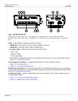
Страница 9: ...Activity Off No link activity Status LEDs for copper Ethernet ports are incorporated into each RJ 45 port For more information refer to Section 3 1 Copper Ethernet Ports Power Supply Terminal Block A pluggable terminal block For more information refer to Section 2 2 Connecting Power Section 4 1 Power Supply Specifications RS 232 Serial Console Port The serial console port is for interfacing direct...

Страница 10: ...RUGGEDCOM RUGGEDCOM RS940G Installation Guide Chapter 1 Introduction Description 4 ...

Страница 11: ...ll render all warranties null and void Changes or modifications not expressly approved by Siemens Canada Ltd could invalidate specifications test results and agency approvals and void the user s authority to operate the equipment IMPORTANT This product should be installed in a restricted access location where access can only be gained by authorized personnel who have been informed of the restricti...

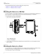
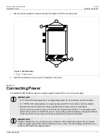
Страница 12: ... bracket allows the device to be slid onto a standard 35 mm 1 4 in DIN rail To mount the device to a DIN rail do the following 1 Align the slot in the bracket with the DIN rail 1 1 2 Figure 2 DIN Rail Mounting 1 DIN Rail 2 DIN Rail Bracket 2 Pull the release on the bracket down and slide the device onto the DIN rail Let go of the release to lock the device in position Section 2 1 2 Mounting the De...

Страница 13: ...talled For 125 250 VDC rated equipment an appropriately rated DC circuit breaker must be installed Equipment must be installed according to applicable local wiring codes and standards All line to ground transient energy is shunted to the Surge Ground terminal In cases where users require the inputs to be isolated from ground remove the ground braid between Surge and Chassis Ground Note that all li...

Страница 14: ...nnect a high AC DC power supply to the device do the following CAUTION Electrical hazard risk of damage to equipment Do not connect AC power cables to terminals for DC power Damage to the power supply may occur CAUTION Electrical hazard risk of damage to equipment Before testing the dielectric strength HIPOT in the field remove the braided ground cable connected to the surge ground terminal and ch...

Страница 15: ...ock 3 Using a braided wire or other appropriate grounding wire connect the surge ground terminal to the chassis ground connection The surge ground terminal is used as the ground conductor for all surge and transient suppression circuitry internal to the unit 4 Connect the ground terminal on the power source to the chassis ground terminal on the device Section 2 2 2 Connecting Low DC Power To conne...

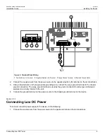
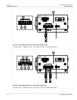
Страница 16: ... 2 4 Figure 5 Terminal Block Wiring Single DC Power Supply Inputs 1 Positive Terminal 2 Negative Terminal 3 Surge Ground Terminal 4 Braided Ground Cable 1 3 1 2 2 4 Figure 6 Terminal Block Wiring Dual DC Power Supply Inputs 1 Positive Terminal 2 Negative Terminal 3 Surge Ground Terminal 4 Braided Ground Cable ...

Страница 17: ...is powered and there are no active alarms If the device is not powered or if an active alarm is configured the relay opens the NO contact and closes the NC Normally Closed contact NOTE Control of the failsafe relay output is configurable through ROS One common application for this relay is to signal an alarm if a power failure occurs For more information refer to the ROS User Guide for the RUGGEDC...

Страница 18: ...ch and access the ROS console and Web interfaces via the device s IP address For more information about available ports refer to Chapter 3 Communication Ports Section 2 5 Cabling Recommendations Before connecting the device be aware of the recommendations and considerations outlined in the following sections Section 2 5 1 Protection On Twisted Pair Data Ports Section 2 5 2 Gigabit Ethernet 1000Bas...

Страница 19: ...peration For reliable error free data communication new and pre existing communication paths should be verified for TIA EIA 568 A compliance The following table summarizes the relevant cabling standards Cabling Category 1000Base TX Compliant Required Action 5 No New wiring infrastructure required 5 Yes Verify TIA EIA 568 A compliance 5e Yes No action required New installations should be designed w...

Страница 20: ...RUGGEDCOM RUGGEDCOM RS940G Installation Guide Chapter 2 Installing the Device Gigabit Ethernet 1000Base TX Cabling Recommendations 14 ...

Страница 21: ...RS940G chassis 1 2 Figure 9 Port Assignment 1 Ports 1 to 6 2 Ports 7 to 8 Port Type 1 to 6 Copper Gigabit Ethernet Ports 10 100 1000Base TX 7 to 8 Fixed SFP or GBIC Gigabit Ethernet Ports 1000Base SX or 1000Base LX The following sections describe the available ports Section 3 1 Copper Ethernet Ports Section 3 2 Fiber Optic Ethernet Ports Section 3 3 SFP Optic Ethernet Ports Section 3 1 Copper Ethe...

Страница 22: ... Mbps Yellow Solid Link established Yellow Blinking Link activity Link Activity Off No link detected The following is the pin out for the RJ45 male connectors 1 8 Figure 11 RJ45 Ethernet Port Pin Configuration Name Pin 10 100Base TX 1000Base TX Description 1 RX BI_DB Receive Data or Bi Directional 2 RX BI_DB Receive Data or Bi Directional 3 TX BI_DA Transmit Data or Bi Directional 4 Reserved Do No...

Страница 23: ...ach port are properly connected and matched to establish a proper link 2 1 Figure 14 LC Port 1 Tx Connector 2 Rx Connector NOTE SFP modules as well as their optical ports can be safely inserted and removed while the chassis is powered and operating The following sections describe how to install and remove SFP optical ports Section 3 3 1 Installing an SFP Optical Port Section 3 3 2 Removing an SFP ...

Страница 24: ...ule 3 Remove the port from its packaging 4 Insert the port into the module and swing the bail latch up to lock it in place 2 1 Figure 15 Installing an SFP Optical Port Typical 1 SFP Optical Port 2 Metal Bail Latch 5 Remove the dust cover from the port 6 Connect a cable to the port and test the connection Section 3 3 2 Removing an SFP Optical Port To remove an SFP optical port do the following CAUT...

Страница 25: ...Removing an SFP Optical Port 19 2 1 Figure 16 Removing an SFP Optical Port Typical 1 SFP Optical Port 2 Metal Bail Latch 4 Store the port in an ESD safe bag or other suitable ESD safe environment free from moisture and stored at the proper temperature 40 to 85 C or 40 to 185 F ...

Страница 26: ...RUGGEDCOM RUGGEDCOM RS940G Installation Guide Chapter 3 Communication Ports Removing an SFP Optical Port 20 ...

Страница 27: ...ds Section 4 6 Operating Environment Section 4 7 Mechanical Specifications Section 4 1 Power Supply Specifications Input Range Power Supply Type Minimum Maximum Internal Fuse Rating ab Isolation Maximum Power Consumption c 88 VDC 300 VDC 4 kVAC HI 85 VAC 264 VAC 2 0 A T 5 5 kVDC 24 VDC 10 VDC 36 VDC 48 36 VDC 72 VDC 3 15 A T 1 5 kVDC 18 W a F denotes fast acting fuse b T denotes time delay fuse c ...

Страница 28: ...ons for fiber Ethernet ports that can be ordered with the RUGGEDCOM RS940G NOTE All optical power numbers are listed as dBm averages To convert from average to peak add 3 dBm To convert from peak to average subtract 3 dBm Maximum segment length is greatly dependent on factors such as fiber quality and the number of patches and splices Consult a Siemens sales associate when determining maximum segm...

Страница 29: ...l o All optical power numbers are listed as dBm averages p Typical distance The maximum segment length is greatly dependent on factors such as fiber quality and the number of patches and splices Consult a Siemens sales associates when determining maximum segment distances q Operating temperature range of 10 to 85 C 14 to 185 F r Operating temperature range of 20 to 85 C 4 to 185 F Section 4 5 Supp...

Страница 30: ...Specifications Parameter Range Comments Ambient Storage Temperature 40 to 85 C 40 to 185 F Section 4 7 Mechanical Specifications Parameter Value Dimensions Refer to Chapter 5 Dimension Drawings Weight 1 2 kg 2 7 lbs Ingress Protection IP40 1 mm or 0 04 in objects Enclosure 20 AWG Galvanized Steel ...

Страница 31: ...DCOM RS940G Installation Guide Chapter 5 Dimension Drawings 25 Dimension Drawings NOTE All dimensions are in millimeters unless otherwise stated 187 96 168 66 83 54 65 13 116 59 7 87 99 06 Figure 17 Overall Dimensions ...

Страница 32: ...Chapter 5 Dimension Drawings RUGGEDCOM RUGGEDCOM RS940G Installation Guide 26 13 64 141 63 101 60 183 89 83 82 1 Figure 18 Panel and DIN Rail Mount Dimensions 1 SFP Port Reference ...

Страница 33: ...ormity Route FCC FCC Part 15 Class A Approved FDA CDRH 21 CFR Chapter I Sub chapter J Approved Section 6 2 FCC Compliance This equipment has been tested and found to comply with the limits for a Class A digital device pursuant to Part 15 of the FCC Rules These limits are designed to provide reasonable protection against harmful interference when the equipment is operated in a commercial environmen...

Страница 34: ...ge AC Power ports 4 kV line to earth 2 kV line to line 4 Signal ports 10 V 3 D C Power ports 10 V 3 AC Power ports 10 V 3 IEC 61000 4 6 Induced Conducted RFI Earth ground ports 10 V 3 IEC 61000 4 8 Magnetic Field Enclosure ports 40 A m continuous 1000 A m for 1 s DC Power ports 30 for 0 1 s 60 for 0 1 s 100 for 0 05 s IEC 61000 4 29 30 for 1 period 60 for 50 periods IEC 61000 4 11 Voltage Dips and...

Страница 35: ...on Test Levels Enclosure Contact 8 kV C37 90 3 9 ESD Enclosure Air 15 kV C37 90 2 8 Radiated RFI Enclosure ports 35 V m Signal ports 4 kV 2 5 kHz DC Power ports 4 kV AC Power ports 4 kV Fast Transient Earth ground ports 4 kV Signal ports 2 5 kV common mode 1MHz DC Power ports 2 5 kV common and differential mode 1MHz C37 90 1 7 Oscillatory AC Power ports 2 5 kV common and differential mode 1MHz Sig...

Страница 36: ...on Guide 30 EMI and Environmental Type Tests Test Description Test Levels Severity Levels IEC 60068 2 30 Humidity Damp Heat Cyclic Test Db 95 non condensing 55 C 131 F 6 cycles IEC 60255 21 1 Vibration 2 g 10 150 Hz Class 2 IEC 60255 21 2 Shock 30 g 11 ms Class 2 ...

Отзывы: