background image

Chapter 2

Using ROS

RUGGEDCOM ROS

User Guide

46

Defragmenting the Flash File System

flashfiles

 info  

filename

Where:

filename


 is the name of the file stored in Flash memory

Details, similar to the following, are displayed.

>flashfiles info main.bin

Flash file information for main.bin:

Header version   : 4

Platform         : ROS-CF52

File name        : main.bin

Firmware version : v4.3.0

Build date       : Sep 27 2014 15:50

File length      : 2624659

Board IDs        :  3d

Header CRC       : 73b4

Header CRC Calc  : 73b4

Body CRC         : b441

Body CRC Calc    : b441

Section 2.8.3

Defragmenting the Flash File System

The flash memory is defragmented automatically whenever there is not enough memory available for a binary

upgrade. However, fragmentation can occur whenever a new file is uploaded to the unit. Fragmentation causes

sectors of available memory to become separated by ones allocated to files. In some cases, the total available

memory might be sufficient for a binary upgrade, but that memory may not be available in one contiguous region.
To defragment the flash memory, do the following:
1. Log in to the device as an admin user and access the CLI shell. For more information about accessing the CLI

shell, refer to 

 Section 2.6, “Using the Command Line Interface” 

.

2. Defragment the flash memory by typing:

flashfiles

 defrag

Section 2.9

Accessing BIST Mode

BIST (Built-In-Self-Test) mode is used by service technicians to test and configure internal functions of the device.

It should only be accessed for troubleshooting purposes.

CAUTION!

Mechanical hazard – risk of damage to the device. Excessive use of BIST functions may cause increase

wear on the device, which may void the warranty. Avoid using BIST functions unless instructed by a

Siemens Customer Support representative.

To access BIST mode, do the following:

Содержание RUGGEDCOM ROS v4.3

Страница 1: ...RUGGEDCOM ROS v4 3 User Guide For RS900 07 2016 Preface Introduction 1 Using ROS 2 Device Management 3 System Administration 4 Setup and Configuration 5 Troubleshooting 6 RC1275 EN 03 ...

Страница 2: ...l might be trademarks whose use by third parties for their own purposes would infringe the rights of the owner Third Party Copyrights Siemens recognizes the following third party copyrights Copyright 2004 GoAhead Software Inc All Rights Reserved Open Source RUGGEDCOM ROS contains Open Source Software For license conditions refer to the associated License Conditions document Security Information Si...

Страница 3: ...emens Address Siemens Canada Ltd Industry Sector 300 Applewood Crescent Concord Ontario Canada L4K 5C7 Telephone Toll free 1 888 264 0006 Tel 1 905 856 5288 Fax 1 905 856 1995 E mail ruggedcom info i ia siemens com Web www siemens com ruggedcom ...

Страница 4: ...RUGGEDCOM ROS User Guide iv ...

Страница 5: ...L Certificates 6 1 2 2 2 SSH Key Pairs 8 1 3 Supported Networking Standards 9 1 4 Port Numbering Scheme 9 1 5 Available Services by Port 10 1 6 SNMP Management Interface Base MIB Support 12 1 6 1 Supported Standard MIBs 12 1 6 2 Supported Proprietary RUGGEDCOM MIBs 13 1 6 3 Supported Agent Capabilities 13 1 7 SNMP Traps 14 1 8 ModBus Management Support 16 1 8 1 ModBus Function Codes 16 1 8 2 ModBu...

Страница 6: ...otely via RSH 40 2 6 4 Using SQL Commands 40 2 6 4 1 Finding the Correct Table 41 2 6 4 2 Retrieving Information 41 2 6 4 3 Changing Values in a Table 43 2 6 4 4 Resetting a Table 44 2 6 4 5 Using RSH and SQL 44 2 7 Selecting Ports in RUGGEDCOM ROS 44 2 8 Managing the Flash File System 45 2 8 1 Viewing a List of Flash Files 45 2 8 2 Viewing Flash File Details 45 2 8 3 Defragmenting the Flash File ...

Страница 7: ...2 Viewing the Status of Ethernet Ports 67 3 6 3 Viewing Statistics for All Ethernet Ports 68 3 6 4 Viewing Statistics for Specific Ethernet Ports 68 3 6 5 Clearing Statistics for Specific Ethernet Ports 71 3 6 6 Configuring an Ethernet Port 72 3 6 7 Configuring Port Rate Limiting 74 3 6 8 Configuring Port Mirroring 76 3 6 9 Configuring Link Detection 77 3 6 10 Detecting Cable Faults 79 3 6 10 1 Vi...

Страница 8: ...Chapter 4 System Administration 111 4 1 Configuring the System Information 111 4 2 Customizing the Login Screen 112 4 3 Configuring Passwords 112 4 4 Clearing Private Data 115 4 5 Enabling Disabling the Web Interface 116 4 6 Managing Alarms 116 4 6 1 Viewing a List of Pre Configured Alarms 117 4 6 2 Viewing and Clearing Latched Alarms 118 4 6 3 Configuring an Alarm 118 4 6 4 Authentication Related...

Страница 9: ...VLANs Globally 141 5 1 4 Configuring VLANs for Specific Ethernet Ports 143 5 1 5 Managing Static VLANs 145 5 1 5 1 Viewing a List of Static VLANs 145 5 1 5 2 Adding a Static VLAN 145 5 1 5 3 Deleting a Static VLAN 147 5 2 Managing Spanning Tree Protocol 148 5 2 1 RSTP Operation 148 5 2 1 1 RSTP States and Roles 149 5 2 1 2 Edge Ports 151 5 2 1 3 Point to Point and Multipoint Links 152 5 2 1 4 Path...

Страница 10: ...pecific Ethernet Ports 182 5 3 3 Configuring Priority to CoS Mapping 184 5 3 4 Configuring DSCP to CoS Mapping 185 5 4 Managing MAC Addresses 186 5 4 1 Viewing a List of MAC Addresses 187 5 4 2 Configuring MAC Address Learning Options 188 5 4 3 Configuring MAC Address Flooding Options 188 5 4 4 Managing Static MAC Addresses 190 5 4 4 1 Viewing a List of Static MAC Addresses 190 5 4 4 2 Adding a St...

Страница 11: ... 8 1 2 Viewing a List of Multicast Group Memberships 221 5 8 1 3 Viewing Forwarding Information for Multicast Groups 222 5 8 1 4 Configuring IGMP 223 5 8 2 Managing GMRP 224 5 8 2 1 GMRP Concepts 225 5 8 2 2 Viewing a Summary of Multicast Groups 227 5 8 2 3 Configuring GMRP Globally 227 5 8 2 4 Configuring GMRP for Specific Ethernet Ports 228 5 8 2 5 Viewing a List of Static Multicast Groups 230 5...

Страница 12: ...2 Features 242 5 10 1 3 Link Aggregation and Physical Layer Features 243 5 10 2 Managing Port Trunks 243 5 10 2 1 Viewing a List of Port Trunks 243 5 10 2 2 Adding a Port Trunk 244 5 10 2 3 Deleting a Port Trunk 245 Chapter 6 Troubleshooting 247 6 1 General 247 6 2 Ethernet Ports 248 6 3 Spanning Tree 248 6 4 VLANs 249 ...

Страница 13: ...p text included in the software Conventions This User Guide uses the following conventions to present information clearly and effectively Alerts The following types of alerts are used when necessary to highlight important information DANGER DANGER alerts describe imminently hazardous situations that if not avoided will result in death or serious injury WARNING WARNING alerts describe hazardous sit...

Страница 14: ...arameters are presented in the order they must be entered Related Documents Other documents that may be of interest include RUGGEDCOM RS900 Installation Guide System Requirements Each workstation used to connect to the RUGGEDCOM ROS interface must meet the following system requirements Must have one of the following Web browsers installed Microsoft Internet Explorer 8 0 or higher Mozilla Firefox G...

Страница 15: ...visit www siemens com ruggedcom or contact a Siemens Sales representative Customer Support Customer support is available 24 hours 7 days a week for all Siemens customers For technical support or general information contact Siemens Customer Support through any of the following methods Online Visit http www siemens com automation support request to submit a Support Request SR or check on the status ...

Страница 16: ...RUGGEDCOM ROS User Guide Preface Customer Support xvi ...

Страница 17: ...mission critical applications and where high reliability is of paramount importance Key RUGGEDCOM ROS features that address security issues at the local area network level include Passwords Multi level user passwords secures against unauthorized configuration SSH SSL Extends capability of password protection to add encryption of passwords and data as they cross the network Enable Disable Ports Cap...

Страница 18: ...solution can record traps from multiple devices providing a powerful network troubleshooting tool It also provides a graphical visualization of the network and is fully integrated with all Siemens products Remote Monitoring and Configuration with RUGGEDCOM NMS RUGGEDCOM NMS RNMS is Siemens s Network Management System software for the discovery monitoring and management of RUGGEDCOM products and ot...

Страница 19: ...or configuration and monitoring via a standard graphical Web browser or via a standard telcom user interface All system parameters include detailed online help to make setup a breeze RUGGEDCOM ROS presents a common look and feel and standardized configuration process allowing easy migration to other managed RUGGEDCOM products Brute Force Attack Prevention Protection against Brute Force Attacks BFA...

Страница 20: ...ure configuration files are properly protected when they exist outside of the device For instance encrypt the files store them in a secure place and do not transfer them via insecure communication channels Management of the configuration file certificates and keys is the responsibility of the device owner Consider using RSA key sizes of at least 2048 bits in length and certificates signed with SHA...

Страница 21: ... NOTE For configuration compatibility reasons the configured setting will not change when upgrading from RUGGEDCOM ROS versions older than v4 2 0 to v4 2 0 and newer This setting is always enabled and cannot be configured on versions before v4 2 0 For new units with firmware v4 2 0 this setting is configurable and disabled by default Policy Periodically audit the device to make sure it complies wi...

Страница 22: ...OS Non Controlled NC verions RSA key pair 512 to 2048 bits The RSA key pair used in the default certificate and in those generated by RUGGEDCOM ROS uses a public key of 1024 bits in length NOTE RSA keys smaller than 2048 bits in length are not recommended Support is only included here for compatibility with legacy equipment NOTE The default certificate and keys are common to all RUGGEDCOM ROS vers...

Страница 23: ...or use with RUGGEDCOM ROS in a Microsoft Windows environment refer to the following Siemens application note Creating Uploading SSH Keys and SSL Certificates to ROS Using Windows The following is an example of a self signed SSL certificate generated by RUGGEDCOM ROS Certificate Data Version 3 0x2 Serial Number ca 01 2d c0 bf f9 fd f2 Signature Algorithm sha1WithRSAEncryption Issuer C CA ST Ontario...

Страница 24: ...in length NOTE DSA or RSA keys smaller than 2048 bits in length are not recommended and support is only included here for compatibility with legacy equipment NOTE DSA RSA key generation times increase depending on the key length 1024 bit RSA keys may take several minutes to generate whereas 2048 bit keys may take significantly longer A typical modern PC system however can generate these keys in se...

Страница 25: ... ea f1 74 55 2b de 61 6c fd dd f5 e1 c5 03 68 b4 ad 40 48 58 62 6c 79 75 b1 5d 42 e6 a9 97 86 37 d8 1e e5 65 09 28 86 2e 6a d5 3d 62 50 06 b8 d3 f9 d4 9c 9c 75 84 5b db 96 46 13 f0 32 f0 c5 cb 83 01 a8 ae d1 5a ac 68 fb 49 f9 b6 8b d9 d6 0d a7 de ad 16 2b 23 ff 8e f9 3c 41 16 04 66 cf e8 64 9e e6 42 9a d5 97 60 c2 e8 9e f4 bc 8f 6f e0 Section 1 3 Supported Networking Standards The following networ...

Страница 26: ...es The service supported by the device Port Number The port number associated with the service Port Open The port state whether it is always open and cannot be closed or open only but can be configured NOTE In certain cases the service might be disabled but the port can still be open e g TFTP Port Default The default state of the port i e open or closed Access Authorized Denotes whether the ports ...

Страница 27: ...e through two management interfaces SNTP UDP 123 Enabled configurable No Only available through two management interfaces SSH TCP 22 Enabled Yes Only available through two management interfaces ICMP Enabled No TACACS TCP 49 configurable Disabled configurable Yes RADIUS UDP 1812 to send configurable opens random port to listen to Disabled configurable Yes Only available through two management inter...

Страница 28: ...andard MIBs Standard MIB Name Title RFC 2578 SNMPv2 SMI Structure of Management Information Version 2 RFC 2579 SNMPv2 TC Textual Convention s for SMIv2 SNMPv2 CONF Conformance Statements for SMIv2 RFC 2580 IANAifType Enumerated Values of the ifType Object Defined ifTable defined in IF MIB RFC 1907 SNMPv2 MIB Management Information Base for SNMPv2 RFC 2011 IP MIB SNMPv2 Management Information Base ...

Страница 29: ...naged Objects for Bridges with Traffic Classes Multicast Filtering and Virtual LAN Extensions Section 1 6 2 Supported Proprietary RUGGEDCOM MIBs RUGGEDCOM ROS supports the following proprietary RUGGEDCOM MIBs File Name MIB Name Description RUGGEDCOM MIB mib RUGGEDCOM MIB RUGGEDCOM enterprise SMI RUGGEDCOM TRAPS MIB mib RUGGEDCOM TRAPS MIB RUGGEDCOM traps definition RUGGEDCOM SYS INFO MIB mib RUGGE...

Страница 30: ...P MIB AC LLDP MIB RC LAG MIB AC mib RC LAG MIB AC IEEE8023 LAG MIB RC_RSTP MIB AC mib RC_RSTP MIB AC RSTP MIB RC RUGGEDCOM DOT11 MIB AC mib RC RUGGEDCOM DOT11 MIB AC RUGGEDCOM DOT11 MIB RC RUGGEDCOM POE MIB AC mib RC RUGGEDCOM POE MIB AC RUGGEDCOM POE MIB RC RUGGEDCOM STP AC MIB mib RC RUGGEDCOM STP AC MIB RUGGEDCOM STP MIB RC RUGGEDCOM SYS INFO MIB AC mib RC RUGGEDCOM SYS INFO MIB AC RUGGEDCOM SY...

Страница 31: ... can be retrieved using the CLI command alarms For more information about the alarms command refer to Section 2 6 1 Available CLI Commands Table Generic Traps Trap Severity heap error Alert NTP server failure notification real time clock failure Error failed password Warning MAC address not learned by switch fabric Warning BootP client TFTP transfer failure Error received looped back BPDU Error re...

Страница 32: ...ModBus Memory Map Section 1 8 3 ModBus Memory Formats Section 1 8 1 ModBus Function Codes RUGGEDCOM devices support the following ModBus function codes for device management through ModBus NOTE While RUGGEDCOM devices have a variable number of ports not all registers and bits apply to all products Registers that are not applicable to a particular device return a zero 0 value For example registers ...

Страница 33: ...ory Map The following details how ModBus process variable data is mapped Product Info The following data is mapped to the Productinfo table Address Registers Description Reference Table in UI R W Format 0000 16 Product Identification R Text 0010 32 Firmware Identification R Text 0040 1 Number of Ethernet Ports R Uint16 0041 1 Number of Serial Ports R Uint16 0042 1 Number of Alarms R Uint16 0043 1 ...

Страница 34: ... data is mapped to the ethPortStats table Address Registers Description Reference Table in UI R W Format 03FE 2 Port Link Status R PortCmd Ethernet Statistics The following data is mapped to the rmonStats table Address Registers Description Reference Table in UI R W Format 0400 2 Port s1 p1 Statistics Ethernet In Packets R Uinst32 0402 2 Port s1 p2 Statistics Ethernet In Packets R Uinst32 0404 2 P...

Страница 35: ... Statistics Ethernet In Packets R Uinst32 0430 2 Port s7 p1 Statistics Ethernet In Packets R Uinst32 0432 2 Port s7 p2 Statistics Ethernet In Packets R Uinst32 0434 2 Port s8 p1 Statistics Ethernet In Packets R Uinst32 0436 2 Port s8 p2 Statistics Ethernet In Packets R Uinst32 0440 2 Port s1 p1 Statistics Ethernet Out Packets R Uinst32 0442 2 Port s1 p2 Statistics Ethernet Out Packets R Uinst32 04...

Страница 36: ...2 2 Port s1 p2 Statistics Ethernet In Packets R Uinst32 0484 2 Port s1 p3 Statistics Ethernet In Packets R Uinst32 0486 2 Port s1 p4 Statistics Ethernet In Packets R Uinst32 0488 2 Port s2 p1 Statistics Ethernet In Packets R Uinst32 048A 2 Port s2 p2 Statistics Ethernet In Packets R Uinst32 048C 2 Port s2 p3 Statistics Ethernet In Packets R Uinst32 048E 2 Port s2 p4 Statistics Ethernet In Packets ...

Страница 37: ...4 Statistics Ethernet Out Packets R Uinst32 04D0 2 Port s3 p1 Statistics Ethernet Out Packets R Uinst32 04D2 2 Port s3 p2 Statistics Ethernet Out Packets R Uinst32 04D4 2 Port s3 p3 Statistics Ethernet Out Packets R Uinst32 04D6 2 Port s3 p4 Statistics Ethernet Out Packets R Uinst32 04D8 2 Port s4 p1 Statistics Ethernet Out Packets R Uinst32 04DA 2 Port s4 p2 Statistics Ethernet Out Packets R Uins...

Страница 38: ...ics Serial Out characters R Uint32 0644 2 Port 3 Statistics Serial Out characters R Uint32 0646 2 Port 4 Statistics Serial Out characters R Uint32 0680 2 Port 1 Statistics Serial In Packets R Uint32 0682 2 Port 2 Statistics Serial In Packets R Uint32 0684 2 Port 3 Statistics Serial In Packets R Uint32 0686 2 Port 4 Statistics Serial In Packets R Uint32 06C0 2 Port 1 Statistics Serial Out Packets R...

Страница 39: ... of the characters for the product identification which reads as SYSTEM NAME Since the length of this field is smaller than eight registers the rest of the field is filled with zeros 0 Section 1 8 3 2 Cmd The Cmd format instructs the device to set the output to either true or false The most significant byte comes first FF 00 hex requests output to be True 00 00 hex requests output to be False Any ...

Страница 40: ...ta Using PortCmd To understand how to read data using PortCmd consider a ModBus Request to read multiple registers from locatoin 0x03FE 0x04 0x03 0xFE 0x00 0x02 The response depends on how many parts are available on the device For example if the maximum number of ports on a connected RUGGEDCOM device is 20 the response would be similar to the following 0x04 0x04 0xF2 0x76 0x00 0x05 In this exampl...

Страница 41: ... 0 1 Power Supply 1 Status Bits 2 3 Power Supply 2 Status Other bits in the register do not provide any system status information Bit Value Description 01 Power Supply not present 01 1 10 Power Supply is functional 10 2 11 Power Supply is not functional 11 3 The values used for power supply status are derived from the RUGGEDCOM specific SNMP MIB Reading the Power Supply Status from a Device Using ...

Страница 42: ...x04 0x00 0x45 0x00 0x01 The response may look like 0x04 0x02 0x00 0x01 The register s lower byte shows the ErrorAlarm status In this example there is no active ERROR ALERT or CRITICAL alarm in the device Section 1 9 SSH and SSL Keys and Certificates The following describes the SSH and SSL keys and certificates in RS900 along with the certificate and SSH key requirements CONTENTS Section 1 9 1 Cert...

Страница 43: ...ificates and keys are being generated the generator will abort and the custom certificate and keys and will be used User Generated Recommended Custom certificates and keys are the most secure option They give the user complete control over certificate and key management allow for the provision of certificates signed by a public or local certificate authority enable strictly controlled access to pr...

Страница 44: ...t6skkCD1xmxA6XG64hR3BfxFSZcew Wr4SOFGCtQJBAMurr5FYPJRFGzPM3HwcpAaaMIUtPwNyTtTjywlYcUI7iZVVfbdx 4B7qOadPybTg7wqUrGVkPSzzQelz9YCSSV8CQFqpIsEYhbqfTLZEl83YjsuaE801 xBivaWLIT0b2TvM2O7zSDOG5fv4I990v mgrQRtmeXshVmEChtKnBcm7HH0CQE6B 2WUfLArDMJ8hAoRczeU1nipXrIh5kWWCgQsTKmUrafdEQvdpT8ja5GpX2Rp98eaU NHfI0cP36JpCdome2eUCQDZN9OrTgPfeDIXzyOiUUwFlzS1idkUGL9nH86iuPnd7 WVF3rV9Dse30sVEk63Yky8uKUy7yPUNWldG4U5vRKmY E...

Страница 45: ...e various methods for connecting the device CONTENTS Section 2 1 1 Connecting Directly Section 2 1 2 Connecting via the Network Section 2 1 1 Connecting Directly RUGGEDCOM ROS can be accessed through a direct RS 232 serial console connection for management and troubleshooting purposes A console connection provides access to the console interface and CLI To establish a console connection to the dev...

Страница 46: ...b browser do the following 1 On the workstation being used to access the device configure an Ethernet port to use an IP address falling within the subnet of the device The default IP address is 192 168 0 1 24 For example to configure the device to connect to one of the available Ethernet ports assign an IP address to the Ethernet port on the workstation in the range of 192 168 0 3 to 192 168 0 254...

Страница 47: ...ct the service i e Telnet RSH or SSH 2 Enter the IP address for the port that is connected to the network 3 Connect to the device Once the connection is established the login form appears For more information about logging in to the device refer to Section 2 2 Logging In Section 2 2 Logging In To log in to the device do the following 1 Connect to the device either directly or through a Web browser...

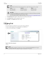
Страница 48: ...ng passwords refer to Section 4 3 Configuring Passwords 2 In the User Name field type the username for an account setup on the device 3 In the Password field typ the password for the account 4 Click Enter or click Submit Web interface only Section 2 3 Logging Out To log out of the device navigate to the main screen and do the following To log out of the Console or secure shell interfaces press CTR...

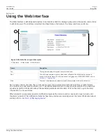
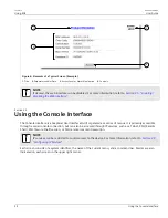
Страница 49: ... For information about logging out of RUGGEDCOM ROS refer to Section 2 3 Logging Out Main The main frame displays the parameters and or data related to the selected feature Each screen consists of a title the current user s access level parameters and or data in form or table format and controls e g add delete refresh etc The title provides access to context specific Help for the screen that provi...

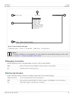
Страница 50: ...ce The Console interface is a Graphical User Interface GUI organized as a series of menus It is primarily accessible through a serial console connection but can also be accessed through IP services such as a Telnet RSH Remote Shell SSH Secure Shell session or SSH remote command execution NOTE IP services can be restricted to control access to the device For more information refer to Section 3 9 Co...

Страница 51: ...nterface Use the following controls to navigate between screens in the Console interface Enter Select a menu item and press this Enter to enter the sub menu or screen beneath Esc Press Esc to return to the previous screen Configuring Parameters Use the following controls to select and configure parameters in the Console interface Up Down Arrow Keys Use the up and down arrow keys to select paramete...

Страница 52: ...parameter Section 2 6 Using the Command Line Interface The Command Line Interface CLI offers a series of powerful commands for updating ROS generating certificates keys tracing events troubleshooting and much more It is accessed via the Console interface by pressing Ctrl S CONTENTS Section 2 6 1 Available CLI Commands Section 2 6 2 Tracing Events Section 2 6 3 Executing Commands Remotely via RSH S...

Страница 53: ...t the flashfiles command refer to Section 2 8 Managing the Flash File System flashleds timeout Flashes the LED indicators on the device for a specified number of seconds Optional and or required parameters include timeout is the number of seconds to flash the LED indicators To stop the LEDs from flashing set the timeout period to 0 zero fpgacmd Provides access to the FPGA management tool for troub...

Страница 54: ... If optional or required parameters are not used this command displays the base and extended information Optional and or required parameters include port is the port number for which the data are required base displays the base information alarms displays alarms and warning flags diag displays measured data calibr displays calibration data for external calibration thr displays thresholds data all ...

Страница 55: ...s the contents of a text file Optional and or required parameters include filename is the name of the file to be read version Prints the software version xmodem send receive filename Opens an XModem session Optional and or required parameters include send sends the file to the client receive receives the file from the client filename is the name of the file to be read Section 2 6 2 Tracing Events ...

Страница 56: ...ere entered at the CLI prompt The syntax of the RSH command is usually of the form rsh ipaddr l auth_token command_string Where ipaddr is the address or resolved name of the device auth_token is the user name i e guest operator or admin and corresponding password separated by a comma For example admin secret command_string is the RUGGEDCOM ROS CLI command to execute NOTE The access level correspon...

Страница 57: ...alues in a Table Section 2 6 4 4 Resetting a Table Section 2 6 4 5 Using RSH and SQL Section 2 6 4 1 Finding the Correct Table Many SQL commands operate upon specific tables in the database and require the table name to be specified Navigating the menu system in the console interface to the desired menu and pressing Ctrl Z displays the name of the table The menu name and the corresponding database...

Страница 58: ...e must be the same as it is displayed in the menu system unless the name contains spaces e g ip address Spaces must be replaced with underscores e g ip_address or the parameter name must be wrapped in double quotes e g ip address sql select parameter from table Where parameter is the name of the parameter table is the name of the table Example sql select ip address from ipSwitchIfCfg IP Address 19...

Страница 59: ...px FlowCtrl LFI Alarm 1 Port 1 1 1000T Enabled On Auto Auto Off Off on 2 Port 2 2 1000T Enabled On Auto Auto Off Off On 3 Port 3 3 1000T Enabled On Auto Auto Off Off On 4 Port 4 4 1000T Enabled On Auto Auto Off Off On 4 records selected Section 2 6 4 3 Changing Values in a Table Use the following command to change the value of parameters in a table sql update table set parameter value Where table ...

Страница 60: ...C type Devices 10 0 1 1 10 0 1 2 C for F i in devices do rsh i l admin admin sql select from ipAddrtable C rsh 10 0 1 1 l admin admin sql select from ipAddrtable IP Address Subnet IfIndex IfStats IfTime IfName 192 168 0 31 255 255 255 0 1001 274409096 2218 vlan1 1 records selected C rsh 10 0 1 2 l admin admin sql select from ipAddrtable 0 records selected C Section 2 7 Selecting Ports in RUGGEDCOM...

Страница 61: ...Type flashfiles A list of files currently in Flash memory is displayed along with their locations and the amount of memory they consume For example flashfiles Filename Base Size Sectors Used boot bin 00000000 110000 0 16 1095790 main bin 00110000 140000 17 36 1258403 fpga xsvf 00250000 010000 37 37 55882 syslog txt 00260000 140000 38 57 19222 ssh keys 003A0000 010000 58 58 915 ssl crt 003B0000 010...

Страница 62: ...ailable memory to become separated by ones allocated to files In some cases the total available memory might be sufficient for a binary upgrade but that memory may not be available in one contiguous region To defragment the flash memory do the following 1 Log in to the device as an admin user and access the CLI shell For more information about accessing the CLI shell refer to Section 2 6 Using the...

Страница 63: ...e i e flash files on RUGGEDCOM ROS devices and are retrieved at the time of SSH client authentication CONTENTS Section 2 10 1 Adding a Public Key Section 2 10 2 Viewing a List of Public Keys Section 2 10 3 Updating a Public Key Section 2 10 4 Deleting a Public Key Section 2 10 1 Adding a Public Key Admin users can add one or more public keys to RUGGEDCOM ROS Public keys are stored in a flash file ...

Страница 64: ...XLJK1koJPbDjH7yFFC7mwK2eMU oMFFn934cbO5N6etsJSvplYQ4pMCw6Ok8Q bB5cPSOa rAt bob work IMPORTANT The content of the sshaddpub keys file must follow the same syntax as the sshpub keys file RUGGEDCOM ROS allows only 16 user key entries to be stored Each key entry must meet the following limits Key type must be either RSA 2048 bits or RSA 3072 bits Key size must not exceed 4000 base64 encoded characters...

Страница 65: ...admin user and access the CLI shell For more information about accessing the CLI shell refer to Section 2 6 Using the Command Line Interface 2 At the CLI prompt type sshpubkey list A list of public keys will appear including their key ID access level revocation status user name and key fingerprint 3 Type the following commands to update the public keys Command Description sshpubkey update_id curre...

Страница 66: ...he CLI shell For more information about accessing the CLI shell refer to Section 2 6 Using the Command Line Interface 2 At the CLI prompt type sshpubkey list A list of public keys will appear including access level revocation status user name and key fingerprint 3 Type the following commands to delete the public key s Command Description sshpubkey remove ID Removes a key from the non volatile stor...

Страница 67: ... Uploading Downloading Files Section 3 5 Managing Logs Section 3 6 Managing Ethernet Ports Section 3 7 Managing IP Interfaces Section 3 8 Managing IP Gateways Section 3 9 Configuring IP Services Section 3 10 Managing Remote Monitoring Section 3 11 Upgrading Downgrading Firmware Section 3 12 Resetting the Device Section 3 13 Decommissioning the Device Section 3 1 Viewing Product Information During ...

Страница 68: ...Controlled release The value Non Controlled indicates the main firmware is a Non Controlled release The Controlled main firmware can run on Controlled units but it can not run on Non Controlled units The Non Controlled main firmware can run on both Controlled and Non Controlled units Serial Number Synopsis Any 31 characters Shows the serial number of the device Boot Version Synopsis Any 47 charact...

Страница 69: ...rformance navigate to Diagnostics View CPU Diagnostics The CPU Diagnostics form appears 2 10 1 3 4 5 6 7 8 9 Figure 9 CPU Diagnostics Form 1 Running Time Box 2 Total Powered Time Box 3 CPU Usage Box 4 RAM Total Box 5 RAM Free Box 6 RAM Low Watermark Box 7 Temperature Box 8 Free Rx Bufs Box 9 Free Tx Bufs Box 10 Reload Button This screen displays the following information Parameter Description Runn...

Страница 70: ... The device can be completely or partially restored to its original factory default settings Excluding groups of parameters from the factory reset such as those that affect basic connectivity and SNMP management is useful when communication with the device is still required during the reset The following categories are not affected by a selective configuration reset IP Interfaces IP Gateways SNMP ...

Страница 71: ...ables that are critical for switch management applications or to force All tables to default settings 3 Click Apply Section 3 4 Uploading Downloading Files Files can be transferred between the device and a host computer using any of the following methods Xmodem using the CLI shell over a Telnet or RS 232 console session TFTP client using the CLI shell in a console session and a remote TFTP server ...

Страница 72: ...ing Files Using a TFTP Client Section 3 4 3 Uploading Downloading Files Using a TFTP Server Section 3 4 4 Uploading Downloading Files Using an SFTP Server Section 3 4 1 Uploading Downloading Files Using XMODEM To updload or download a file using XMODEM do the following NOTE This method requires a host computer that has terminal emulation or Telnet software installed and the ability to perform XMOD...

Страница 73: ...hly insecure NOTE This method requires a TFTP server that is accessible over the network 1 Identify the IP address of the computer running the TFTP server 2 Establish a direct connection between the device and a host computer For more information refer to Section 2 1 1 Connecting Directly 3 Log in to the device as an admin user and access the CLI shell For more information about accessing the CLI ...

Страница 74: ...ze the TFTP server on the host computer and launch the TFTP transfer The server will indicate when the transfer is complete The following is an example of a successful TFTP server exchange C tftp i 10 1 0 1 put C files ROD CF52_Main_v3 7 0 bin main bin Transfer successful 1428480 bytes in 4 seconds 375617 bytes s Section 3 4 4 Uploading Downloading Files Using an SFTP Server SFTP Secure File Trans...

Страница 75: ... 0 bytes indicates that no unexpected events have occurred The system log contains a record of significant events including startups configuration changes firmware upgrades and database re initializations due to feature additions The system log will accumulate information until it is full holding approximately 2 MB of data CONTENTS Section 3 5 1 Viewing Local Logs Section 3 5 2 Clearing Local Logs...

Страница 76: ...orm appears 1 Figure 12 Clear System Log Form 1 Confirm Button 2 Click Confirm Section 3 5 3 Configuring the Local System Log To configure the severity level for the local system log do the following NOTE For maximum reliability use remote logging For more information refer to Section 3 5 4 Managing Remote Logging 1 Navigate to Administration Configure Syslog Configure Local Syslog The Local Syslo...

Страница 77: ...nt event messages The syslog client resides on the device and supports up to 5 collectors or syslog servers The remote syslog protocol defined in RFC 3164 is a UDP IP based transport that enables the device to send event notification messages across IP networks to event message collectors also known as syslog servers The protocol is designed to simply transport these event messages from the genera...

Страница 78: ...514 The local UDP port through which the client sends information to the server s 3 Click Apply Section 3 5 4 2 Viewing a List of Remote Syslog Servers To view a list of known remote syslog servers navigate to Administration Configure Syslog Configure Remote Syslog Server The Remote Syslog Server table appears Figure 15 Remote Syslog Server Table If remote syslog servers have not been configured a...

Страница 79: ...d a remote syslog server to the list of known servers do the following 1 Navigate to Administration Configure Syslog Configure Remote Syslog Server The Remote Syslog Server table appears 1 Figure 16 Remote Syslog Server Table 1 InsertRecord 2 Click InsertRecord The Remote Syslog Server form appears 7 5 6 4 3 2 1 Figure 17 Remote Syslog Server Form 1 IP Address Box 2 UDP Port Box 3 Facility Box 4 S...

Страница 80: ...psis EMERGENCY ALERT CRITICAL ERROR WARNING NOTICE INFORMATIONAL DEBUGGING Default DEBUGGING The severity level is the severity of the message that has been generated Please note that the severity level user select is accepted as the minimum severity level for the system For example if user selects the severity level as Error then the system send any syslog message originated by Error Critical Ale...

Страница 81: ...remote monitoring for Ethernet ports refer to Section 3 10 Managing Remote Monitoring CONTENTS Section 3 6 1 Controller Protection Through Link Fault Indication LFI Section 3 6 2 Viewing the Status of Ethernet Ports Section 3 6 3 Viewing Statistics for All Ethernet Ports Section 3 6 4 Viewing Statistics for Specific Ethernet Ports Section 3 6 5 Clearing Statistics for Specific Ethernet Ports Secti...

Страница 82: ...on method that tells a link partner when the link integrity signal has stopped Such a method natively exists in some link media but not all 100Base TX 1000Base T 1000Base X Includes a built in auto negotiation feature i e a special flag called Remote Fault Indication is set in the transmitted auto negotation signal 100Base FX Links Includes a standard Far End Fault Indication FEFI feature defined ...

Страница 83: ...ed to the controller after the controller transmits its first frame Section 3 6 2 Viewing the Status of Ethernet Ports To view the current status of each Ethernet port navigate to Ethernet Ports View Port Status The Port Status table appears Figure 21 Port Status Table This table displays the following information Parameter Description Port Synopsis 1 to maximum port number The port number as seen...

Страница 84: ... Synopsis Down Up InOctets Synopsis 0 to 4294967295 The number of octets in received good packets Unicast Multicast Broadcast and dropped packets OutOctets Synopsis 0 to 4294967295 The number of octets in transmitted good packets InPkts Synopsis 0 to 4294967295 The number of received good packets Unicast Multicast Broadcast and dropped packets OutPkts Synopsis 0 to 4294967295 The number of transmi...

Страница 85: ...opsis 0 to 18446744073709551615 The number of transmitted good packets TotalInOctets Synopsis 0 to 18446744073709551615 The total number of octets of all received packets This includes data octets of rejected and local packets which are not forwarded to the switching core for transmission It should reflect all the data octets received on the line TotalInPkts Synopsis 0 to 18446744073709551615 The ...

Страница 86: ...ackets for which Late Collision Event has been detected Pkt64Octets Synopsis 0 to 4294967295 The number of received and transmitted packets with size of 64 octets This includes received and transmitted packets as well as dropped and local received packets This does not include rejected received packets Pkt65to127Octets Synopsis 0 to 4294967295 The number of received and transmitted packets with si...

Страница 87: ...551615 The number of transmitted Multicast packets This does not include Broadcast packets OutBroadcasts Synopsis 0 to 18446744073709551615 The number of transmitted Broadcast packets UndersizePkts Synopsis 0 to 4294967295 The number of received packets which meet all the following conditions Packet data length is less than 64 octets Collision Event has not been detected Late Collision Event has n...

Страница 88: ...t Parameters table appears Figure 25 Port Parameters Table 2 Select an Ethernet port The Port Parameters form appears 7 11 6 5 4 3 2 1 8 12 9 10 Figure 26 Port Parameters Form 1 Port Box 2 Name Box 3 Media Box 4 State Box 5 AutoN Box 6 Speed Box 7 Dupx Box 8 FlowCtrl Box 9 LFI Box 10 Alarm Box 11 Apply Button 12 Reload Button 3 Configure the following parameter s as required Parameter Description ...

Страница 89: ... both end devices must be auto negotiation compliant for the best possible results 10Mbps and 100Mbps fiber optic media do not support auto negotiation so these media must be explicitly configured to either half or full duplex Full duplex operation requires that both ends are configured as such or else severe frame loss will occur during heavy network traffic Speed Synopsis Auto 10M 100M 1G Defaul...

Страница 90: ...that port NOTE If one end of the link is fixed to a specific speed and duplex type and the peer auto negotiates there is a strong possibility that the link will either fail to raise or raise with the wrong settings on the auto negotiating side The auto negotiating peer will fall back to half duplex operation even when the fixed side is full duplex Full duplex operation requires that both ends are ...

Страница 91: ...eter Description Port Synopsis 1 to maximum port number Default 1 The port number as seen on the front plate silkscreen of the switch Ingress Limit Synopsis 62 to 256000 Kbps or Disabled Default 1000 Kbps The rate after which received frames of the type described by the ingress frames parameter will be discarded by the switch Ingress Frames Synopsis Broadcast Bcast Mcast Bcast Mcast FloodUcast Bca...

Страница 92: ...t Mirroring a 100 Mbps port onto a 10 Mbps port may result in an improperly mirrored stream Frames will be dropped if the full duplex rate of frames on the source port exceeds the transmission speed of the target port Since both transmitted and received frames on the source port are mirrored to the target port frames will be discarded if the sum traffic exceeds the target port s transmission rate ...

Страница 93: ...t s to be transmitted out of the target port Source Port Synopsis Any combination of numbers valid for this parameter The port s being monitored Source Direction Synopsis Egress and Ingress Egress Only Default Egress and Ingress Specifies monitoring whether both egress and ingress traffics or only egress traffic of the source port Target Port Synopsis 1 to maximum port number Default 1 The port wh...

Страница 94: ...oblem as the unit s RSTP process may not be able to run thus allowing network loop to form Three different settings are available for this parameter ON_withPortGuard This is the recommended setting With this setting an extended period 2 minutes of excessive link state changes reported by a port will prompt Port Guard feature to disable FAST LINK DETECTION on that port and raise an alarm By disabli...

Страница 95: ...g event e g when a cable is shaking while being plugged in or unplugged 3 Click Apply Section 3 6 10 Detecting Cable Faults Connectivity issues can sometimes be attributed to faults in Ethernet cables To help detect cable faults short circuits open cables or cables that are too long ROS includes a built in cable diagnostics utility CONTENTS Section 3 6 10 1 Viewing Cable Diagnostics Results Sectio...

Страница 96: ...e can be used to adjust or calibrate the estimated distance to fault User can take following steps to calibrate the cable diagnostics estimated distance to fault Pick a particular port which calibration is needed Connect an Ethernet cable with a known length e g 50m to the port DO NOT connect the other end of the cable to any link partner Run cable diagnostics a few times on the port OPEN fault sh...

Страница 97: ... has two cable pairs the number will increase by two For a 1000Base T port which has four cable pairs the number will increase by four NOTE When a cable fault is detected an estimated distance to fault is calculated and recorded in the system log The log lists the cable pair the fault that was detected and the distance to fault value For more information about the system log refer to Section 3 5 1...

Страница 98: ...otal Box 10 Apply Button 11 Reload Button 5 Under Runs enter the number of consecutive diagnostic tests to perform A value of 0 indicates the test will run continuously until stopped by the user 6 Under Calib enter the estimated Distance To Fault DTF value For information about how to determine the DTF value refer to Section 3 6 10 4 Determining the Estimated Distance To Fault DTF 7 Select Started...

Страница 99: ...ate Distance To Fault DTF do the following 1 Connect a CAT 5 or better quality Ethernet cable with a known length to the device Do not connect the other end of the cable to another port 2 Configure the cable diagnostic utility to run a few times on the selected Ethernet port and start the test For more information refer to Section 3 6 10 2 Performing Cable Diagnostics Open faults should be detecte...

Страница 100: ... Ethernet ports are reset Section 3 7 Managing IP Interfaces RUGGEDCOM ROS allows one IP interface to be configured for each subnet or VLAN up to a maximum of 255 interfaces One of the interfaces must also be configured to be a management interface for certain IP services such as DHCP relay agent Each IP interface must be assigned an IP address In the case of the management interface the IP addres...

Страница 101: ...igure IP Interfaces The IP Interfaces table appears Figure 36 IP Interfaces Table If IP interfaces have not been configured add IP interfaces as needed For more information refer to Section 3 7 2 Adding an IP Interface Section 3 7 2 Adding an IP Interface To add an IP interface do the following 1 Navigate to Administration Configure IP Interfaces The IP Interfaces table appears 1 Figure 37 IP Inte...

Страница 102: ... will be lost Parameter Description Type Synopsis VLAN Default VLAN Specifies the type of the interface for which this IP interface is created ID Synopsis 1 to 4094 Default 1 Specifies the ID of the interface for which this IP interface is created If the interface type is VLAN this represents the VLAN ID Mgmt Synopsis No Yes Default No Specifies whether the IP interface is the device management in...

Страница 103: ...subnet mask of this device An IP subnet mask is a 32 bit number that is notated by using four numbers from 0 through 255 separated by periods Typically subnet mask numbers use either 0 or 255 as values e g 255 255 255 0 but other numbers can appear IMPORTANT Each IP interface must have a unique network address 4 Click Apply Section 3 7 3 Deleting an IP Interface To delete an IP interface configure...

Страница 104: ...n both the Destination and Subnet parameters are blank the gateway is considered to be a default gateway NOTE The default gateway configuration will not be changed when resetting all configuration parameters to their factory defaults CONTENTS Section 3 8 1 Viewing a List of IP Gateways Section 3 8 2 Adding an IP Gateway Section 3 8 3 Deleting an IP Gateway Section 3 8 1 Viewing a List of IP Gatewa...

Страница 105: ...red add IP gateways as needed For more information refer to Section 3 8 2 Adding an IP Gateway Section 3 8 2 Adding an IP Gateway To add an IP gateway do the following 1 Navigate to Administration Configure IP Gateways The IP Gateways table appears 1 Figure 42 IP Gateways Table 1 InsertRecord 2 Click InsertRecord The IP Gateways form appears ...

Страница 106: ...destination network or host For default gateway both the destination and subnet are 0 Subnet Synopsis where ranges from 0 to 255 Specifies the destination IP subnet mask For default gateway both the destination and subnet are 0 Gateway Synopsis where ranges from 0 to 255 Specifies the gateway to be used to reach the destination 4 Click Apply Section 3 8 3 Deleting an IP Gateway To delete an IP gat...

Страница 107: ...m appears 6 4 5 2 1 3 Figure 45 IP Gateways Form 1 Destination Box 2 Subnet Box 3 Gateway Box 4 Apply Button 5 Delete Button 6 Reload Button 3 Click Delete Section 3 9 Configuring IP Services To configure the IP services provided by the device do the following 1 Navigate to Administration Configure IP Services The IP Services form appears ...

Страница 108: ...d display the login screen if there is no user activity A value of zero disables timeouts For Web Server users maximum timeout value is limited to 30 minutes Telnet Sessions Allowed Synopsis 1 to 4 or Disabled Default Disabled Limits the number of Telnet sessions A value of zero prevents any Telnet access Web Server Users Allowed Synopsis 1 to 4 or Disabled Default 4 Limits the number of simultane...

Страница 109: ...ccess attempts on service within Failed Attempts Window before blocking the service Failed Attempts Window Synopsis 1 to 30 min Default 5 min The time in minutes min in which the maximum number of failed login attempts must be exceeded before a service is blocked The counter of failed attempts resets to 0 when the timer expires Lockout Time Synopsis 1 to 120 min Default 60 min The time in minutes ...

Страница 110: ...on 3 10 1 3 Deleting an RMON History Control Section 3 10 1 1 Viewing a List of RMON History Controls To view a list of RMON history controls navigate to Ethernet Stats Configure RMON History Controls The RMON History Controls table appears Figure 47 RMON History Controls Table If history controls have not been configured add controls as needed For more information refer to Section 3 10 1 2 Adding...

Страница 111: ...ox 5 Interval Box 6 Owner Box 7 Apply Button 8 Delete Button 9 Reload Button 3 Configure the following parameter s as required Parameter Description Index Synopsis 1 to 65535 Default 1 The index of this RMON History Contol record Port Synopsis 1 to maximum port number Default 1 The port number as seen on the front plate silkscreen of the switch Requested Buckets Synopsis 1 to 4000 Default 50 The m...

Страница 112: ...mpled for each bucket The range is 1 to 3600 The default is 1800 Owner Synopsis Any 127 characters Default Monitor The owner of this record It is suggested to start this string withword monitor 4 Click Apply Section 3 10 1 3 Deleting an RMON History Control To delete an RMON history control do the following 1 Navigate to Ethernet Stats Configure RMON History Controls The RMON History Controls tabl...

Страница 113: ... particular RMON event which can generate an SNMP trap an entry in the event log or both The RMON event can also direct alarms towards different users defined for SNMP The alarm can point to a different event for each of the thresholds Therefore combinations such as trap on rising threshold or trap on rising threshold log and trap on falling threshold are possible Each RMON alarm may be configured...

Страница 114: ...he end of each measurement period It may be desirable to alarm when the total or absolute number of events crosses a threshold In this case set the measurement period type to absolute CONTENTS Section 3 10 2 1 Viewing a List of RMON Alarms Section 3 10 2 2 Adding an RMON Alarm Section 3 10 2 3 Deleting an RMON Alarm Section 3 10 2 1 Viewing a List of RMON Alarms To view a list of RMON alarms navig...

Страница 115: ...s 1 Figure 54 RMON Alarms Table 1 InsertRecord 2 Click InsertRecord The RMON Alarms form appears 14 12 13 1 2 3 4 5 6 7 8 9 10 11 Figure 55 RMON Alarms Form 1 Index Box 2 Variable Box 3 Rising Thr Box 4 Falling Thr Box 5 Value Box 6 Type Options 7 Interval Box 8 Startup Alarm List 9 Rising Event Box 10 Falling Event Box 11 Owner Box 12 Apply Button 13 Delete Button 14 Reload Button 3 Configure the...

Страница 116: ...Synopsis 2147483647 to 2147483647 Default 0 A threshold for the sampled variable When the current sampled variable value is less than or equal to this threshold and the value at the last sampling interval was greater than this threshold a single event will be generated A single event will also be generated if the first sample after this record is created is less than or equal to this threshold and...

Страница 117: ...that is used when a rising threshold is crossed If there is no corresponding entryl in the Event Table then no association exists In particular if this value is zero no associated event will be generated Owner Synopsis Any 127 characters Default Monitor The owner of this record It is suggested to start this string withword monitor 4 Click Apply Section 3 10 2 3 Deleting an RMON Alarm To delete an ...

Страница 118: ...e Section 3 10 3 Managing RMON Events Remote Monitoring RMON events define behavior profiles used in event logging These profiles are used by RMON alarms to send traps and log events Each alarm may specify that a log entry be created on its behalf whenever the event occurs Each entry may also specify that a notification should occur by way of SNMP trap messages In this case the user for the trap m...

Страница 119: ...MON Events The RMON Events table appears Figure 58 RMON Events Table If events have not been configured add events as needed For more information refer to Section 3 10 3 2 Adding an RMON Event Section 3 10 3 2 Adding an RMON Event To add an RMON alarm do the following 1 Navigate to Ethernet Stats Configure RMON Events The RMON Events table appears 1 Figure 59 RMON Events Table 1 InsertRecord 2 Cli...

Страница 120: ...ut this event In the case of log an entry is made in the RMON Log table for each event In the case of snmp_trap an SNMP trap is sent to one or more management stations Community Synopsis Any 31 characters Default public If the SNMP trap is to be sent it will be sent to the SNMP community specified by this string Last Time Sent Synopsis DDDD days HH MM SS The time from last reboot at the time this ...

Страница 121: ...RMON Events Table 2 Select the event from the table The RMON Events form appears 9 7 8 1 2 3 4 5 6 Figure 62 RMON Events Form 1 Index Box 2 Type List 3 Community Box 4 Last Time Sent Box 5 Description Box 6 Owner Box 7 Apply Button 8 Delete Button 9 View Button 10 Reload Button 3 Click Delete Section 3 11 Upgrading Downgrading Firmware The following section describes how to upgrade and downgrade t...

Страница 122: ... different version of the binary firmware image to the device For more information refer to Section 3 4 Uploading Downloading Files 2 Reset the device to complete the installation For more information refer to Section 3 12 Resetting the Device 3 Access the CLI shell and verify the new software version has been installed by typing version The currently installed versions of the main and boot firmwa...

Страница 123: ...ory Defaults 5 Upload and apply the older firmware version and its associated FPGA files using the same methods used to install newer firmware versions For more information refer to Section 3 11 1 Upgrading Firmware 6 Press Ctrl S to access the CLI 7 Clear all logs by typing clearlogs 8 Clear all alarms by typing clearalarms IMPORTANT After downgrading the firmware and FPGA files be aware that som...

Страница 124: ...ce For more information refer to Section 3 3 Restoring Factory Defaults 4 Access the CLI For more information refer to Section 2 6 Using the Command Line Interface 5 Upload a blank version of the banner txt file to the device to replace the existing file For more information about uploading a file refer to Section 3 4 Uploading Downloading Files 6 Confirm the upload was successful by typing type b...

Страница 125: ...commissioning the Device 109 type syslog txt When the phrase Generated ssh keys was saved appears in the log the SSH keys have been generated 10 De fragment and erase all free flash memory by typing flashfile defrag This may take several minutes to complete ...

Страница 126: ...RUGGEDCOM ROS User Guide Chapter 3 Device Management Decommissioning the Device 110 ...

Страница 127: ... 4 5 Enabling Disabling the Web Interface Section 4 6 Managing Alarms Section 4 7 Managing the Configuration File Section 4 8 Managing an Authentication Server Section 4 1 Configuring the System Information To configure basic information that can be used to identify the device its location and or its owner do the following 1 Navigate to Administration Configure System Identification The System Ide...

Страница 128: ... Apply Section 4 2 Customizing the Login Screen To display a custom welcome message device information or any other information on the login screen for the Web and console interfaces add text to the banner txt file stored on the device If the banner txt file is empty only the Username and Password fields appear on the login screen To update the banner txt file download the file from the device mod...

Страница 129: ...configuring a RADIUS or TACACS server refer to Section 4 8 Managing an Authentication Server CAUTION To prevent unauthorized access to the device make sure to change the default passwords for each profile before commissioning the device To configure passwords for one or more of the user profiles do the following 1 Navigate to Administration Configure Passwords The Configure Passwords form appears ...

Страница 130: ...assword can be authenticated using localy configured values or remote RADIUS or TACACS server Setting value to any of combinations that involve RADIUS or TACACS require Security Server Table to be configured Settings Local Authentication from the local Password Table RADIUS Authentication using a RADIUS server TACACS Authentication using a TACACS server RADIUSOrLocal Authentication using RADIUS If...

Страница 131: ...ield Admin Username full read write access to all settings and commands Password Minimum Length Synopsis 1 to 17 Default 1 Configure the password string minimum length The new password shorter than the minimum length will be rejected 3 Click Apply Section 4 4 Clearing Private Data When enabled during system boot up a user with serial console access can clear all configuration data and keys stored ...

Страница 132: ...r select the desired number of web server users allowed to enable the interface Section 4 6 Managing Alarms Alarms indicate the occurrence of events of either importance or interest that are logged by the device There are two types of alarms Active alarms signify states of operation that are not in accordance with normal operation Examples include links that should be up but are not or error rates...

Страница 133: ...TENTS Section 4 6 1 Viewing a List of Pre Configured Alarms Section 4 6 2 Viewing and Clearing Latched Alarms Section 4 6 3 Configuring an Alarm Section 4 6 4 Authentication Related Security Alarms Section 4 6 1 Viewing a List of Pre Configured Alarms To view a list of alarms pre configured for the device navigate to Diagnostic Configure Alarms The Alarms table appears Figure 66 Alarms Table ...

Страница 134: ...arms To view a list of alarms that are configured to latch navigate to Diagnostics View Latched Alarms The Latched Alarms table appears Figure 67 Latched Alarms Table To clear the passive alarms from the list do the following 1 Navigate to Diagnostics Clear Latched Alarms The Clear Latched Alarms form appears 1 Figure 68 Clear Latched Alarms Form 1 Confirm Button 2 Click Confirm Section 4 6 3 Conf...

Страница 135: ...tration Configuring an Alarm 119 IMPORTANT Critical and Alert level alarms are not configurable and cannot be disabled 1 Navigate to Diagnostic Configure Alarms The Alarms table appears Figure 69 Alarms Table 2 Select an alarm The Alarms form appears ...

Страница 136: ...ilure that caused a system reboot ALERT The device has had a serious failure that did not cause a system reboot CRITICAL The device has a serious unrecoverable problem ERROR The device has a recoverable problem that does not seriously affect operation WARNING Possibly serious problem affecting overall system operation NOTIFY Condition detected that is not expected or not allowed INFO Event which i...

Страница 137: ... ROS provides various logging options related to login authentication A user can log into a RUGGEDCOM ROS device in three different ways Console SSH or Telnet RUGGEDCOM ROS can log messages in the syslog send a trap to notify an SNMP manager and or raise an alarm when a successful and unsuccessful login event occurs In addition when a weak password is configured on a unit or when the primary authe...

Страница 138: ...g when a successful and unsuccessful login attempt occurs A message is also logged in the syslog when a user with a certain privilege level is logged out from the device Login attempts are logged regardless of how the user accesses the device i e SSH Web Console Telnet or RSH However when a user logs out a message is only logged when the user is accessing the device through SSH Telnet or Console M...

Страница 139: ... trap and logs a message in the syslog when an SNMP manager with incorrect credentials communicates with the SNMP agent in RUGGEDCOM ROS Message Name Alarm SNMP Trap Syslog SNMP Authentication Failure Yes Yes Yes Section 4 6 4 2 Security Messages for Port Authentication The following is the list of log and alarm messages related to port access control in RUGGEDCOM ROS MAC Address Authorization Fai...

Страница 140: ... to a secure port tries to communicate using incorrect login credentials Message Name Alarm SNMP Trap Syslog 802 1X Port X Authentication Failure Yes Yes Yes 802 1X Port X Authorized Addr XXX No No Yes Section 4 7 Managing the Configuration File The device configuration file for RUGGEDCOM ROS is a single CSV Comma Separate Value formatted ASCII text file named config csv It can be downloaded from ...

Страница 141: ...isabled before the device is returned to Siemens or the configuration file is shared with Customer Support IMPORTANT Never downgrade the RUGGEDCOM ROS software version beyond RUGGEDCOM ROS v4 3 when encryption is enabled Make sure the device has been restored to factory defaults before downgrading 1 Navigate to Administration Configure Data Storage The Data Storage form appears 5 4 3 2 1 Figure 71...

Страница 142: ...nce patching tools e g the UNIX diff and patch command line utilities Source Code Control systems e g CVS SVN CAUTION Configuration hazard risk of data loss Do not edit an encrypted configuration file Any line that has been modified manually will be ignored RUGGEDCOM ROS also has the ability to accept partial configuration updates For example to update only the parameters for Ethernet port 1 and l...

Страница 143: ...tocol refer to RFC 2865 For more information about the Extensible Authentication Protocol EAP refer to RFC 3748 IMPORTANT RADIUS messages are sent as UDP messages The switch and the RADIUS server must use the same authentication and encryption key IMPORTANT RUGGEDCOM ROS supports both Protected Extensible Authentication Protocol PEAP and EAP MD5 PEAP is more secure and is recommended if available ...

Страница 144: ...n the RADIUS server with the following information Attribute Value Vendor Specific Vendor ID 15004 Format String Number 2 Attribute Guest Operator Admin NOTE If no access level is received in the response packet from the RADIUS server access is denied Section 4 8 1 2 Configuring the RADIUS Client The RADIUS client can be configured to use two RADIUS servers a primary server and a backup server If ...

Страница 145: ...ad Button 3 Configure the following parameter s as required Parameter Description Server Synopsis Any 8 characters Default Primary This field tells whether this configuration is for a Primary or a Backup Server IP Address Synopsis where ranges from 0 to 255 The Server IP Address Auth UDP Port Synopsis 1 to 65535 Default 1812 The IP Port on server Auth Key Synopsis 31 character ASCII string The aut...

Страница 146: ...ation CONTENTS Section 4 8 2 1 Configuring TACACS Section 4 8 2 2 Configuring User Privileges Section 4 8 2 1 Configuring TACACS RUGGEDCOM ROS can be configured to use two TACACS servers a primary server and a backup server If the primary server is unavailable the device will automatically attempt to connect with the backup server To configure access to either the primary or backup TACACS servers ...

Страница 147: ...opsis 1 to 65535 Default 49 The IP Port on server Auth Key Synopsis 31 character ascii string Default mySecret The authentication key to be shared with server Confirm Auth Key Synopsis 31 character ascii string The authentication key to be shared with server 4 Set the privilege levels for each user type i e admin operator and guest For more information refer to Section 4 8 2 2 Configuring User Pri...

Страница 148: ...nfig form appears 5 4 3 2 1 Figure 76 TACPLUS Serv Privilege Config Form 1 Admin Priv Box 2 Oper Priv Box 3 Guest Priv Box 4 Apply Button 5 Reload Button 2 Configure the following parameter s as required Parameter Description Admin Priv Synopsis 0 to 15 0 to 15 Default 15 Privilege level to be assigned to the user Oper Priv Synopsis 0 to 15 0 to 15 Default 2 14 Privilege level to be assigned to th...

Страница 149: ...communicate as if they were attached to the same physical LAN segment VLANs are extremely flexible because they are based on logical connections rather than physical connections When VLANs are introduced all traffic in the network must belong to one VLAN or another Traffic on one VLAN cannot pass to another except through an inter network router or Layer 3 switch VLANs are created in three ways Ex...

Страница 150: ... 1 1 8 GARP VLAN Registration Protocol GVRP Section 5 1 1 9 PVLAN Edge Section 5 1 1 10 QinQ Section 5 1 1 11 VLAN Advantages Section 5 1 1 1 Tagged vs Untagged Frames VLAN tags identify frames as part of a VLAN network When a switch receives a frame with a VLAN or 802 1Q tag the VLAN identifier VID is extracted and the frame is forwarded to other ports on the same VLAN When a frame does not conta...

Страница 151: ... of those VLANs are used on edge ports Frames transmitted out of the port on all VLANs other than the port s native VLAN are always sent tagged NOTE It may be desirable to manually restrict the traffic on the trunk to a specific group of VLANs For example when the trunk connects to a device such as a Layer 3 router that supports a subset of the available LANs To prevent the trunk port from being a...

Страница 152: ... compliant switch is VLAN aware Even if a specific network architecture does not use VLANs RUGGEDCOM ROS s default VLAN settings allow the switch to still operate in a VLAN aware mode while providing functionality required for almost any network application However the IEEE 802 1Q standard defines a set of rules that must be followed by all VLAN aware switches Valid VIDs are within the range of 1 ...

Страница 153: ...rotocol data units BPDUs out of all GVRP enabled ports GVRP BPDUs advertise all the VLANs known to that switch configured manually or learned dynamically through GVRP to the rest of the network When a GVRP enabled switch receives a GVRP BPDU advertising a set of VLANs the receiving port becomes a member of those advertised VLANs and the switch begins advertising those VLANs through all the GVRP en...

Страница 154: ...icast multicast and broadcast traffic For more information about how to configure a port as protected refer to Section 5 1 4 Configuring VLANs for Specific Ethernet Ports NOTE This feature is strictly local to the switch PVLAN Edge ports are not prevented from communicating with ports outside of the switch whether protected remotely or not Section 5 1 1 10 QinQ QinQ also referred to as Stacked VLA...

Страница 155: ...10 which is configured on the edge port connected to customer 1 Next the frames from customer 1 are forwarded through the QinQ port carrying an inner and an outer tag Finally upon arrival of the frames in the peer switch the outer VLAN tag is removed and the frames are forwarded with the inner VLAN tag towards customer 1 For untagged frames Frames received from customer 2 would carry an outer tag ...

Страница 156: ...osts can assign different traffic types to different VLANs 2 3 5 4 2 1 Figure 79 Multiple Overlapping VLANs 1 VLAN 2 Switch Administrative Convenience VLANs enable equipment moves to be handled by software reconfiguration instead of by physical cable management When a host s physical location is changed its connection point is often changed as well With VLANs the host s VLAN membership and priorit...

Страница 157: ...list of all VLANs whether they were created statically implicitly or dynamically navigate to Virtual LANs View VLAN Summary The VLAN Summary table appears Figure 81 VLAN Summary Table If a VLANs are not listed add static VLANs as needed For more information refer to Section 5 1 5 2 Adding a Static VLAN Section 5 1 3 Configuring VLANs Globally To configure global settings for all VLANs do the follo...

Страница 158: ... a port which is not a member of a VLAN with which that packet is associated is dropped When disabled packets are not dropped NOTE Ingress filtering has no effect when ports are in either VLAN unaware mode or Q in Q mode QinQ Outer TPID Synopsis 0x8100 0x88A8 Default 0x8100 Selects an Ethertype to be used as the Tag Protocol Identifier TPID on VLAN QinQ ports when QinQ is enabled Frames that ingre...

Страница 159: ...Port VLAN Parameters The Port VLAN Parameters table appears Figure 83 Port VLAN Parameters Table 2 Select a port The Port VLAN Parameters form appears 7 6 4 3 2 1 5 Figure 84 Port VLAN Parameters Form 1 Port s Box 2 Type List 3 PVID Box 4 PVID Format Options 5 GVRP List 6 Apply Button 7 Reload Button 3 Configure the following parameter s as required Parameter Description Port s Synopsis Any combin...

Страница 160: ...fault 1 The Port VLAN Identifier specifies the VLAN ID associated with untagged and 802 1p priority tagged frames received on this port Frames tagged with a non zero VLAN ID will always be associated with the VLAN ID retrieved from the frame tag Modify this parameter with care By default the switch is programmed to use VLAN 1 for management and every port on the switch is programmed to use VLAN 1 ...

Страница 161: ... VLAN Section 5 1 5 3 Deleting a Static VLAN Section 5 1 5 1 Viewing a List of Static VLANs To view a list of static VLANs navigate to Virtual LANs Configure Static VLANs The Static VLANs table appears Figure 85 Static VLANs Table If a static VLAN is not listed add the VLAN For more information refer to Section 5 1 5 2 Adding a Static VLAN Section 5 1 5 2 Adding a Static VLAN To add a static VLAN ...

Страница 162: ...rts Box 4 IGMP Options 5 MSTI Box 6 Apply Button 7 Delete Button 8 Reload Button 3 Configure the following parameter s as required NOTE If IGMP Options is not enabled for the VLAN both IGMP messages and multicast streams will be forwarded directly to all members of the VLAN If any one member of the VLAN joins a multicast group then all members of the VLAN will receive the multicast traffic Paramet...

Страница 163: ...ed to be members of the VLAN 2 4 6 8 all ports except ports 2 4 6 7 and 8 are allowed to be members of the VLAN IGMP Synopsis Off On Default Off This parameter enables or disables IGMP Snooping on the VLAN MSTI Synopsis 0 to 16 Default 0 This parameter is only valid for Multiple Spanning Tree Protocol MSTP and has no effect if MSTP is not used The parameter specifies the Multiple Spanning Tree Ins...

Страница 164: ...MSTP Operation Section 5 2 4 Configuring STP Globally Section 5 2 5 Configuring STP for Specific Ethernet Ports Section 5 2 6 Configuring eRSTP Section 5 2 7 Viewing Global Statistics for STP Section 5 2 8 Viewing STP Statistics for Ethernet Ports Section 5 2 9 Managing Multiple Spanning Tree Instances Section 5 2 10 Clearing Spanning Tree Protocol Statistics Section 5 2 1 RSTP Operation The 802 1...

Страница 165: ... its designated ports If an STP bridge fails to receive a message from its neighbor it cannot be sure where along the path to the root a failure occurred RSTP offers edge port recognition allowing ports at the edge of the network to forward frames immediately after activation while at the same time protecting them against loops While providing much better performance than STP IEEE 802 1w RSTP stil...

Страница 166: ...s in this state After learning the bridge will place the port in the forwarding state The port both learns addresses and participates in frame transfer while in this state IMPORTANT RUGGEDCOM ROS introduces two more states Disabled and Link Down Introduced purely for purposes of management these states may be considered subclasses of the RSTP Discarding state The Disabled state refers to links for...

Страница 167: ...network A port is a Backup Port when it receives a better message from the LAN segment it is connected to originating from another port on the same bridge The port is a backup for another port on the bridge and will become active if that port fails The Backup Port does not participate in the network Section 5 2 1 2 Edge Ports A port may be designated as an Edge Port if it is directly connected to ...

Страница 168: ...ort with the lowest path cost is the best route to the root bridge and is chosen as the root port NOTE In actuality the primary determinant for root port selection is the root bridge ID Bridge ID is important mainly at network startup when the bridge with the lowest ID is elected as the root bridge After startup when all bridges agree on the root bridge s ID the path cost is used to select root po...

Страница 169: ...ing sizes Siemens eRSTP uses an age increment of of a second The value of the maximum bridge diameter is thus four times the configured maximum age parameter NOTE The RSTP algorithm is as follows STP configuration messages contain age information Messages transmitted by the root bridge have an age of 0 As each subsequent designated bridge transmits the configuration message it must increase the ag...

Страница 170: ...ding the root switch Relaxed Ensures a deterministic root failover time in most network configurations but allows the use of a standard bridge in the root role NOTE The minimum interval for root failures is one second Multiple near simultaneous root failures within less than one second of each other are not supported by Fast Root Failover Fast Root Failover and RSTP Performance Running RSTP with F...

Страница 171: ... link between A and N in Figure 91 would leave all the ports of bridges 555 through 888 connected to the network B A D 2 1 4 3 F 4 1 666 3 2 4 1 777 3 2 4 1 888 3 2 4 1 555 3 2 C K H E 3 2 1 4 1 444 2 4 3 5 6 1 444 2 5 6 4 3 I G M J N L 111 222 Figure 91 Example Structured Wiring Configuration To design a structured wiring configuration do the following 1 Select the design parameters for the netwo...

Страница 172: ...e topology Identify the desired steady state topology taking into account link speeds offered traffic and QOS Examine of the effects of breaking selected links taking into account network loading and the quality of alternate links 6 Decide upon a port cost calculation strategy Select whether fixed or auto negotiated costs should be used It is recommended to use the auto negotiated cost style unles...

Страница 173: ...required legacy support and ports with half duplex shared media restrictions These bridges should not be used if network fail over recovery times are to be minimized 3 Identify edge ports Ports that connect to host computers Intelligent Electronic Devices IEDs and controllers may be set to edge ports in order to guarantee rapid transitioning to forwarding as well as to reduce the number of topolog...

Страница 174: ...tion 5 2 2 3 RSTP Port Redundancy In cases where port redundancy is essential RSTP allows more than one bridge port to service a LAN In the following example if port 3 is designated to carry the network traffic of LAN A port 4 will block traffic Should an interface failure occur on port 3 port 4 will assume control of the LAN A 1 2 3 4 Figure 93 Example Port Redundancy Section 5 2 3 MSTP Operation...

Страница 175: ...though it were a single R STP bridge the internal detail of the MST region is hidden from the rest of the bridged network In support of this MSTP maintains separate hop counters for spanning tree information exchanged at the MST region boundary versus that propagated inside the region For information received at the MST region boundary the R STP Message Age is incremented only once Inside the regi...

Страница 176: ... the CIST Common and Internal Spanning Tree which spans all connected STP and RSTP bridges and MSTP regions CIST Regional Root The root bridge of the IST within an MSTP region The CIST Regional Root is the bridge within an MSTP region with the lowest cost path to the CIST Root Note that the CIST Regional Root will be at the boundary of an MSTP region Note also that it is possible for the CIST Regi...

Страница 177: ...connected to an RSTP bridge need not refrain from sending MSTP BPDUs This is made possible by the fact that the MSTP carries the CIST Regional Root Identifier in the field that RSTP parses as the Designated Bridge Identifier Section 5 2 3 3 Benefits of MSTP Despite the fact that MSTP is configured by default to arrive automatically at a spanning tree solution for each configured MSTI advantages ma...

Страница 178: ...ned below Naturally it is also recommended that network analysis and planning inform the steps of configuring the VLAN and MSTP parameters in particular Begin with a set of MSTP capable Ethernet bridges and MSTP disabled For each bridge in the network NOTE MSTP does not need to be enabled to map a VLAN to an MSTI However the mapping must be identical for each bridge that belongs to the MSTP region...

Страница 179: ... 6 7 8 1 Figure 94 Bridge RSTP Parameters Form 1 State Options 2 Version Support List 3 Bridge Priority List 4 Hello Time Box 5 Max Age Time Box 6 Transmit Count Box 7 Forward Delay Box 8 Max Hops Box 9 Apply Button 10 Reload Button 2 Configure the following parameter s as required Parameter Description State Synopsis Disabled Enabled Default Enabled Enable STP RSTP MSTP for the bridge globally No...

Страница 180: ...e this parameter with care when many tiers of bridges exist or slow speed links such as those used in WANs are part of the network Transmit Count Synopsis 3 to 100 or Unlimited Default Unlimited Maximum number of BPDUs on each port that may be sent in one second Larger values allow the network to recover from failed links bridges more quickly Forward Delay Synopsis 4 to 30 s Default 15 s The amoun...

Страница 181: ...Enabled Options 3 Priority List 4 STP Cost Box 5 RSTP Cost Box 6 Edge Port List 7 Point to Point List 8 Restricted Role Box 9 Restricted TCN Box 10 Apply Button 11 Reload Button 3 Configure the following parameter s as required Parameter Description Port s Synopsis Any combination of numbers valid for this parameter The port number as seen on the front plate silkscreen of the switch or a list of p...

Страница 182: ...the cost to use in cost calculations when the Cost Style parameter is set to RSTP in the Bridge RSTP Parameters configuration Setting the cost manually provides the ability to preferentially select specific ports to carry traffic over others Leave this field set to auto to use the standard RSTP port costs as negotiated 20 000 for 1Gbps 200 000 for 100 Mbps links and 2 000 000 for 10 Mbps links For...

Страница 183: ...re not under the full control of the administrator Restricted TCN Synopsis True or False Default False A boolean value set by management If TRUE it causes the Port not to propagate received topology change notifications and topology changes to other Ports If set it can cause temporary loss of connectivity after changes in a spanning tree s active topology as a result of persistent incorrectly lear...

Страница 184: ...t to TRUE or RSTP is disabled the port will be shutdown for the time period specified by this parameter DON T SHUTDOWN BPDU Guard is disabled UNTIL RESET port will remain shutdown until the port reset command is issued by the user Fast Root Failover Synopsis On On with standard root Off Default On In mesh network topologies the standard RSTP algorithm does not guarantee deterministic network recov...

Страница 185: ...ocol which make the switch fully interoperable with other vendors switches which may be running IEEE 802 2w RSTP The enhancements do not affect interoperability with more recent RSTP editions This configuration parameter enables the aforementioned interoperability mode Cost Style Synopsis STP 16 bit RSTP 32 bit Default STP 16 bit The RSTP standard defines two styles of a path cost value STP uses 1...

Страница 186: ...d for any of its ports Bridge ID Synopsis where is 0 to 65535 is 0 to FF Bridge Identifier of this bridge Root ID Synopsis where is 0 to 65535 is 0 to FF Bridge Identifier of the root bridge Root Port Synopsis 1 to maximum port number or empty string If the bridge is designated this is the port that provides connectivity towards the root bridge of the network Root Path Cost Synopsis 0 to 429496729...

Страница 187: ...imum Age time from the Bridge RSTP Parameters menu Learned Max Age Synopsis 0 to 65535 The actual Maximum Age time provided by the root bridge as learned in configuration messages This time is used in designated bridges Total Topology Changes Synopsis 0 to 65535 A count of topology changes in the network as detected on this bridge through link failures or as signaled from other bridges Excessively...

Страница 188: ... by another port on the bridge It is not used but is standing by Alternate The port is attached to a bridge that provides connectivity to the root bridge It is not used but is standing by Master Only exists in MSTP The port is an MST region boundary port and the single port on the bridge which provides connectivity for the Multiple Spanning Tree Instance towards the Common Spanning Tree root bridg...

Страница 189: ...r of the bridge this port is connected to operEdge Synopsis True or False The port is operating as an edge port or not Section 5 2 9 Managing Multiple Spanning Tree Instances The following section describes how to configure and manage Multiple Spanning Tree Instances CONTENTS Section 5 2 9 1 Viewing Statistics for Global MSTIs Section 5 2 9 2 Viewing Statistics for Port MSTIs Section 5 2 9 3 Confi...

Страница 190: ... bridge Root ID Synopsis where is 0 to 65535 is 0 to FF Bridge Identifier of the root bridge Root Port Synopsis 1 to maximum port number or empty string If the bridge is designated this is the port that provides connectivity towards the root bridge of the network Root Path Cost Synopsis 0 to 4294967295 Total cost of the path to the root bridge composed of the sum of the costs of each link in the p...

Страница 191: ...rt s Synopsis Any combination of numbers valid for this parameter The port number as seen on the front plate silkscreen of the switch or a list of ports if aggregated in a port trunk Status Synopsis Disabled Listening Learning Forwarding Blocking Link Down Discarding tatus of this port in Spanning Tree This may be one of the following Disabled STP is disabled on this port Link Down STP is enabled ...

Страница 192: ...e is set to STP 1Gbps ports will contribute 4 100 Mbps ports will contribute 19 and 10 Mbps ports contribute a cost of 100 If the Cost Style is set to RSTP 1Gbps will contribute 20 000 100 Mbps ports will contribute a cost of 200 000 and 10 Mbps ports contribute a cost of 2 000 000 Note that even if the Cost style is set to RSTP a port that migrates to STP will have its cost limited to a maximum o...

Страница 193: ...k troubleshooting In order to ensure consistent VLAN to instance mapping it is necessary for the protocol to be able to exactly identify the boundaries of the MST regions For that pupose the characteristics of the region are included in BPDUs There is no need to propagate the exact VLAN to instance mapping in the BPDUs because switches only need to know whether they are in the same region as a nei...

Страница 194: ... Designated bridges can be configured for a particular topology The bridge with the lowest priority will become root In the event of a failure of the root bridge the bridge with the next lowest priority will then become root Designated bridges that for redundancy purposes service a common LAN also use priority to determine which bridge is active In this way careful selection of Bridge Priorities c...

Страница 195: ...Default 128 Selects the STP port priority Ports of the same cost that attach to a common LAN will select the port to be used based upon the port priority STP Cost Synopsis 0 to 65535 or Auto Default Auto Selects the cost to use in cost calculations when the Cost Style parameter is set to STP in the Bridge RSTP Parameters configuration Setting the cost manually provides the ability to preferentiall...

Страница 196: ...smission of certain frames and port traffic over others The CoS of a frame can be set to Normal Medium High or Critical By default other than the control frames RUGGEDCOM ROS enforces Normal CoS for all incoming traffic received without a priority tag IMPORTANT Use the highest supported CoS with caution as it is always used by the switch for handling network management traffic such as RSTP BPDUs I...

Страница 197: ...TOS is enabled in RUGGEDCOM ROS the CoS is determined from the DSCP field If the frame is not an IP frame or Inspect TOS is disabled the default CoS for the port is used After inspection the frame is forwarded to the egress port for transmission 2 Forwarding Phase Once the CoS of the frame is determined the frame is forwarded to the egress port where it is collected into one of the priority queues...

Страница 198: ...rames Examples 8 4 2 1 8 Critical 4 High 2 Medium and 1 Normal priority CoS frame Strict lower priority CoS frames will be only transmitted after all higher priority CoS frames have been transmitted 3 Click Apply 4 If necessary configure CoS mapping based on either the IEEE 802 1p priority or Differentiated Services DS field set in the IP header for each packet For more information refer to Sectio...

Страница 199: ... combination of numbers valid for this parameter The port number as seen on the front plate silkscreen of the switch or a list of ports if aggregated in a port trunk Default Pri Synopsis 0 to 7 Default 0 This parameter allows to prioritize frames received on this port that are not prioritized based on the frames contents e g priority field in the VLAN tag DiffServ field in the IP header prioritize...

Страница 200: ...ned a CoS based on their priority level To map a priority level to a CoS do the following 1 Navigate to Classes of Service Configure Priority to CoS Mapping The Priority to CoS Mapping table appears Figure 110 Priority to CoS Mapping Table 2 Select a priority level The Priority to CoS Mapping form appears 4 3 2 1 Figure 111 Priority to CoS Mapping Form 1 Priority Box 2 CoS List 3 Apply Button 4 Re...

Страница 201: ...e 4 Click Apply Section 5 3 4 Configuring DSCP to CoS Mapping Mapping CoS to the Differentiated Services DS field set in the IP header for each packet is done by defining Differentiated Services Code Points DSCPs in the CoS configuration To map a DSCP to a Class of Service do the following 1 Navigate to Classes of Service Configure DSCP to CoS Mapping The DSCP to CoS Mapping table appears Figure 1...

Страница 202: ...psis Normal Medium High Crit Default Normal Class of Service assigned to received frames with the specified DSCP 4 Click Apply 5 Configure the CoS parameters on select switched Ethernet ports as needed For more information refer to Section 5 3 2 Configuring Classes of Service for Specific Ethernet Ports Section 5 4 Managing MAC Addresses The following section describes how to configure and manage ...

Страница 203: ...s View MAC Addresses The MAC Addresses table appears Figure 114 MAC Address Table If a MAC address is not listed do the following Configure the MAC address learning options to control the aging time of dynamically learned MAC addresses of other devices on the network For more information refer to Section 5 4 2 Configuring MAC Address Learning Options Configure the address on the device as a static...

Страница 204: ...required Parameter Description Aging Time Synopsis 15 to 800 Default 300 s This parameter configures the time that a learned MAC address is held before being aged out Age Upon Link Loss Synopsis No Yes Default Yes When set to Yes all MAC addresses learned on a failed port will be aged out immediately upon link failure detection When link failure occurs the switch may have some MAC addresses previo...

Страница 205: ...wn Unicast Options 3 Apply Button 4 Reload Button 3 Configure the following parameter s as required Parameter Description Port s Synopsis Comma separated list of ports The port number as seen on the front plate silkscreen of the switch or a list of ports if aggregated in a port trunk Flood Unknown Unicast Synopsis On Off Default On Normally unicast traffic with an unknown destination address is fl...

Страница 206: ...rt it is considered a security violation and ROS will generate a port security alarm CONTENTS Section 5 4 4 1 Viewing a List of Static MAC Addresses Section 5 4 4 2 Adding a Static MAC Address Section 5 4 4 3 Deleting a Static MAC Address Section 5 4 4 1 Viewing a List of Static MAC Addresses To view a list of static MAC addresses configured on the device navigate to MAC Address Tables Configure S...

Страница 207: ...Configure the following parameter s as required Parameter Description MAC Address Synopsis where ranges 0 to FF A MAC address learned by the switch Maximum of 6 wildcard characters may be used to specify a range of MAC addresses allowed to be learned by the Port Security module when Port Security is set to Static MAC mode Wildcard must start from the right hand end and continuous Examples 00 0A DC...

Страница 208: ...cted should not be 802 1X If the port should be auto learned set this parameter to Learn The option Learn is applicable for Port Security in Static MAC mode CoS Synopsis N A Normal Medium High Crit Default N A Prioritizes traffic for the specified MAC address To not prioritize traffic based on the address select N A 4 Click Apply Section 5 4 4 3 Deleting a Static MAC Address To delete a static MAC...

Страница 209: ...ion 5 4 5 Purging All Dynamic MAC Addresses To purge the dynamic MAC address list of all entries do the following 1 Navigate to MAC Address Tables Purge MAC Address Table The Purge MAC Address Table form appears 1 Figure 123 Purge MAC Address Table Form 1 Confirm Button 2 Click Confirm Section 5 5 Managing Time Services The System Time Manager offers the following time keeping and time synchroniza...

Страница 210: ...ly Button 7 Reload Button 2 Configure the following parameter s as required Parameter Description Time Synopsis HH MM SS This parameter allows for both the viewing and setting of the local time Date Synopsis MMM DD YYYY This parameter allows for both the viewing and setting of the local date Time Zone Synopsis UTC 12 00 Eniwetok Kwajalein UTC 11 00 Midway Island Samoa UTC 10 00 Hawaii UTC 9 00 Ala...

Страница 211: ...24 MM minute of the hour 0 59 SS second of the minute 0 59 Example The following rule applies in most part of USA and Canada 03 2 0 02 00 00 11 1 0 02 00 00 DST begins on March s 2nd Sunday at 2 00am DST ends on November s 1st Sunday at 2 00am Section 5 5 2 Managing NTP RUGGEDCOM ROS may be configured to refer periodically to a specified NTP server to correct any accumulated drift in the on board ...

Страница 212: ...1 3 2 Figure 125 SNTP Parameters Form 1 SNTP Options 2 Apply Button 3 Reload Button 2 Select Enabled to enable SNTP or select Disabled to disable SNTP 3 Click Apply Section 5 5 2 2 Configuring NTP Servers To configure either the primary or backup NTP server do the following 1 Navigate to Administration System Time Manager Configure NTP Configure NTP Servers The NTP Servers table appears Figure 126...

Страница 213: ...ls an alarm is generated 4 Click Apply Section 5 6 Managing SNMP RUGGEDCOM ROS supports versions 1 2 and 3 of the Simple Network Management Protocol SNMP otherwise referred to as SNMPv1 SNMPv2c and SNMPv3 respectively SNMPv3 provides secure access to the devices through a combination of authentication and packet encryption over the network Security features for this protocol include Feature Descri...

Страница 214: ...model and security level for its users For SNMPv1 and SNMPv2c a community string can be configured The string is mapped to the group and access level with a security name which is configured as User Name CONTENTS Section 5 6 1 Managing SNMP Users Section 5 6 2 Managing Security to Group Mapping Section 5 6 3 Managing SNMP Groups Section 5 6 1 Managing SNMP Users The following section describes how...

Страница 215: ...up to a maximum of 32 can be configured for the local SNMPv3 engine as well as SNMPv1 and SNMPv2c communities NOTE When employing the SNMPv1 or SNMPv2c security level the User Name parameter maps the community name with the security group and access level To add a new SNMP user do the following 1 Navigate to Administration Configure SNMP Configure SNMP Users The SNMP Users table appears 1 Figure 1...

Страница 216: ...25admin or subnetadmin However net25admin or Sub25admin is permitted Must have at least one alphabetic character and one number Special characters are permitted Must not have more than 3 continuously incrementing or decrementing numbers For example Sub123 and Sub19826 are permitted but Sub12345 is not An alarm will generate if a weak password is configured The weak password alarm can be disabled b...

Страница 217: ...es sent on behalf of this user to from SNMP engine can be protected from disclosure and if so the type of privacy protocol which is used Auth Key Synopsis 31 character ASCII string The secret authentication key password that must be shared with SNMP client If the key is not an emtpy string it must be at least 6 characters long Confirm Auth Key Synopsis 31 character ASCII string The secret authenti...

Страница 218: ...r from the table The SNMP Users form appears 12 10 11 9 8 7 6 5 4 3 2 1 Figure 132 SNMP Users Form 1 Name Box 2 IP Address Box 3 v1 v2c Community Box 4 Auth Protocol Box 5 Priv Protocol Box 6 Auth Key Box 7 Confirm Auth Key Box 8 Priv Key Box 9 Confirm Priv Key Box 10 Apply Button 11 Delete Button 12 Reload Button 3 Click Delete ...

Страница 219: ... to group maps configured on the device navigate to Administration Configure SNMP Configure SNMP Security to Group Maps The SNMP Security to Group Maps table appears Figure 133 SNMP Security to Group Maps Table If security to group maps have not been configured add maps as needed For more information refer to Section 5 6 2 2 Adding a Security to Group Map Section 5 6 2 2 Adding a Security to Group...

Страница 220: ...ox 4 Apply Button 5 Delete Button 6 Reload Button 3 Configure the following parameter s as required Parameter Description SecurityModel Synopsis snmpV1 snmpV2c snmpV3 Default snmpV3 The Security Model that provides the name referenced in this table Name Synopsis Any 32 characters The user name which is mapped by this entry to the specified group name Group Synopsis Any 32 characters The group name...

Страница 221: ...s table appears Figure 136 SNMP Security to Group Maps Table 2 Select the map from the table The SNMP Security to Group Maps form appears 6 4 5 3 2 1 Figure 137 SNMP Security to Group Maps Form 1 Security Model Box 2 Name Box 3 Group Box 4 Apply Button 5 Delete Button 6 Reload Button 3 Click Delete Section 5 6 3 Managing SNMP Groups Multiple SNMP groups up to a maximum of 32 can be configured to h...

Страница 222: ... Configure SNMP Access The SNMP Access table appears Figure 138 SNMP Access Table If SNMP groups have not been configured add groups as needed For more information refer to Section 5 6 3 2 Adding an SNMP Group Section 5 6 3 2 Adding an SNMP Group To add an SNMP group do the following 1 Navigate to Administration Configure SNMP Configure SNMP Access The SNMP Access table appears 1 Figure 139 SNMP A...

Страница 223: ...curityLevel Synopsis noAuthNoPriv authNoPriv authPriv Default noAuthNoPriv The minimum level of security reqwuired in order to gain the access rights allowed by this entry A security level of noAuthNoPriv is less than authNoPriv which is less than authPriv ReadViewName Synopsis noView V1Mib allOfMib Default noView This parameter identifies the MIB tree s to which this entry authorizes read access ...

Страница 224: ...Administration Configure SNMP Configure SNMP Access The SNMP Access table appears Figure 141 SNMP Access Table 2 Select the group from the table The SNMP Access form appears 9 7 8 6 5 4 3 2 1 Figure 142 SNMP Access Form 1 Group Box 2 Security Model Box 3 Security Level Box 4 ReadViewName Box 5 WriteViewName Box 6 NotifyViewName Box 7 Apply Button 8 Delete Button 9 Reload Button 3 Click Delete ...

Страница 225: ...s own basic networking capabilities and configuration LLDP allows a networked device to discover its neighbors across connected network links using a standard mechanism Devices that support LLDP are able to advertise information about themselves including their capabilities configuration interconnections and identifying information LLDP agent operation is typically implemented as two modules the L...

Страница 226: ...on that supports RCDP It is capable of discovering identifying and performing basic configuration of RUGGEDCOM ROS based devices via RCDP The features supported by RCDP include Discovery of RUGGEDCOM ROS based devices over a Layer 2 network Retrieval of basic network configuration RUGGEDCOM ROS version order code and serial number Control of device LEDs for easy physical identification Configurati...

Страница 227: ...s Default 30 s The interval at which LLDP frames are transmitted on behalf of this LLDP agent Tx Hold Synopsis 2 to 10 Default 4 The multiplier of the Tx Interval parameter that determines the actual time to live TTL value used in a LLDPDU The actual TTL value can be expressed by the following formula TTL MIN 65535 Tx Interval Tx Hold Reinit Delay Synopsis 1 to 10 s Default 2 s The delay in second...

Страница 228: ...e Port LLDP Parameters table appears Figure 144 Port LLDP Parameters Table 2 Select a port The Port LLDP Parameters form appears 5 4 3 2 1 Figure 145 Port LLDP Parameters Form 1 Port Box 2 Admin Status List 3 Notifications Options 4 Apply Button 5 Reload Button 3 Configure the following parameter s as required Parameter Description Port Synopsis 1 to maximum port number Default 1 The port number a...

Страница 229: ...ously address multiple devices even though they may share the same IP configuration Siemens s RUGGEDCOM Explorer is a lightweight standalone Windows application that supports RCDP It is capable of discovering identifying and performing basic configuration of RUGGEDCOM ROS based devices via RCDP The features supported by RCDP include Discovery of RUGGEDCOM ROS based devices over a Layer 2 network R...

Страница 230: ...nformation that is advertised to neighbors navigate to Network Discovery Link Layer Discovery Protocol View LLDP Global Remote Statistics The LLDP Global Remote Statistics form appears 1 5 2 3 4 Figure 147 LLDP Global Remote Statistics Form 1 Inserts Box 2 Deletes Box 3 Drops Box 4 Ageouts Box 5 Reload Button This form displays the following information Parameter Description Inserts Synopsis 0 to ...

Страница 231: ...on The LLDP Neighbor Information table appears 1 6 2 3 4 5 Figure 148 LLDP Neighbor Information Table 1 Port Box 2 ChassisId Box 3 PortId Box 4 SysName Box 5 SysDesc Box 6 Reload Button This form displays the following information Parameter Description Port Synopsis 1 to maximum port number The local port associated with this entry ChassisId Synopsis Any 45 characters Chassis Id information receiv...

Страница 232: ...creen of the switch FrmDrop Synopsis 0 to 4294967295 A counter of all LLDP frames discarded ErrFrm Synopsis 0 to 4294967295 A counter of all LLDPDUs received with detectable errors FrmIn Synopsis 0 to 4294967295 A counter of all LLDPDUs received FrmOut Synopsis 0 to 4294967295 A counter of all LLDPDUs transmitted Ageouts Synopsis 0 to 4294967295 A counter of the times that a neighbor s information...

Страница 233: ...ffic onto ports that do not require it and receive no benefit from it IGMP Snooping when enabled will act on IGMP messages sent from the router and the host restricting traffic streams to the appropriate LAN segments IMPORTANT RUGGEDCOM ROS restricts IGMP hosts from subscribing to the following special multicast addresses 224 0 0 0 to 224 0 0 255 224 0 1 129 These addresses are reserved for routin...

Страница 234: ... redundant In this way the IGMP protocol guarantees the segment will issue only one membership report for each group The router periodically queries each of its segments in order to determine whether at least one consumer still subscribes to a given stream If it receives no responses within a given time period usually two query intervals the router will prune the multicast stream from the given se...

Страница 235: ...h will only send IGMP membership reports out of those ports where multicast routers are attached as sending membership reports to hosts could result in unintentionally preventing a host from joining a specific group Multicast routers use IGMP to elect a master router known as the querier The querier is the router with the lowest IP address All other routers become non queriers participating only i...

Страница 236: ...Example Combined Router and Switch IGMP In Operation 1 Producer 2 Multicast Router 1 3 Multicast Router 2 4 Switch 5 Host In this example P1 Router 1 Router 2 and C3 are on VLAN 2 P2 and C2 are on VLAN 3 C1 is on both VLAN 2 and 3 Assuming that router 1 is the querier for VLAN 2 and router 2 is simply a non querier the switch will periodically receive queries from router 1 and maintain the informa...

Страница 237: ...he router Section 5 8 1 2 Viewing a List of Multicast Group Memberships Using IGMP snooping RUGGEDCOM ROS records group membership information on a per port basis based on membership reports it observes between the router and host To view a list of multicast group memberships navigate to Multicast Filtering View IGMP Group Membership The IGMP Group Membership table appears Figure 152 IGMP Group Me...

Страница 238: ...153 IGMP Multicast Forwarding Table This table provides the following information Parameter Description VID Synopsis 0 to 65535 VLAN Identifier of the VLAN upon which the multicast group operates Group Synopsis where ranges from 0 to 255 Multicast Group Address Source Synopsis where ranges from 0 to 255 or Source Address means all possible source addresses Joined Ports Synopsis Comma separated lis...

Страница 239: ...tive Default Passive Specifies the IGMP mode Options include PASSIVE the switch passively snoops IGMP traffic and never sends IGMP queries ACTIVE the switch generates IGMP queries if no queries from a better candidate for being the querier are detected for a while IGMP Version Synopsis v2 v3 Default v2 Specifies the configured IGMP version on the switch Options include v2 Sets the IGMP version to ...

Страница 240: ... delivery after topology change is most important 4 Click Apply Section 5 8 2 Managing GMRP The GMRP is an application of the Generic Attribute Registration Protocol GARP that provides a Layer 2 mechanism for managing multicast group memberships in a bridged Layer 2 network It allows Ethernet switches and end stations to register and unregister membership in multicast groups with other switches on...

Страница 241: ...Periodically the switch sends GMRP queries in the form of a leave all message If a host either a switch or an end station wishes to remain in a multicast group it reasserts its group membership by responding with an appropriate join request Otherwise it can either respond with a leave message or simply not respond at all If the switch receives a leave message or receives no response from the host ...

Страница 242: ...icast Group 1 3 Switch B propagates the join message causing Ports A1 C1 and D1 to become members of Multicast Group 1 4 Host H2 is GMRP aware and sends a join request for Multicast Group 2 to Port C2 which thereby becomes a member of Multicast Group 2 5 Switch C propagates the join message causing Ports A1 B2 D1 and E1 to become members of Multicast Group 2 Once GMRP based registration has propag...

Страница 243: ...VID Synopsis 0 to 65535 VLAN Identifier of the VLAN upon which the multicast group operates MAC Address Synopsis where ranges 0 to FF Multicast group MAC address Static Ports Synopsis Any combination of numbers valid for this parameter Ports that joined this group statically through static configuration in Static MAC Table and to which the multicast group traffic is forwarded GMRP Dynamic Ports Sy...

Страница 244: ...eams will be flooded out of all RSTP non edge ports upon topology change detection Such flooding is desirable if guaranteed multicast stream delivery after topology change is most important Leave Timer Synopsis 600 to 300000 ms Default 4000 ms Time milliseconds to wait after issuing Leave or LeaveAll before removing registered multicast groups If Join messages for specific addresses are received b...

Страница 245: ...The port number as seen on the front plate silkscreen of the switch or a list of ports if aggregated in a port trunk GMRP Synopsis Disabled Adv Only Adv Learn Default Default Disabled Configures GMRP GARP Multicast Registration Protocol operation on the port There are several GMRP operation modes DISABLED the port is not capable of any GMRP processing ADVERTISE ONLY the port will declare all MCAST...

Страница 246: ...ure 160 Static Multicast Groups Table If a static multicast group is not listed add the group For more information refer to Section 5 8 2 6 Adding a Static Multicast Group Section 5 8 2 6 Adding a Static Multicast Group To add a static multicast group from another device do the following 1 Navigate to Multicast Filtering Configure Static Multicast Groups The Static Multicast Groups table appears 1...

Страница 247: ...D Synopsis 1 to 4094 Default 1 VLAN Identifier of the VLAN upon which the multicast group operates CoS Synopsis N A Normal Medium High Crit Default N A Prioritizes traffic for the specified MAC address To not prioritize traffic based on the address select N A Ports Synopsis Any combination of numbers valid for this parameter Default None Ports to which the multicast group traffic is forwarded 4 Cl...

Страница 248: ...the ability to filter or accept traffic from specific MAC addresses Port security works by inspecting the source MAC addresses of received frames and validating them against the list of MAC addresses authorized by the port Unauthorized frames are filtered and optionally the part that received the frame can be shut down permanently or for a specified period of time An alarm will be raised indicatin...

Страница 249: ...er being explicitly specified In this case the configured MAC address will be automatically authorized on the port where it is detected This allows devices to be connected to any secure port on the switch without requiring any reconfiguration The switch can also be programmed to learn and thus authorize a pre configured number of the first source MAC addresses encountered on a secure port This ena...

Страница 250: ...zed even if the host authentication is rejected by the authentication server Section 5 9 1 3 IEEE 802 1X Authentication with MAC Address Based Authentication This method also referred to as MAB MAC Authentication Bypass is commonly used for devices such as VoIP phones and Ethernet printers that do not support the 802 1x protocol This method allows such devices to be authenticated using the same da...

Страница 251: ... including tunnel attributes in the Access Accept message The RADIUS server uses the following tunnel attributes for VLAN assignment Tunnel Type VLAN 13 Tunnel Medium Type 802 Tunnel Private Group ID VLANID Note that VLANID is 12 bits and takes a value between 1 and 4094 inclusive The Tunnel Private Group ID is a string as defined in RFC 2868 http tools ietf org html rfc2868 so the VLANID integer ...

Страница 252: ... Device cannot move to a different switch port NO authorized MAC address Device may move to another switch port If a MAC address is not listed do the following Configure port security For more information refer to Section 5 9 3 Configuring Port Security Configure IEEE 802 1X For more information refer to Section 5 9 4 Configuring IEEE 802 1X Section 5 9 3 Configuring Port Security To configure por...

Страница 253: ... table If some MAC addresses are not known in advance or it is not known to which port they will be connected there is still an option to configure the switch to auto learn certain number of MAC addresses Once learned they do not age out until the unit is reset or the link goes down IEEE 802 1X standard authentication IEEE 802 1X with MAC Authentication also known as MAC Authentication Bypass With...

Страница 254: ...tdown Default Don t shutdown Specifies for how long to shut down the port if a security violation occurs Status Synopsis Any 31 characters Describes the security status of the port NOTE There are a few scenarios in which static MAC addresses can move When the link is up down on a non sticky secured port When traffic switches from or to a non sticky secured port NOTE Traffic is lost until the sourc...

Страница 255: ...eAuthEnabled Options 5 reAuthPeriod Box 6 reAuthMax Box 7 suppTimeout Box 8 serverTimeout Box 9 maxReq Box 10 Apply Button 11 Reload Button 3 Configure the following parameter s as required Parameter Description Port Synopsis 1 to maximum port number Default 1 The port number as seen on the front plate silkscreen of the switch txPeriod Synopsis 1 to 65535 Default 30 s The time to wait for the Supp...

Страница 256: ...0 Default 30 s The time to wait for the authentication server s response to the Supplicant s EAP packet maxReq Synopsis 1 to 10 Default 2 The maximum number of times to retransmit the authentication server s EAP Request packet to the Supplicant before the authentication session times out 4 Click Apply Section 5 10 Managing Link Aggregation Link aggregation also referred to as port trunking or port...

Страница 257: ... on the number of ports available At least two ports are required to configure a port trunk NOTE The aggregated port with the lowest port number is called the Port Trunk Primary Port Other ports in the trunk are called Secondary Ports CONTENTS Section 5 10 1 Link Aggregation Concepts Section 5 10 2 Managing Port Trunks Section 5 10 1 Link Aggregation Concepts The following section describes some o...

Страница 258: ...will drop The switch will raise an appropriate alarm if such a speed duplex mismatch is detected STP dynamically calculates the path cost of the port trunk based on its aggregated bandwidth However if the aggregated ports are running at different speeds the path cost may not be calculated correctly Enabling STP is the best way for handling link redundancy in switch to switch connections composed o...

Страница 259: ...e sure it is resolved to the same speed for all ports in the port trunk To get a value of an Ethernet statistics counter for the port trunk add the values of the counters for all ports in the port trunk Section 5 10 2 Managing Port Trunks The following section describes how to configure and manage port trunks CONTENTS Section 5 10 2 1 Viewing a List of Port Trunks Section 5 10 2 2 Adding a Port Tr...

Страница 260: ...onnect or disable all the ports involved in the configuration i e either being added to or removed from the port trunk b Configure the port trunk on both switches c Double check the port trunk configuration on both switches d Reconnect or re enable the ports If the port trunk is being configured while the ports are not disconnected or disabled the port will be automatically disabled for a few seco...

Страница 261: ...tion Trunk Name Synopsis Any 19 characters Provides a description of the aggregated link purpose Ports Synopsis Any combination of numbers valid for this parameter Default None List of ports aggregated in the trunk 4 Click Apply Section 5 10 2 3 Deleting a Port Trunk To delete a port trunk do the following 1 Navigate to Link Aggregation Configure Port Trunks The Port Trunks table appears Figure 17...

Страница 262: ...p and Configuration RUGGEDCOM ROS User Guide 246 Deleting a Port Trunk 6 4 5 2 1 3 Figure 176 Port Trunks Form 1 Trunk ID Box 2 Trunk Name Box 3 Ports Box 4 Apply Button 5 Delete Button 6 Reload Button 3 Click Delete ...

Страница 263: ... device statistics are logging the pings What is going on Is the switch being pinged through a router If so the switch gateway address must be configured as well The following figure illustrates the problem 192 168 0 2 192 168 0 1 10 10 0 1 10 10 0 2 1 2 3 Figure 177 Using a Router As a Gateway 1 Work Station 2 Router 3 Switch The router is configured with the appropriate IP subnets and will forwa...

Страница 264: ... another switch If this has occurred then a traffic loop has been formed If the problem appears to be transient in nature it is possible that ports that are part of the spanning tree have been configured as edge ports After the link layers have come up on edge ports STP will directly transition them perhaps improperly to the forwarding state If an RSTP configuration message is then received the po...

Страница 265: ...es through the unmanaged bridge part of the ring as if it is non existent When a link in the unmanaged part of the ring fails however the managed bridges will only be able to detect the failure through timing out of hello messages Full connectivity will require three hello times plus two forwarding times to be restored The network becomes unstable when a specific application is started The network...

Страница 266: ...associated IP address space On a network of 30 switches management traffic needs to be restricted to a separate domain What is the best method for doing this while staying in contact with these switches At the switch where the management station is located configure a port to use the new management VLAN as its native VLAN Configure a host computer to act as a temporary management station At each s...

Отзывы: