Siemens MAMMOMAT Novation DR Скачать руководство пользователя страница 15

Siemens AG

SPB7-250.815.06.02.02

MAMMOMAT Novation DR

12.05

CS SD 24

Important Notes

15

Page 15 of 116

Medical Solutions

Delay times between two exposures

0

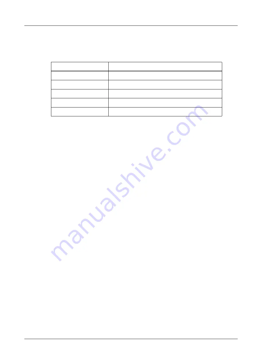
The delay times listed below must be followed to prevent the tube from overheating.

Tab. 4

Delay times between two exposures

Exposure mAs value

Delay time between two exposures (seconds)

max. 100

min. 15

max. 200

min. 30

max. 300

min. 45

max. 400

min. 60

max. 500

min. 75

Содержание MAMMOMAT Novation DR

Страница 1: ...ty Offenders will be liable for damages All rights including rights created by patent grant or registration of a utility model or design are reserved Print No U r d a n e t a MAMMOMAT Novation DR System Start up SP 2005 SPB7 250 815 06 02 02 Replaces SPB7 250 815 06 01 02 English Doc Gen Date 12 05 with WH AWS VA11C VA11D 08380490 ...

Страница 2: ...ce to order current revision levels Disclaimer The installation and service of equipment described herein is to be performed by qualified personnel who are employed by Siemens or one of its affiliates or who are otherwise authorized by Siemens or one of its affiliates to provide such services Assemblers and other persons who are not employed by or otherwise directly affiliated with or authorized b...

Страница 3: ...he oscilloscope 13 Service software 14 Delay times between two exposures 15 Rebooting the system 16 3 _______ Power up the MAMMOMAT_______________________________________ 17 Radiation protection door switch optional 17 External exposure lamp optional 18 Mains voltage 19 Electrical power to mains input 19 Connections 20 Measuring the line resistance 21 Start up of the MAMMOMAT system 21 4 _______ D...

Страница 4: ...limator 49 Collimator reference axis 49 Collimator beam check and calibration 50 8 _______ Checking dose settings__________________________________________ 55 Enable Disable Dose Calculation 55 Configuring of Dose Calculation System 55 Label 56 Checking OPDOSE 57 Checking the AEC dose settings 58 9 _______ Image Quality __________________________________________________ 63 Checking Grid Lines 63 P...

Страница 5: ...n 103 Collimator field light calibration 103 Collimator wing difference 103 AEC dose settings 103 OPDOSE settings 104 Check of grid lines 104 Display contrast and density of images 105 Activity report 105 General Remarks 106 12 ______ Appendix ____________________________________________________ 108 Troubleshooting image quality 108 Working with the service PC 112 Description of the syntax used in...

Страница 6: ... the MAMMOMAT NovationDR installation depends on the cus tomer s choice Fig 1 Configuration Unless otherwise stated these instructions describe the MAMMOMAT NovationDR Stand with the integrated generator radiation shield with the integrated control console detector and Acquisition Workstation WH AWS Depending on the installation configuration some points may be omitted ...

Страница 7: ... 87 97 02 101 97 03 976 No Service PC See the CS Intranet CS For Service Com mon Services Service Laptop for CSEs for details No Power line impedance meter 84 28 104 No Power ground wire tester 44 15 899 No Luminance meter for monitor cali bration e g Mavo Monitor or Wellhöfer LXplus 05 146 167 97 02 432 No Luminance meter measures the light intensity from the X ray field e g SMfit Mammo 88 81 281...

Страница 8: ...2 mm and one 0 5 mm sheets of aluminum 99 1100 alloy 4x4 cm 88 81 273 No Mammography line pair phantom 2 10 lp mm 88 81 299 No Collimator mounted plexi 4 cm Yes Compression plate simulator Yes 4 2 cm plexi Size of the detector 74 47 720 No Ethernet cable No Serial PC cable RS232 Array BRICK 66 55 745 Yes Serial PC cable RS232 Stand 99 00 440 No Cassette Film 24x30 cm No Centering cross 96 60 051 N...

Страница 9: ...5 CS SD 24 Important Notes 9 Page 9 of 116 Medical Solutions 3 2Important Notes Symbols 0 X This symbol indicates exposure to X ray radiation P This symbol indicates that the measured values have to be entered in the Startup Proto col on Start up Protocol p 97 ...

Страница 10: ...ted in the factory leav ing the adaptation to the on site mains voltage adjustment of the AEC and the functional tests to be performed When the measurements to be made kV mAs etc are within the tolerances stated in these instructions this confirms that the settings made in the factory have not changed and the equipment is fully serviceable The equipment is tested with 400 V 2 phase in the factory ...

Страница 11: ...n this Quality Control Manual SPB7 250 623 02 ensuring that a basic mini mum image quality criteria is met before the system is used with patients All yearly tests from the Quality Control Manual have to be performed Depending on the country where the system is installed additional tests have to be per formed Tests according to RöV 16 regulations must be performed in Germany Tests according to DHH...

Страница 12: ...tions presented here WARNING After the system shuts down there may still be 380 V DC present on the intermediate circuit A life threatening hazard of electric shock exists PC boards 0 CAUTION The printed circuit boards contain highly electrostatically sensi tive components If disregarded the components could be damaged Use ESD equipment ground prior to making contact and place the components on a ...

Страница 13: ...e protective strips when not in use are provided on both sides of the curtain Measurements with the oscilloscope 0 WARNING Under no circumstances should the existing ground conductor in the mains cable be disconnected when operating the oscilloscope There is a life threatening hazard of electric shock For measurements in which a resulting ground loop may affect the measuring result use the differe...

Страница 14: ...e Service PC is required for MAMMOMAT stand service software When the generator is switched off with the service PC connected wait approximately 5minutes before switching it on again The LEDs H3 and H4 have to be off A description of the various service software packages can be found in the MAMMOMAT NovationDR manuals for Software SPB7 250 816 NOTE When the generator is switched off with the servi...

Страница 15: ...ical Solutions Delay times between two exposures 0 The delay times listed below must be followed to prevent the tube from overheating Tab 4 Delay times between two exposures Exposure mAs value Delay time between two exposures seconds max 100 min 15 max 200 min 30 max 300 min 45 max 400 min 60 max 500 min 75 ...

Страница 16: ...Notes MAMMOMAT Novation DR SPB7 250 815 06 02 02 Siemens AG 12 05 CS SD 24 Page 16 of 116 Medical Solutions Rebooting the system 0 NOTE The system should be switched off completely once a week no power on the stand ...

Страница 17: ...otection door switch is not delivered with the MAM MOMAT NovationDR A 15V 5 mA signal is used in the door switch circuit When the signal path is opened by the door switch the exposure will immediately be terminated Fig 3 Connecting the door switch 1 To connect a door switch remove the jumper from the X754 Pin 1 2 located on the master board D750 see Fig 1 and connect the door switch instead If a r...

Страница 18: ...om the master board is only active during exposure thus the exposure lamp will only be lit when the signal is active Connect the cable to the lamp holder in series with the power supply CAUTION When connecting the exposure lamp to the master board make sure that the electrical load does not exceed 24VAC 25W 1 Connect the exposure lamp to the connector X759 located on the master board D750 see Fig ...

Страница 19: ... make sure that the cable plugs left and right of the system for the magnification table are not shorted The mains input can be either 1 phase or 2 phase 50 or 60 Hz Electrical power to mains input 0 Mains voltage 1 phase or 2 phase 208 230 240 and 277 V 10 208 230 240 277 and 400 V 10 Mains Frequency 50 or 60 Hz Maximum load 10kVA momentary and 0 8 kVA long time load Fuse 25 A external 208 400 V ...

Страница 20: ...train relieve the incoming mains cable Power system Type of connection Power voltage Power connections Single phase Phase to neutral 208 V 277 V Connect to 3 and 4 see No 1 Fig 5 p 20 Two phase Phase to phase 208 V 400 V phase to phase Note Max 277 V phase to neu tral ground allowed Connect to 3 and 4 see No 1 Fig 5 p 20 Use two phases of three in a nor mal power distribution sys tem The leftover ...

Страница 21: ...es 4 Press the power ON button on the control console to activate the MAMMOMAT Nova tion DR The internal monitoring system automatically performs a functional check of the MAMMOMAT Novation DR As a result dr is displayed on the film density display on the control panel to indicate that the communication with the MAMMOMAT Novation DR system is working properly when the detector wing is selected 5 S...

Страница 22: ...ontrol console After approximately 5 seconds check that the CPU IC107 status LED D13 is flashing rapidly and the LEDs D14 D15 and D16 are OFF 4 Check that LED D25 on the master board D750 is flashing slowly once per second Arranging the swivel arm 1 Remove the protective strips from the metal curtain 2 Run the lifting carriage upwards 3 Attach the protective strips back onto the metal curtain V1 F...

Страница 23: ...o 0 degrees by pressing one of the switches for clock wise rotation on the supporting arm 5 Unlock the wing and move the film wing to the park position Start up of the Acquisition Workstation System specific data has to be entered and set The start up and configuration of the acquisition workstation is described in the document Start up WH AWS SPB7 250 815 02 ...

Страница 24: ...ge 24 of 116 Medical Solutions 5 4Detector installation Unpacking of the detector 0 Fig 6 Opening the cardboard box 1 Open the cardboard boxes and remove the top packing insert Fig 7 Opening the box 2 Remove all of the other packing material covering the inner box in which the detector is located ...

Страница 25: ... Fig 9 Remove packing material 4 Slide the lifting band from the inner box 5 Lift out the detector and carefully remove from wrapper 6 Open box remove packing insert temperature logger and phase change material 7 Remove the packing material inside the inner box which includes the temperature log ger that is used to ensure that the detector maintained the proper temperature while be ing shipped and...

Страница 26: ...mately 25 mm inside the other three edges 9 Check the temperature logger with a ball pen as shown in Fig 10 p 26 Fig 10 Check temperature logger NOTE A green LED indicates that the transportation was OK and the de tector can be installed A red LED indicates that the detector is defective and has to be re placed NOTE You have to send the temperature logger to the factory using the regular Customer ...

Страница 27: ...ctor is correctly mounted and that it is lo cated directly below the radiation field use the guiding lines on the wing and make sure that the detector is in the right position before screwing the bolts 5 Insert the detector cable underneath the grid holder and tighten the grid holder screws again 4 Fig 11 p 27 6 Connect the detector cable 3 Fig 11 p 27 to the cable coming out of the wing 2 Fig 11 ...

Страница 28: ...ble 4 Line up the grid so that it runs parallel to the front of the table the front switch has to be engaged and the grid sliders have to be engaged with the spring 6 Fig 12 p 28 NOTE Make sure that the grid sliders are locked in place and have only little play Make sure the springs move up and down easily 5 Mount and dismount the MAG table several times and check if both grid holders 1 Fig 12 p 2...

Страница 29: ... 06 02 02 MAMMOMAT Novation DR 12 05 CS SD 24 Detector installation 29 Page 29 of 116 Medical Solutions WARNING Fire hazard If not observed the D805 will burn up Make sure that the cables are connected according to the labels ...

Страница 30: ...to the front S2 must switch 2 mm 1 mm tolerance before the grid reaches the end position 3 Adjustment of S3 Move the grid to the back and insert the magnification table S3 must switch 2 mm 1 mm tolerance before the magnification table reaches the end position NOTE The magnification table is optional When no magnification is supplied with the system the micro switch has to be mounted along the mark...

Страница 31: ...tor installation 31 Page 31 of 116 Medical Solutions Mounting the covers 0 1 Mount the top wing cover with 4 screws 2 Slide the detector fiber cover carefully over the detector and fasten it with 6 screws at the bottom of the cover 3 Mount the bottom wing cover with 6 screws ...

Страница 32: ... not already done mount the cable duct covers Swivel arm covers 0 Fig 14 Connecting the cables Before installing the side covers the cables have to be connected 1 Connect cables X807 1 Fig 14 p 32 to control button circuit boards D807 2 Fig 14 p 32 2 Connect ground wires 3 Fig 14 p 32 to patient handles 4 Fig 14 p 32 Side cover 0 Screws in different sizes are included in the delivery ...

Страница 33: ...rews are not used at the back of the covers at the upper location since this may damage the board un derneath the cover see 6 Fig 15 p 33 Front cover 0 CAUTION Risk of damages If the covers are exposed to internal stress cracks might arise The following work must be carried out with caution 1 The side covers must be flush at the front If necessary loosen the screws and adjust the side covers 2 Car...

Страница 34: ...mounted Store the strips in the holders pro vided on both sides of the curtain NOTE When mounting the stand covers make sure that the screws at the top of the stand are securely tightened and have functioning con tact washers These screws are used to establish protective ground connec tions Fig 16 Mounting the stand covers 1 The covers are delivered with a protective plastic film which should be r...

Страница 35: ... 5 Fig 16 p 34 and contact washers see 6 Fig 16 p 34 NOTE Be careful not to damage the cables at the cable outlet 5 Fit the inner plastic strip see 7 Fig 16 p 34 to the front and side covers and fasten with screws see 1 Fig 16 p 34 eight on either side 6 Press on the outer plastic strip 8 Fig 16 p 34 Stand cap Fig 17 Stand cap 1 Place the stand cap on the top of the MAMMOMAT stand see 2 Fig 17 p 3...

Страница 36: ...12 05 CS SD 24 Page 36 of 116 Medical Solutions Face shield 0 Fig 18 face_shield 1 Slide the face shield 1 Fig 18 p 36 onto the holder for external diaphragms Check ing the swivel arm system Mechanical Checks 0 Rotary motion The rotary motion has to be checked with both wings ...

Страница 37: ...al Solutions 1 System OFF The rotary motion and the vertical adjustment of the swivel arm system should be blocked Fig 19 swivel_arm_system 2 Turn the system ON 3 Select the detector wing dr is then displayed on the control console 4 Set the projection angle set to minimum with the presetting knob 1 Fig 19 p 37 ...

Страница 38: ...he buttons 2 Fig 19 p 37 The rotary motion of the swivel arm system should stop automatically when the preset projection angle both and is reached and at 0 degrees 90 degrees or 90 degrees NOTE All eight rotary motion buttons four on either side must be checked 2 Fig 19 p 37 After the button has been released the swivel arm system should remain in the position set OPDIMA wing 1 Select the OPDIMA w...

Страница 39: ...e buttons for upward and downward movement 3 Fig 19 p 37 of the swiv el arm system The movement should stop automatically when either the end position is reached or when the button is released NOTE All eight vertical adjustment buttons four on either side 3 Fig 19 p 37 must be checked The switching off in upper and lower end position is effected by switches S881 and S884 respectively Emergency sto...

Страница 40: ...t should go out automatically after a preset period of time normally 20 s Fig 22 Footswitch Adjusting the field light time The illumination time of the light field can be adjusted within a certain range according to the customer s requirements NOTE A shorter illumination time results in an increased lifetime of the lamp 1 Connect the service PC to the D750 and start the MAMMOMAT Service Software 2...

Страница 41: ...1 3 Check the function of the knobs for manual compression decompression 3 Fig 23 p 41 4 Place a piece of soft material on the object table for example a rolled up towel or a piece of foam rubber 4 Fig 23 p 41 5 Check the function of the foot switch for motorized compression decompression 1 2 Fig 24 p 41 Fig 24 Foot switch_2 6 Press the foot switch for motorized decompression to move the compressi...

Страница 42: ... opposite direction by hand The compression plate should now slow down and stop when the preset compression force is reached NOTE During compression the motorized vertical adjustment and the ro tary motion of the swivel arm system should be blocked Decompression button 0 Checking the OPCOMP 0 1 Decompress 2 Set the compression force to 20 kg by using the presetting knob 5 Fig 23 p 41 and compress ...

Страница 43: ...mpression force and vice versa Increase decrease the tautness factor by e g 10 the first time Let the customer use this setting for at least two weeks before further changes are made NOTE OPCOMP has been thoroughly tested by Siemens If any factors are changed OPCOMP will no longer be an optimization of com pression force and image quality according to Siemens clinical test Checking the exposure bl...

Страница 44: ...ect the service PC to the stand Switch the system ON Start the Service Program and check in the anode menu whether the tungsten anode is enabled Measurement method 0 The mAs value must be calculated as the product of the tube current and exposure time The tube current and the exposure time can be obtained from the oscillograms The diagram may have glitches in which case you have to measure the exp...

Страница 45: ... diagram_30kV_20mAs_Mo_Mo Fig 29 diagram_30kV_20mAs_W_Rh 30 kV 1 V T 1 T 5 kV 30 kV 1 V T 1 T 5 kV 130 mA 1 V T 1 T 40 mA 166 mA 1 V T 1 T 40 mA 160 ms 20 ms T 128 ms 20 ms T Fig 30 diagram_30kV_100mAs_Mo_Mo Fig 31 diagram_30kV_100mAs_W_Rh 30 kV 1 V T 1 T 5 kV 30 kV 1 V T 1 T 5 kV 112 mA 1 V T 1 T 40 mA 132 mA 1 V T 1 T 40 mA 0 9 sec 0 2 s T 0 72 sec 0 2 s T ...

Страница 46: ...gain cali bration at this point You may only then continue with these mea surements For more details on how to perform the gain calibration see Gain calibration on Gain calibration p 72 2 Adjust the exposure value on the control console according to the table above X 3 Start an exposure 4 Check and measure the kV value and the tube current characteristic on the oscillo scope The accuracy of the kV...

Страница 47: ...e The accuracy of the kV is 5 for tube current 10 and for the mAs product 10 P 4 Record the measured kV and mAs value in the Start up Protocol on Start up Protocol p 97 5 Change the setting and continue with the next measurement until you have completed all measurements from the table above Checks with a large focus and with AEC 0 NOTE Be aware that with the AEC mode on a pre exposure of 50 ms is ...

Страница 48: ...above X 2 Start an exposure 3 Check and measure the kV value and the tube current characteristic on the oscillo scope The accuracy of the kV is 5 for tube current 10 and for the mAs product 10 P 4 Record the measured kV and mAs value in the Start up Protocol on Start up Protocol p 97 5 Change the setting and continue with the next measurement until you have completed all measurements from the tabl...

Страница 49: ...light bulb i e to get the illumination field This field will correspond to the radiation field during the exposure When the exposure preparation is started the col limator lamellae are adjusted to the currently selected anode focus i e to get the radiation field Exposure will not be allowed as long as collimation is not ready or an invalid object table and compression paddle combination has been s...

Страница 50: ...tart an exposure 7 View the image with a magnification of 4 8 Slide the magnification glass along the image edges of the image and check if white lines are visible NOTE If you do not see white lines at the edges of the image the collima tor beam calibration is correct and you can continue with the Col limator field light calibration on Collimator field light calibration p 52 Otherwise continue wit...

Страница 51: ...alues by 5 numbers 7 Select a focus anode combination 8 Make sure a patient is registered and start an exposure 9 Use a magnification of 4 in the application software and go to the edges of the detector White areas should be visible at all edges of the image This shows you that the X ray does not cover the entire detector and shows where the beam really ends 10 Measure the white line thickness at ...

Страница 52: ...he field light is carried out as follows 1 Select the detector wing dr is then displayed on the control console 2 Start the service software on the service PC and select Configuration Collimator Calibration of light field Fig 34 Collimator light calibration 3 Position the X ray cross in the center of the detector 4 Make sure that a patient is registered 5 Mount the Collimator Mounted Phantom 6 Mou...

Страница 53: ...t the OPDIMA wing by moving the detector into the park position OP is then dis played on the control console 2 Connect the compression plate simulator and the collimator mounted plexi phantom 3 Start the service software on the service PC and select Configuration Collimator Calibration of wing difference Fig 35 Collimator wing difference calibration 4 Enter the numbers in the table below Tab 11 Wi...

Страница 54: ... edge with the application graphical user interface and adjust the corresponding XL XR YC and YS values with the service software X 9 Start an exposure 10 Check if the white lines at the edges of the image are gone using a magnification of 4 in the application graphical user interface 11 Save the calibration and Exit from the Service Software NOTE If you see a white thin line on the chest wall whe...

Страница 55: ...will still be performed and can be printed out if the printer option is installed Configuring of Dose Calculation System 0 The Dose Calculation System comes with factory default values The factory default val ues should typically be used If desired measurements of HVL Half Value Layer and dose exchange factors can be performed to improve the accuracy of displayed dose val ues These measurements sh...

Страница 56: ...06 02 02 Siemens AG 12 05 CS SD 24 Page 56 of 116 Medical Solutions Label 0 If the Dose Calculation System is enabled affix a mAs mGy label over the mAs text on the control and display panel The label is found in tab 3 of the Technical Manual binder Fig 37 Label ...

Страница 57: ...t is within the thickness in terval of the program to be tested 4 Select AUTO on the control panel 5 Place the calibration plexi on the object table and compress to 6 kg or more 6 Check that the correct program is blinking on the control panel Select the program by pressing the corresponding program button on the control panel 7 Repeat the procedure described in steps 3 6 for the other programs us...

Страница 58: ...console have to be checked As a default from the factory the following BRICK AEC Configuration values are set for further details see the Software Brick V manual SPB7 250 816 04 H 80 70 45 D 100 80 60 Checking the H D dose settings for Mo Mo Proceed as follows 1 Mount the collimator mounted plexi phantom and the compression plate simulator 2 Register or create a patient and submit with Exam Fig 38...

Страница 59: ...iate exposure parameters according to the table Tab 12 Checking H D dose settings for Mo Mo 5 Position the dose meter probe 6 cm from the chest wall and 3 cm off the center of the detector NOTE If parts of the meter probe cover the AEC sensor one will get a higher dose Thus make sure that the probe is not covering the AEC sensors This can be checked with the mounted compression plate The AEC senso...

Страница 60: ...col p 97 Check the H D dose settings for Mo Rh and W Rh If the Mo Mo AEC dose values for H D are within the specification proceed as follows 1 Mount the collimator mounted plexi phantom X 2 Select the appropriate exposure parameters according to the table and start an expo sure 3 Select the anode filter combination according to the table and set the mAs control con sole as close as possible to the...

Страница 61: ... enter the correct values and select save then use load to load them before you start another exposure Calculation of the new Mo Mo dose scaling value Calculation of the new Mo Rh W Rh dose scaling values Proceed as follows 1 Call up the service software and select Acquisition System BRICK Configuration The BRICK service software opens another window 2 Select Brick AEC Configuration 3 The BRICK so...

Страница 62: ...he default values are 80 70 45 and enter the new values separated by a comma e g 80 70 45 in the Low Dose Scaling Value field and click Change Low Dose Scaling to save it D value go to Modify high dose scaling The default values are 100 80 60 and enter the new values separated by a comma e g 100 80 60 in the High Dose Scaling Value field and click Change High Dose Scaling to save it 6 Proceed from...

Страница 63: ...grid lines are visible in one or more images the grade of grid lines must be measured The criteria for the mean pixel value difference of the visible grid lines is less than 1 3 Eliminating Grid lines on Eliminating grid lines p 66 Preconditions 0 The system is up and running The operator is logged in to the system The compression plate simulator is mounted on the MAMMOMAT Checking visibility of g...

Страница 64: ... 28 kV and Mo Mo 4 Make sure that a 1 1 view is selected to have a better view Select View a 1 1 5 Make all exposures according to Tab 1 6 Activate magnification Image Magnify by 2 0 and look for grid lines over the plexi phantom area 7 Make a not of the results visible grid lines in Tab 1 choose the next image in the list and start over with step 5 until all images are evaluated Test 1 protocol 0...

Страница 65: ...s 0 1 Load the image in the syngo Image Viewer and select the first image where visible grid lines were detected see Checking visibility of grid lines p 63 To do so click the Viewing tab card load the image with the Patient Browser and select Tools Rectangle 2 Activate magnification Image Magnify by 2 0 3 Select Tools Rectangle and draw a rectangle approx 1 sq cm on the back ground as shown in X F...

Страница 66: ...uring Grid Lines Test Criteria If the mean pixel value difference is less than 1 for the images with visible grid lines the test has passed If the mean pixel value difference does not meet the criteria continue with Eliminating Grid lines on Eliminating grid lines p 66 Otherwise P Record the measured value in the Start up Protocol on Start up Protocol p 97 and continue with Checking Image Quality ...

Страница 67: ...rning point The switch must be correctly adjusted otherwise the high voltage will be active when the grid is standing still To minimize this risk of the high voltage being active when the grid is standing still the high voltage should be disabled for as long as possible 1 Move the grid to the left end position 2 Loosen the three screws Now it s possible to adjust the grid switch S1 alongside the g...

Страница 68: ...lits see Fig 45 p 68 and Fig 46 p 68 You ll hear a click when the switch activates or deactivates Fig 45 Adjust grid switch on edge 1 Fig 46 Adjust grid switch on edge 2 4 Tighten the three screws 5 Move the grid to the other end position and check that the grid switch activates deacti vates on either edge of the slit see Fig 46 p 68 and Fig 45 p 68 Adjusting the wheel that is mounted on the grid ...

Страница 69: ... not horizontal loosen the screw on the wheel and adjust it so that the slits are horizontal in both end positions Adjusting the grid location 1 Open the carbon detector cover 2 Make sure the grid is mounted parallel to the detector and is lined up with the front of the table The front switch has to be engaged and the springs for the grid holders left and right have to be engaged see Mounting the ...

Страница 70: ... the service software Main menu Configuration Grid speed 2 Set the parameter as shown in Fig 49 p 70 Fig 49 Adjusting the grid motor speed 3 Check the grid speed with the oscilloscope The grid speed can be measured with the oscilloscope See also Mammomat Novation System Start up SPB7 250 815 chapter X Ray tube checks for systems with WH AWS Measurement Switch the system OFF ...

Страница 71: ...id lines are still visible after this process increase i e change the grid slow speed from 40 to 50 and run this test again Checking Image Quality 0 While calibration is typically performed by the customer as part of normal system opera tion calibration information is provided in the event that you are required to perform a sys tem calibration To calibrate the system proceed as follows First perfo...

Страница 72: ...ferences along with other variables that can affect the digital signal output The system can then apply adjust ments to the output data to compensate for these differences When is it necessary to perform the gain calibration of the detector The gain calibration of the detector must be performed every two weeks a pop up draws the user s attention to this Once a week is recom mended NOTE Perform the...

Страница 73: ...T Novation DR 12 05 CS SD 24 Image Quality 73 Page 73 of 116 Medical Solutions 2 Select Patient Calibration from the syngo menu bar Fig 51 Select_calibration 3 Click the Gain button to start the calibration 4 Confirm the message that pops up ...

Страница 74: ...rm the calibration with W Rh 7 Insert the collimator mounted plexi phantom 8 Mount the compression plate simulator 9 Double click the first Image of Procedure Calibration X 10 Start an exposure Wait until the image is loaded into the viewer The following lines are displayed in the message bar Image acquisition is in progress Saving processed Image Loading Image 11 Check the image quality of the im...

Страница 75: ... of 116 Medical Solutions NOTE It is recommended to reject an image if it shows any cut off edges due to collimation or misalignment or if there are any artifacts from debris or obstructions Example images of a calibration Fig 53 Gain calibration_good example Fig 54 Gain calibration_bad example ...

Страница 76: ... if necessary 0 During the calibration function you have the option of creating a new pixel map of the detector The pixel map indicates which pixels in the detector s array might not be reading X ray densities correctly and therefore should be ignored when the image is acquired This is similar to a bad spot map for a computer s hard disk A new pixel map should be created when an excessive amount o...

Страница 77: ...05 CS SD 24 Image Quality 77 Page 77 of 116 Medical Solutions 3 As a result the following screen is displayed Fig 56 Acquisition System Menu 4 Select the Examination tab card NOTE Make sure that no patient is registered before you start the bad pix el mapping ...

Страница 78: ...250 815 06 02 02 Siemens AG 12 05 CS SD 24 Page 78 of 116 Medical Solutions 5 Select Patient Calibration from the syngo menu bar Fig 57 Calibration 6 Click on the Bad pixel button to start the bad pixel mapping 7 Confirm the message that pops up ...

Страница 79: ...Wait until the image is loaded into the viewer The following lines are displayed in the message bar Image acquisition is in progress Saving processes Image Loading image 14 Click the Accept or Reject button If you accept the image the new pixel map is created When the Accept images counter increases to 1 no further images need to be taken If you reject the image the Bad Pixel Mapping menu is displ...

Страница 80: ...he first installation of the system You need the HVL for the Mean glandular dose test and you can find them in the technical documentation binder in the Röntgenprotokoll X ray protocol Other issues You ll find the Quality Control documentation in the Instructions for Use binder It is shipped with the system The Quality Control Manual that corresponds to the location of the installation has to be u...

Страница 81: ...ges are not loaded by the system proceed as follows Prerequisites Click the Resources Monitor icon disk space indicator in the bottom right corner of the syngo screen to check this The free storage space is shown under the Local Blob Blob Binary Large Object Free entry 1 Load the images by opening the syngo Patient Browser 2 Select the cdr icon 3 Select the desired data objects 4 Click the Import ...

Страница 82: ...administrator Enter the correct password 3 A command window will open granting you administrator rights provided that you are logged in as administrator 4 Enter notepad C AWS config LoradIP AwsIpmParamDefault_Lorad ini and press Return or Enter A TXT file is called up In approximately in the 10th and 11th line you can find the values for DisplayDensity and the DisplayContrast 5 Change the settings...

Страница 83: ...re descriptions see the table Description of Image Processing Parameters For these settings select Local service Acquisition system General settings Image processing see Fig 59 p 83 The default processing parameter groups cannot be overwritten For a customer s personal settings a new group e g Standard has to be created Fig 59 Image processing parameters Description of Image Processing Parameters ...

Страница 84: ...n 0 3 Gain value for enhancement of the local contrast Do not change Edge Enhancement Kernel 15 Do not change Edge Enhancement LUT index 0 Currently not used future plan to have different edge enhancement based on mean gray value in image Do not change LUT index 18 Separate LUTs to calculate the dis played values are delivered Do not change Harmonization Ampli fication Gain 0 7 Gain value for enha...

Страница 85: ... used if exami nations of these types are performed In case the image processing fails completely using Reprocessing with the safety setting should correct this problem Window Center Shift 150 Defines center of gray values to be displayed Decrease if image should be brighter Increase if image should be darker 3 predefined settings exist Normal Low High Implant Recognition Mode ON Defines whether i...

Страница 86: ...Enhance ment Kernel 15 15 15 15 15 15 15 15 Edge Enhance ment LUT index 0 0 0 0 0 0 0 0 LUT index 18 18 18 18 20 6 6 6 Harmoniza tion Amplifi cation Gain 0 7 0 7 0 7 0 7 0 6 0 2 0 0 6 Harmoniza tion Kernel Size 127 127 127 127 127 127 127 127 Factor make window width wider 1 6 1 4 1 8 2 0 1 5 2 0 2 0 1 6 Window Center Shift 150 120 180 50 140 0 0 150 Implant Rec ognition Mode ON ON ON ON ON OFF ON...

Страница 87: ...omer wants to adjust the basic settings for brightness and con trast the images must be windowed according to the customer s preferences based on an IPPG setting New values for window width and window center can be determined using the image processing configurator The values set by the customer as the optimal ones are en tered in the configurator whereupon the average values are determined The ne...

Страница 88: ... contrast and the brightness e g Normal and change the name to e g Standard 8 Change the parameter Window Center Shift and Factor make window width wider to the new values displayed in the configuration tool and save the PPG The new calculated values for Factor make window width wider and Window Center Shift have to be entered in the corresponding fields Tab 16 Settings for normal parameters Defau...

Страница 89: ...tions 11 10Final procedures Disabling the film exposure 0 The film exposure switch has to be disabled 1 Connect the service PC to the MAMMOMAT stand and start the service software 2 Go to Configuration Miscellaneous Allow film exposure and make sure that the Switch is set to OFF Fig 60 Set Allow film exposure to OFF ...

Страница 90: ...ping time ENTER Test performance 1 Start the Service Software for the MAMMOMAT Stand on the Service PC 2 In the Main menu select Configuration Clock Fig 61 MAMMOMAT Stand clock adjustment 3 Press F2 With F2 the date and time set in the service PC are taken over by the MAMMOMAT stand BRICK 0 1 Call up the WH AWS service software and select Utilities Escape to OS Enter then the following command in ...

Страница 91: ...ons 3 To check the current date and time setting on the BRICK use the following command brick date To set the date and time on the BRICK use the following command brick date mmddHHMMyy mm month dd day HH hours MM minutes yy year The following example sets the system to 3 10 p m on November 21 2004 brick date 1121031004 ...

Страница 92: ...ta Reset the exposure counter Main menu 1 Select Service Reset exposure counter 2 Delete the error memory with Y Deleting the error buffer Main menu 1 Select Service Delete error buffer 2 Delete the error memory with Y Saving the MAMMOMAT Parameters Main menu 1 Select Backup Copy Installation Area to Floppy Stand 2 Select Backup Copy Installation Area to Floppy Panel 3 Exit the program with F10 wh...

Страница 93: ...5 06 02 02 MAMMOMAT Novation DR 12 05 CS SD 24 Final procedures 93 Page 93 of 116 Medical Solutions Remove the measuring instruments 0 1 Turn OFF the MAMMOMAT 2 Remove the service PC 3 Remove connected measuring instruments ...

Страница 94: ...otective grounding resistance 0 Using the protective ground wire tester measure the resistance between the protective ground terminal in the stand Mains input terminal and all metallic parts of the equipment which the patient operator may come in contact with incl all object tables The protective ground resistance must not exceed 0 1 Ohm ...

Страница 95: ...h Italian Dutch Danish Norwegian Finnish Greek and Swedish The warning labels are found in a plastic bag under thumb index 3 in the Technical Manual NOTE A warning label in English is provided on delivery Choose the appropriate language and affix the label over the existing label on the control panel see Fig 62 p 95 Be sure to position the label properly before affixing it The label sticks immedia...

Страница 96: ...cessary that the installation Protocol with the installation and start up data is sent without delay after completion of the work to the address stated on the installation protocol The SP Q Installation Protocol has to be filled in and signed The form can be found in chapter 9 Certificates of the technical documentation binder Appendix of 66 46 900 QZE 01S xx It has to be sent to the address state...

Страница 97: ...______ System Ser No ______________ Customer _____________________________________________________ Country city _____________________________________________________ Installation team _____________________________________________________ Project manager _____________________________________________________ Installation start ____________________ Installation end ______________ ...

Страница 98: ...uxiliary materials Item Model Calibration date Serial number Oscilloscope 50MHz with memory Digital multimeter including an mAs meter Power line impedance meter Power ground wire tester Luminance meter for monitor calibration Luminance meter measures the light intensity from the X ray field Dose meter Ion chamber Densitometer A non invasive digital kV meter ...

Страница 99: ...4 Start up Protocol 99 Page 99 of 116 Medical Solutions Installation and start up steps performed 0 Work per formed Yes No Installation The MAMMOMAT NovationDR was installed completely All covers are mounted The temperature logger was sent to DirectRay Cooperation DRC ...

Страница 100: ...X Ray tube checks performed Collimator checks performed Dose settings checked Acquisition workstation configurations performed Configured DICOM services Image quality tests performed Acceptance tests performed Ground wire tested Line resistance tested Backup for acquisition workstation and MAMMOMAT created SP Q Quality Certificate filled in and sent when problems occurred with either the Installat...

Страница 101: ... DR 12 05 CS SD 24 Start up Protocol 101 Page 101 of 116 Medical Solutions Startup Settings 0 Tube high voltage current and mAs values 0 Results from the chapter Tube high voltage current and mAs values on Tube high volt age current and mAs values p 44 ...

Страница 102: ...102 Start up Protocol MAMMOMAT Novation DR SPB7 250 815 06 02 02 Siemens AG 12 05 CS SD 24 Page 102 of 116 Medical Solutions Fig 63 Start up Settings ...

Страница 103: ...imator field light calibration on Collimator field light calibration p 52 Tab 19 Collimator field light calibration Collimator wing difference 0 Results from the chapter Collimator Wing Difference Calibration on Collimator Wing Dif ference Calibration p 53 Tab 20 Wing difference AEC dose settings 0 Results from the chapter Checking the AEC dose settings on Checking the AEC dose settings p 58 Focus...

Страница 104: ... Check of grid lines 0 Results from the chapter Checking Grid Lines on Checking Grid Lines p 63 Tab 23 Measuring Grid Lines AEC kV Anode Filter Dose value Pixel value H 28 kV Mo Mo D H Mo Rh D H W Rh D Program button Thickness kV Anode filter combination AEC 1 2 3 4 Exposure Exp Mode mAs PMMA mm Tube Angle visible grid lines yes no X Y Mean pixel value differ ence 1 mAs 32 30 0o 2 mAs 56 40 0o 3 m...

Страница 105: ...and Density Settings Activity report 0 Default Result Factor make window width wider 1 6 Window Center Shift 150 Day Start End E M V R KA Work performed Employees number Total Mh Explanation of the activity report Day Start End Date start of work end of work time E Bringing in the entire system in hours per day M Installation of the entire system in hours per day V Cabling of the system in hours p...

Страница 106: ..._______________________________ _____________________________________________________________________ _____________________________________________________________________ _____________________________________________________________________ _____________________________________________________________________ _____________________________________________________________________ __________________...

Страница 107: ... Page 107 of 116 Medical Solutions _________________ _____________________ __________________________ Place date Installation team employee Siemens project manager person responsible for the project ______________________ __________________________ Name in block letters Name in block letters ...

Страница 108: ...e component that is producing it First similar appearing artifacts can come from anywhere in the overall image chain Second the tendency to assume that the artifact is coming from the least known component must be avoided For example artifacts that appear to be coming from the detector may actu ally be coming from the output device or processing Isolation is the first step and should be done by us...

Страница 109: ...ibration pro cedure refer to Gain calibration on Gain calibration p 72 Perform the bad pixel correction Refer to Creation of new pixel map on Creation of a new pixel map if necessary p 76 Line Parallel to the Long Axis Line ends at seam or line partially defective gate lines Line ends at seam or line partially defective gate lines Detector not calibrated properly line needs to be mapped out Perfor...

Страница 110: ...aring in one or more quar ters of Detector Detector defective Detector might have to be replaced contact the Service Center Garbled scrambled or truncated from edges of long axis in images not appearing in one or more quar ters of Detector Poor cable connection Electronic interference with or along cable Check pins and Detector connec tion to PXCM Identify and isolate sources of inter ference exam...

Страница 111: ... Solutions Poor image quality Detector not calibrated to optimal operating temperature Allow proper warmup time to normal operational temperature Distorted image with 256 blocks Detector defective Detector might have to be replaced contact the Service Center Other Artifacts Problem Cause Recommended Action ...

Страница 112: ...icates that at this point the space key must be pressed xx yy zz Data can be entered in place of x y z e g day s date Curved brackets indicate that one item must be selected from a list of several terms Important remarks are indicated by this box When the password is entered only these characters are shown Menu Selection When several menus programs files etc are presented for selection they are sh...

Страница 113: ...igned to ensure general compatibility with the OS s Win dows 2000 Pro on modern PC s If the settings are saved this procedure has to be done only once Configuring the computer BIOS 0 1 Enter the BIOS setup usually done by pressing e g F2 during the boot sequence of the BIOS 2 Find the configuration of the IrDA Infrared device port and disable it 3 Find the configuration of a built in modem and mak...

Страница 114: ...ension c if you have a color dis play then press ENTER The program asks for the user s name Your name please Type the name of the technician for example NN and then press ENTER 5 The program asks for the password Password please Type the password and then press ENTER The display window shows Main menu 6 Select the program part to be used with keys and or then press ENTER The selected program part ...

Страница 115: ...115 of 116 Medical Solutions 4 Choose the tab Hardware 5 Press the button Device Manager 6 Expand the row Ports 7 Double click on the COM1 row 8 Choose the tab Port Settings 9 Press the button Advanced 10 Uncheck the check box Use FIFO Buffers 11 Exit the dialog by pressing the OK button ...

Страница 116: ... 815 06 02 02 Siemens AG 12 05 CS SD 24 Page 116 of 116 Medical Solutions 14 13Changes to the previous version Chapter Page Change Checking dose set tings 55 Source of Configuring of Dose Calculation adapted Final work steps 92 Saving the Mammomat Parameters adapted ...

Отзывы: