


LMV Series
Technical Instructions
LV5-1000
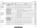
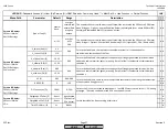
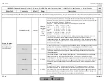
Menu Path
Parameter
Default
Range
Description
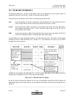
51.1
52.2
52.4
LEGEND -
Password Access:
(U)=User, (S)=Service, (O)=OEM, Shaded = Commonly Used, ** = Must Set, X = Has Function, / = Partial Function
LMV
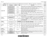
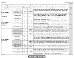
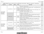
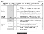
HeavyOilDirStart (O)
38/44..62
38/44..62
act 21..62
HTempGuard
ext.FlameGd
deactivated
activ 38/44
Sets the function of INPUT X6-01.3.
1) 38/44..62 - input must be energized in phase 38 and / or 44, and during phases 50 thru 62.
2) act 21..62 - input must be energized for phase 21 thru 62. This setting is useful for a low
oil temperature switch.
3) HTempGuard - only used on an LMV50.
4) ext.FlameGd - input is used for a flame signal from an external flame safeguard. If used,
no flame detector may be connected to terminal X10.
5) deactivated - terminal has no function.
6) activ 38/44 - input must be energized in phase 38 or 44.
/ / /
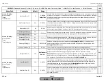
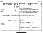
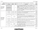
Start/PS-Valve (S)
Start Signal
StartSignal
PS Relief
PS Reli_Inv
Sets the function of OUTPUT X4-03.3.
1) StartSignal - output is energized from phase 21 (before the blower) thru phase 78 (after
postpurge), and is suited to open an outside air or stack damper. If ContinuousPurge is
activated, this terminal will be energized with the fan.
2) PS Relief - wired to a 3-way valve used to check the action of combustion air pressure
switch and is necessary if direct start is used. Energizing vents the combustion air pressure
switch to atmosphere during phase 79.
3) PS Reli_Inv - the action is opposite of PS Relief mode, thus de-energizing vents the
combustion air pressure switch to atmosphere during phase 79, and the 3-way valve is
energized during operation.
x x x
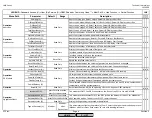
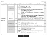
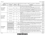
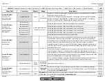
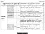
ReacExtranLight (S)
Startblock
Startblock
Lockout
If the extraneous light test is activated (see next parameter), this setting determines the
response to extraneous light.
1) Startblock - will not permit a start of the lightoff sequence.
2) Lockout - lockout in response to extraneous light.
ExtranLightTest (O)
activated
activated
deactivated
Activates or deactivates the extraneous light check during the start sequence and during
standby. NOTE : This setting is intended to be used with applications such as waste
incinerators. DO NOT deactivate for boiler burners.
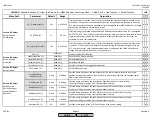
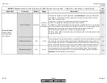
ReacTmeLossFlame (O)
0.2s
0.2-3.2s
Sets the flame failure reaction time. The LMV5 has a base flame failure reaction time of
approximately 0.8 seconds, so the setting of this parameter will add to the base flame failure
reaction time. Max total flame failure reaction time is 4 sec.
x x x
Params & Display>
BurnerControl>
Configuration>
ConfigIn/Output
Params & Display>
BurnerControl>
Configuration>
ConfigFlameDet
SCC Inc.
Page 14
Section 3
HOME
HOME
P - LIST
Содержание LMV 5 Series
Страница 2: ...Intentionally Left Blank ...
Страница 25: ...LMV Series Technical Instructions Document No LV5 1000 SCC Inc Page 21 Section 1 Intentionally Left Blank HOME ...
Страница 27: ...LMV Series Technical Instructions Document No LV5 1000 SCC Inc Page 23 Section 1 Intentionally Left Blank HOME ...
Страница 41: ...LMV Series Technical Instructions Document No LV5 1000 SCC Inc Page 7 Section 2 HOME ...
Страница 42: ...Technical Instructions LMV Series Document No LV5 1000 Section 2 Page 8 SCC Inc HOME ...
Страница 43: ...LMV Series Technical Instructions Document No LV5 1000 SCC Inc Page 9 Section 2 HOME ...
Страница 44: ...Technical Instructions LMV Series Document No LV5 1000 Section 2 Page 10 SCC Inc HOME ...
Страница 45: ...LMV Series Technical Instructions Document No LV5 1000 SCC Inc Page 11 Section 2 HOME ...
Страница 46: ...Technical Instructions LMV Series Document No LV5 1000 Section 2 Page 12 SCC Inc HOME ...
Страница 47: ...LMV Series Technical Instructions Document No LV5 1000 SCC Inc Page 13 Section 2 HOME ...
Страница 48: ...Technical Instructions LMV Series Document No LV5 1000 Section 2 Page 14 SCC Inc HOME ...
Страница 49: ...LMV Series Technical Instructions Document No LV5 1000 SCC Inc Page 15 Section 2 HOME ...
Страница 50: ...Technical Instructions LMV Series Document No LV5 1000 Section 2 Page 16 SCC Inc HOME ...
Страница 51: ...LMV Series Technical Instructions Document No LV5 1000 SCC Inc Page 17 Section 2 HOME ...
Страница 52: ...Technical Instructions LMV Series Document No LV5 1000 Section 2 Page 18 SCC Inc HOME ...
Страница 53: ...LMV Series Technical Instructions Document No LV5 1000 SCC Inc Page 19 Section 2 HOME ...
Страница 54: ...Technical Instructions LMV Series Document No LV5 1000 Section 2 Page 20 SCC Inc HOME ...
Страница 55: ...LMV Series Technical Instructions Document No LV5 1000 SCC Inc Page 21 Section 2 HOME ...
Страница 56: ...Technical Instructions LMV Series Document No LV5 1000 Section 2 Page 22 SCC Inc Intentionally Left Blank HOME ...
Страница 116: ...Technical Instructions LMV Series Document No LV5 1000 Section 3 Page 58 SCC Inc Intentionally Left Blank HOME ...
Страница 150: ...Technical Instructions LMV Series Document No LV5 1000 Section 4 Page 32 SCC Inc Intentionally Left Blank HOME ...
Страница 170: ...Technical Instructions LMV Series Document No LV5 1000 Section 5 Page 18 SCC Inc Intentionally Left Blank HOME ...
Страница 290: ...Technical Instructions LMV Series Document No LV5 1000 Section 8 Page 20 SCC Inc Intentionally Left Blank HOME ...
Страница 306: ...Technical Instructions LMV Series Document No LV5 1000 Section 9 Page 14 SCC Inc Intentionally Left Blank HOME ...
Страница 373: ...Intentionally Left Blank ...