


Technical Instructions
LMV Series
Document No. LV5-1000
Section 10
Page 12
SCC Inc.
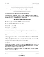
LMV52 Software Update: Version 0450 to 0480 (continued)
8. A parasitic effect in the QRI2 flame scanner during the reset phase leads to a short signal
pulse. Thus, flame evaluation during the reset is now delayed so the signal is ignored.
LMV52 Software Update: Version 0480 to 0510
The following updates were made with LMV52 software version 0510:
1. A new option for flame supervision via an external, safety-related flame safeguard.
2. Continuous pilot is available for fuel trains using a pilot. If activated, the pilot valve remains
open through phase 62.
3. A new calculation process is available for O
2
pre-control. The
Type ofAirChange
parameter
was enhanced to include the “
LambdaFact1”
setting option.
4. When setting the O
2
setpoint curve, the minimum intervals accepted by the LMV52 have
been reduced as follows:
•
Interval between O
2
ratio control curve and O
2
setpoint curve: from 1% to 0.1%
•
Interval between O
2
setpoint curve and O
2
alarm curve: from 0.5% to 0.1%
5. In O
2
operating mode “
conAutoDeac
”,
when the O
2
falls below the O
2
alarm value, the LMV5
initially operates along the ratio control curves. O
2
trim control is only deactivated
automatically once the
NumMinUntilDeact
repetition counter has elapsed
.
The minimum O
2
alarm remains active even once O
2
trim control has been deactivated.
6. Omission of the waiting time following interruptions to the power supply if the QGO20 cell
temperature is greater than 1274 °F [690 °C] on startup.
7. O
2
trim control behavior can be altered using the
O2TrimBehavior
parameter.
8. Limitations of the O
2
controller manipulated variable are now available via new parameters
O2MinManVariable
and
O2MaxManVariable
.
9. Activation / deactivation of O
2
trim control via an external contact can be configured at input
X5-03.3 using parameter
Config X5-03
.
10. The status of the O
2
controller can be displayed via data point
State O2 Ctrl
.
11. The O
2
maximum value alarm has been revised. It can now be the O
2
ratio control curve or
a set value. This is programmed via parameters
Type O2 MaxValue
and
O2 MaxValue
.
12. A new service timer for the O
2
sensor is now available. This can be adjusted via parameter
O2SensServTim
and reset via parameter
O2SensServTimRes
.
13. In order to calculate the combustion efficiency, the supply air temperature sensor can now
be connected to input X60 as well as to input X87 on the PLL52 which was already available.
HOME
Содержание LMV 5 Series
Страница 2: ...Intentionally Left Blank ...
Страница 25: ...LMV Series Technical Instructions Document No LV5 1000 SCC Inc Page 21 Section 1 Intentionally Left Blank HOME ...
Страница 27: ...LMV Series Technical Instructions Document No LV5 1000 SCC Inc Page 23 Section 1 Intentionally Left Blank HOME ...
Страница 41: ...LMV Series Technical Instructions Document No LV5 1000 SCC Inc Page 7 Section 2 HOME ...
Страница 42: ...Technical Instructions LMV Series Document No LV5 1000 Section 2 Page 8 SCC Inc HOME ...
Страница 43: ...LMV Series Technical Instructions Document No LV5 1000 SCC Inc Page 9 Section 2 HOME ...
Страница 44: ...Technical Instructions LMV Series Document No LV5 1000 Section 2 Page 10 SCC Inc HOME ...
Страница 45: ...LMV Series Technical Instructions Document No LV5 1000 SCC Inc Page 11 Section 2 HOME ...
Страница 46: ...Technical Instructions LMV Series Document No LV5 1000 Section 2 Page 12 SCC Inc HOME ...
Страница 47: ...LMV Series Technical Instructions Document No LV5 1000 SCC Inc Page 13 Section 2 HOME ...
Страница 48: ...Technical Instructions LMV Series Document No LV5 1000 Section 2 Page 14 SCC Inc HOME ...
Страница 49: ...LMV Series Technical Instructions Document No LV5 1000 SCC Inc Page 15 Section 2 HOME ...
Страница 50: ...Technical Instructions LMV Series Document No LV5 1000 Section 2 Page 16 SCC Inc HOME ...
Страница 51: ...LMV Series Technical Instructions Document No LV5 1000 SCC Inc Page 17 Section 2 HOME ...
Страница 52: ...Technical Instructions LMV Series Document No LV5 1000 Section 2 Page 18 SCC Inc HOME ...
Страница 53: ...LMV Series Technical Instructions Document No LV5 1000 SCC Inc Page 19 Section 2 HOME ...
Страница 54: ...Technical Instructions LMV Series Document No LV5 1000 Section 2 Page 20 SCC Inc HOME ...
Страница 55: ...LMV Series Technical Instructions Document No LV5 1000 SCC Inc Page 21 Section 2 HOME ...
Страница 56: ...Technical Instructions LMV Series Document No LV5 1000 Section 2 Page 22 SCC Inc Intentionally Left Blank HOME ...
Страница 116: ...Technical Instructions LMV Series Document No LV5 1000 Section 3 Page 58 SCC Inc Intentionally Left Blank HOME ...
Страница 150: ...Technical Instructions LMV Series Document No LV5 1000 Section 4 Page 32 SCC Inc Intentionally Left Blank HOME ...
Страница 170: ...Technical Instructions LMV Series Document No LV5 1000 Section 5 Page 18 SCC Inc Intentionally Left Blank HOME ...
Страница 290: ...Technical Instructions LMV Series Document No LV5 1000 Section 8 Page 20 SCC Inc Intentionally Left Blank HOME ...
Страница 306: ...Technical Instructions LMV Series Document No LV5 1000 Section 9 Page 14 SCC Inc Intentionally Left Blank HOME ...
Страница 373: ...Intentionally Left Blank ...