


LMV
Series
Technical
Instructions
Document
No.
LV5
‐
1000
SCC
Inc.
Page
29
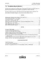
Section
6
Considerations
when
Using
O
2
Trim
with
FGR
Some
burners
use
a
high
percentage
of
FGR
(FGR
flow
compared
to
air
flow)
to
lower
NOx
emissions.
Since
flue
gases
change
in
%O
2
and
are
being
drawn
back
into
the
blower
in
significant
quantities,
these
types
of
burners
are
inherently
more
difficult
to
trim
the
%O
2
in
the
stack.
The
reason
behind
this
increased
difficulty
is
the
oxygen
content
of
the
air
/
FGR
mixture
is
dependent
on
the
%O
2
in
the
stack,
which
adds
another
dynamic
variable
into
the
system.
On
a
burner
without
FGR,
the
oxygen
content
of
the
air
at
the
blower
intake
is
always
a
constant
20.9%
O
2
.
Naturally,
a
larger
percentage
of
FGR
(20%)
has
the
potential
to
vary
the
oxygen
content
of
the
air
/
FGR
mixture
at
the
blower
intake
more
than
a
small
percentage
of
FGR
(5%)
would.
Moreover,
a
large
percentage
of
FGR
can
change
the
oxygen
content
of
the
air
/
FGR
mixture
at
the
blower
intake
in
a
way
that
can
set
up
a
"cycle
of
intensification".
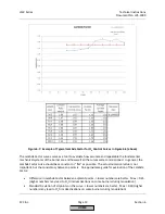
An
example
of
this
cycle
is
below:
1.
The
%O
2
in
the
stack
increases
for
some
reason.
2.
The
%O
2
in
the
FGR
also
increases.
3.
The
oxygen
content
of
the
air
/
FGR
mixture
at
the
blower
intake
increases,
which
increases
the
%O
2
in
the
stack
even
more.
Naturally,
the
example
above
would
also
hold
if
the
%O
2
in
the
stack
decreased,
except
the
cycle
of
intensification
would
serve
to
push
the
burner
rich
instead
of
lean.
In
addition
to
the
cycle
of
intensification
that
is
inherent
to
many
FGR
burners,
the
mechanical
design
of
the
burner
/
boiler
influences
the
repeatability
of
the
FGR
flow.
The
repeatability
of
the
FGR
flow
has
a
large
influence
on
how
well
the
O
2
trim
system
can
work.
Obviously,
non
‐
repeatability
in
the
FGR
flow
will
cause
non
‐
repeatability
in
the
%O
2
read
in
the
stack
and
therefore
the
operation
of
the
O
2
trim.
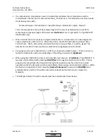
Two
different
methods
of
inducing
FGR
into
a
burner
are
illustrated
and
explained
below,
and
their
behaviors
from
an
FGR
flow
repeatability
standpoint
are
discussed.
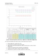
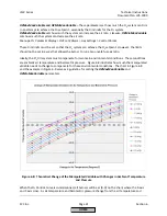
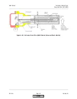
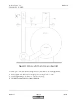
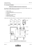
Method
shown
in
Figure
6
‐
12:
Pressure
P1
relative
to
pressure
P2
(differential
pressure
across
the
FGR
damper)
changes
drastically
with
firing
rate.
Very
little
differential
pressure
will
be
generated
across
the
FGR
damper
at
low
fire,
requiring
the
FGR
damper
to
be
mostly
open
to
achieve
even
minimal
FGR
flow
at
low
fire.
As
firing
rate
increases,
P1
will
decrease
and
P2
will
increase,
yielding
much
more
differential
pressure
across
the
FGR
damper.
As
a
result,
the
FGR
damper
will
need
to
be
ramped
closed
as
the
burner
is
ramped
up
to
high
fire.
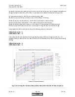
Due
to
the
much
higher
differential
pressure
at
high
fire
the
FGR
damper
might
be
oversized
for
effective
control
at
high
fire.
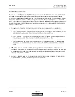
Other
points
to
consider:
1.
If
using
O
2
trim,
trimming
with
the
air
actuator
(set
to
"air
influenced")
closed
should
serve
to
decrease
P1
and
decrease
the
FGR
flow
slightly
(depending
on
the
position
of
the
stack
damper).
2.
At
low
fire
when
the
FGR
valve
is
mostly
open,
even
small
changes
in
the
differential
pressure
across
the
FGR
damper
will
cause
large
changes
in
FGR
flow.
HOME
Содержание LMV 5 Series
Страница 2: ...Intentionally Left Blank ...
Страница 25: ...LMV Series Technical Instructions Document No LV5 1000 SCC Inc Page 21 Section 1 Intentionally Left Blank HOME ...
Страница 27: ...LMV Series Technical Instructions Document No LV5 1000 SCC Inc Page 23 Section 1 Intentionally Left Blank HOME ...
Страница 41: ...LMV Series Technical Instructions Document No LV5 1000 SCC Inc Page 7 Section 2 HOME ...
Страница 42: ...Technical Instructions LMV Series Document No LV5 1000 Section 2 Page 8 SCC Inc HOME ...
Страница 43: ...LMV Series Technical Instructions Document No LV5 1000 SCC Inc Page 9 Section 2 HOME ...
Страница 44: ...Technical Instructions LMV Series Document No LV5 1000 Section 2 Page 10 SCC Inc HOME ...
Страница 45: ...LMV Series Technical Instructions Document No LV5 1000 SCC Inc Page 11 Section 2 HOME ...
Страница 46: ...Technical Instructions LMV Series Document No LV5 1000 Section 2 Page 12 SCC Inc HOME ...
Страница 47: ...LMV Series Technical Instructions Document No LV5 1000 SCC Inc Page 13 Section 2 HOME ...
Страница 48: ...Technical Instructions LMV Series Document No LV5 1000 Section 2 Page 14 SCC Inc HOME ...
Страница 49: ...LMV Series Technical Instructions Document No LV5 1000 SCC Inc Page 15 Section 2 HOME ...
Страница 50: ...Technical Instructions LMV Series Document No LV5 1000 Section 2 Page 16 SCC Inc HOME ...
Страница 51: ...LMV Series Technical Instructions Document No LV5 1000 SCC Inc Page 17 Section 2 HOME ...
Страница 52: ...Technical Instructions LMV Series Document No LV5 1000 Section 2 Page 18 SCC Inc HOME ...
Страница 53: ...LMV Series Technical Instructions Document No LV5 1000 SCC Inc Page 19 Section 2 HOME ...
Страница 54: ...Technical Instructions LMV Series Document No LV5 1000 Section 2 Page 20 SCC Inc HOME ...
Страница 55: ...LMV Series Technical Instructions Document No LV5 1000 SCC Inc Page 21 Section 2 HOME ...
Страница 56: ...Technical Instructions LMV Series Document No LV5 1000 Section 2 Page 22 SCC Inc Intentionally Left Blank HOME ...
Страница 116: ...Technical Instructions LMV Series Document No LV5 1000 Section 3 Page 58 SCC Inc Intentionally Left Blank HOME ...
Страница 150: ...Technical Instructions LMV Series Document No LV5 1000 Section 4 Page 32 SCC Inc Intentionally Left Blank HOME ...
Страница 170: ...Technical Instructions LMV Series Document No LV5 1000 Section 5 Page 18 SCC Inc Intentionally Left Blank HOME ...
Страница 290: ...Technical Instructions LMV Series Document No LV5 1000 Section 8 Page 20 SCC Inc Intentionally Left Blank HOME ...
Страница 306: ...Technical Instructions LMV Series Document No LV5 1000 Section 9 Page 14 SCC Inc Intentionally Left Blank HOME ...
Страница 373: ...Intentionally Left Blank ...