

Technical
Instructions
LMV
Series
Document
No.
LV5
‐
1000
Section
6
Page
20
SCC
Inc.
Post
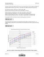
Commissioning
Tuning
After
the
O
2
curves
have
been
set
up
according
to
the
procedures
above,
some
additional
burner
/
boiler
specific
tuning
may
be
necessary
to
keep
the
O
2
trim
operating
properly.
When
and
how
to
use
these
tuning
parameters
is
discussed
below.
LoadCtrlSuspend
‐
This
sets
the
load
change
that
is
necessary
to
make
the
O
2
trim
transition
from
active
O
2
trim
to
pre
‐
control.
Many
factors
influence
the
setting
of
this
parameter.
Menu
path:
Params
&
Display
>
O2Contr/Alarm
>
Gas
Settings
>
Control
Param
Higher
settings
(more
active
trim,
less
pre
‐
control)
can
help
the
O
2
trim
stay
close
to
setpoint
in
the
following
situations:
1.
The
O
2
Control
Curve
is
relatively
flat
from
low
fire
to
high
fire
(varies
less
than
0.5%
O
2
)
2.
The
modulation
ramp
time
is
slow
(
OperatRampMod
is
set
to
60
seconds
or
more)
3.
The
delay
time
(Tau
time)
of
the
boiler
is
relatively
fast
(
Tau
Low
‐
Fire
is
set
to
7
seconds
or
less)
Lower
settings
(less
active
trim,
more
pre
‐
control)
can
help
the
O
2
trim
stay
close
to
setpoint
in
the
following
situations:
1.
The
O
2
Control
Curve
slopes
from
low
fire
to
high
fire
(varies
more
than
0.5%
O
2
)
2.
The
modulation
ramp
time
is
fast
(
OperatRampMod
is
set
to
30
seconds)
3.
The
delay
time
(Tau
time)
of
the
boiler
is
slow
(
Tau
Low
‐
Fire
is
set
for
more
than
7
seconds)
O2TrimBehavior
‐
If
parameter
Startmode
is
set
to
“standard”,
this
setting
controls
how
the
O
2
trim
responds
if
the
measured
O
2
value
starts
to
move
away
from
the
O
2
setpoint
significantly.
Menu
path:
Params
&
Display
>
O2Contr/Alarm
>
Gas
Settings
>
Control
Param
1.
A
setting
of
“ForcedAirAdd”
will
help
if
deactivations
are
due
to
the
rich
limit
(O
2
alarm)
since
air
will
be
added
more
aggressively.
2.
A
setting
of
“ForcedAirRed”
will
help
if
deactivations
are
due
to
the
lean
limit
(
O2
MaxValue
)
since
air
will
be
subtracted
more
aggressively.
3.
A
setting
of
“symmetric”
is
used
when
the
rich
limit
(O
2
alarm)
and
the
lean
limit
(
O2
MaxValue
)
are
relatively
close
together,
and
an
aggressive
correction
in
one
direction
might
cause
a
deactivation
due
to
the
other
limit.
NOTE:
On
an
LMV52.440
with
the
StartMode
set
to
something
other
than
“standard”,
the
setting
of
O2TrimBehavior
has
no
effect.
O2ModOffset
‐
During
a
load
change
when
the
pre
‐
control
becomes
active
(see
LoadCtrlSuspend
),
this
will
temporarily
add
more
air
beyond
what
is
prescribed
by
the
Lambda
Factor.
Increasing
this
setting
can
help
with
rich
limit
(O
2
alarm)
deactivations
during
modulation,
but
this
parameter
should
not
be
used
as
a
substitute
for
proper
O
2
trim
commissioning
procedures.
Menu
path:
Params
&
Display
>
O2Contr/Alarm
>
Gas
Settings
>
Control
Param
HOME
Содержание LMV 5 Series
Страница 2: ...Intentionally Left Blank ...
Страница 25: ...LMV Series Technical Instructions Document No LV5 1000 SCC Inc Page 21 Section 1 Intentionally Left Blank HOME ...
Страница 27: ...LMV Series Technical Instructions Document No LV5 1000 SCC Inc Page 23 Section 1 Intentionally Left Blank HOME ...
Страница 41: ...LMV Series Technical Instructions Document No LV5 1000 SCC Inc Page 7 Section 2 HOME ...
Страница 42: ...Technical Instructions LMV Series Document No LV5 1000 Section 2 Page 8 SCC Inc HOME ...
Страница 43: ...LMV Series Technical Instructions Document No LV5 1000 SCC Inc Page 9 Section 2 HOME ...
Страница 44: ...Technical Instructions LMV Series Document No LV5 1000 Section 2 Page 10 SCC Inc HOME ...
Страница 45: ...LMV Series Technical Instructions Document No LV5 1000 SCC Inc Page 11 Section 2 HOME ...
Страница 46: ...Technical Instructions LMV Series Document No LV5 1000 Section 2 Page 12 SCC Inc HOME ...
Страница 47: ...LMV Series Technical Instructions Document No LV5 1000 SCC Inc Page 13 Section 2 HOME ...
Страница 48: ...Technical Instructions LMV Series Document No LV5 1000 Section 2 Page 14 SCC Inc HOME ...
Страница 49: ...LMV Series Technical Instructions Document No LV5 1000 SCC Inc Page 15 Section 2 HOME ...
Страница 50: ...Technical Instructions LMV Series Document No LV5 1000 Section 2 Page 16 SCC Inc HOME ...
Страница 51: ...LMV Series Technical Instructions Document No LV5 1000 SCC Inc Page 17 Section 2 HOME ...
Страница 52: ...Technical Instructions LMV Series Document No LV5 1000 Section 2 Page 18 SCC Inc HOME ...
Страница 53: ...LMV Series Technical Instructions Document No LV5 1000 SCC Inc Page 19 Section 2 HOME ...
Страница 54: ...Technical Instructions LMV Series Document No LV5 1000 Section 2 Page 20 SCC Inc HOME ...
Страница 55: ...LMV Series Technical Instructions Document No LV5 1000 SCC Inc Page 21 Section 2 HOME ...
Страница 56: ...Technical Instructions LMV Series Document No LV5 1000 Section 2 Page 22 SCC Inc Intentionally Left Blank HOME ...
Страница 116: ...Technical Instructions LMV Series Document No LV5 1000 Section 3 Page 58 SCC Inc Intentionally Left Blank HOME ...
Страница 150: ...Technical Instructions LMV Series Document No LV5 1000 Section 4 Page 32 SCC Inc Intentionally Left Blank HOME ...
Страница 170: ...Technical Instructions LMV Series Document No LV5 1000 Section 5 Page 18 SCC Inc Intentionally Left Blank HOME ...
Страница 290: ...Technical Instructions LMV Series Document No LV5 1000 Section 8 Page 20 SCC Inc Intentionally Left Blank HOME ...
Страница 306: ...Technical Instructions LMV Series Document No LV5 1000 Section 9 Page 14 SCC Inc Intentionally Left Blank HOME ...
Страница 373: ...Intentionally Left Blank ...