

Technical
Instructions
LMV
Series
Document
No.
LV5
‐
1000
Section
6
Page
4
SCC
Inc.
For
many
nozzle
mixing
burners
(traditional
boiler
burners),
the
O
2
setpoint
will
be
a
higher
value
at
low
fire
and
a
lower
value
at
high
fire.
This
is
true
since
most
nozzle
mixing
burners
need
more
excess
air
(higher
O
2
)
at
low
fire
to
achieve
complete
combustion.
For
this
type
of
burner
an
O
2
setpoint
of
5%
O
2
(wet)
at
low
fire
and
an
O
2
setpoint
of
2%
O
2
(wet)
at
high
fire
is
not
uncommon.
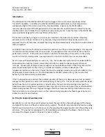
Pre
‐
control
As
mentioned
above,
all
O
2
trim
systems
with
an
O
2
sensor
in
the
boiler's
exhaust
must
use
"old"
O
2
readings
due
to
physical
realities
of
the
boiler.
This
fact,
combined
with
an
O
2
setpoint
that
typically
varies
from
low
fire
to
high
fire
means
that
the
O
2
trim
system
cannot
actively
trim
when
the
burner
makes
a
large
change
in
firing
rate.
This
begs
the
question
of
what
happens
to
the
O
2
trim
when
the
burner
transitions
from
20%
firing
rate
to,
say,
80%
firing
rate.
The
answer
is
the
O
2
trim
changes
modes
from
active
trim
to
what
is
referred
to
as
"pre
‐
control".
Pre
‐
control
is
possible
because
the
LMV52
learns
the
characteristic
of
the
burner
at
each
point
on
the
curve
during
the
O
2
trim
commissioning.
The
specific
characteristic
that
the
LMV52
learns
is
how
much
of
a
change
in
airflow
(air
rate)
is
necessary
to
achieve
a
certain
change
in
the
%O
2
.
This
specific
characteristic
is
known
as
the
Lambda
Factor,
and
is
essentially
the
burner's
signature
from
an
O
2
trim
standpoint.
Just
like
the
delay
time
(Tau
time)
that
was
mentioned
earlier,
it
is
necessary
for
the
fuel
flow
to
match
the
load
number
so
that
the
Lambda
Factor
is
correct
and
accurate
for
each
point.
Pre
‐
control
uses
the
Lambda
Factor
so
that
the
burner
can
be
modulated
while
keeping
the
%O
2
close
to
the
O
2
setpoint,
even
though
the
setpoint
changes
with
the
firing
rate
and
the
O
2
trim
is
using
"old"
O
2
readings.
Once
the
burner
stops
modulating
or
only
modulates
a
small
amount
(+/
‐
5%),
the
O
2
trim
will
change
modes
back
to
"active"
and
perform
active
O
2
trim
once
again.
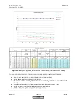
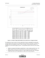
A
properly
commissioned
O
2
trim
system
will
typically
maintain
the
%O
2
setpoint
with
a
deviation
of
+/
‐
0.1%
O
2
when
the
burner
is
not
modulating
a
significant
amount
(+/
‐
5%
load
change).
With
this
small
load
change,
the
O
2
trim
will
stay
in
the
"active"
mode.
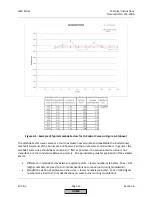
When
significant
modulation
is
encountered
(+/
‐
15%
load
change),
the
pre
‐
control
will
engage
and
the
deviation
from
setpoint
will
increase.
Deviations
of
+/
‐
0.3%
or
less
are
typical
during
modulation
when
the
pre
‐
control
is
engaged.
O
2
Trim
Terminology
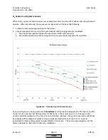
1.
%O
2
Wet
–
In
‐
situ
O
2
sensors,
like
the
QGO20
sensor
that
is
used
with
the
LMV52,
read
the
%O
2
on
a
wet
basis.
This
is
in
contrast
to
the
vast
majority
of
portable
combustion
analyzers
that
read
%O
2
on
a
dry
basis.
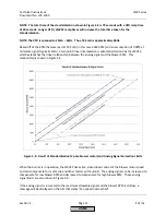
%O
2
wet
should
always
be
a
lower
value
than
%O
2
dry.
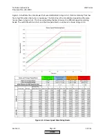
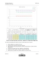
Figure
6
‐
11
(located
later
in
this
section)
gives
the
approximate
relationship
between
%O
2
wet
and
%O
2
dry.
2.
Tau
Time
‐
This
is
the
delay
time
between
when
an
adjustment
is
made
at
the
burner
(moving
the
air
damper,
etc.)
and
when
that
adjustment
is
read
at
the
O
2
sensor.
For
a
given
burner
/
boiler,
this
time
will
be
shorter
at
high
fire
and
longer
at
low
fire.
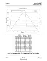
3.
O
2
Ratio
Control
‐
This
is
the
measured
%O
2
wet
when
the
actuators
/
VSD
are
on
the
Fuel
‐
Air
Ratio
Control
Curve
and
are
not
being
trimmed.
This
is
recorded
for
each
point
on
the
curve
except
Point
1.
This
is
also
commonly
referred
to
as
the
“lean
curve”.
HOME
Содержание LMV 5 Series
Страница 2: ...Intentionally Left Blank ...
Страница 25: ...LMV Series Technical Instructions Document No LV5 1000 SCC Inc Page 21 Section 1 Intentionally Left Blank HOME ...
Страница 27: ...LMV Series Technical Instructions Document No LV5 1000 SCC Inc Page 23 Section 1 Intentionally Left Blank HOME ...
Страница 41: ...LMV Series Technical Instructions Document No LV5 1000 SCC Inc Page 7 Section 2 HOME ...
Страница 42: ...Technical Instructions LMV Series Document No LV5 1000 Section 2 Page 8 SCC Inc HOME ...
Страница 43: ...LMV Series Technical Instructions Document No LV5 1000 SCC Inc Page 9 Section 2 HOME ...
Страница 44: ...Technical Instructions LMV Series Document No LV5 1000 Section 2 Page 10 SCC Inc HOME ...
Страница 45: ...LMV Series Technical Instructions Document No LV5 1000 SCC Inc Page 11 Section 2 HOME ...
Страница 46: ...Technical Instructions LMV Series Document No LV5 1000 Section 2 Page 12 SCC Inc HOME ...
Страница 47: ...LMV Series Technical Instructions Document No LV5 1000 SCC Inc Page 13 Section 2 HOME ...
Страница 48: ...Technical Instructions LMV Series Document No LV5 1000 Section 2 Page 14 SCC Inc HOME ...
Страница 49: ...LMV Series Technical Instructions Document No LV5 1000 SCC Inc Page 15 Section 2 HOME ...
Страница 50: ...Technical Instructions LMV Series Document No LV5 1000 Section 2 Page 16 SCC Inc HOME ...
Страница 51: ...LMV Series Technical Instructions Document No LV5 1000 SCC Inc Page 17 Section 2 HOME ...
Страница 52: ...Technical Instructions LMV Series Document No LV5 1000 Section 2 Page 18 SCC Inc HOME ...
Страница 53: ...LMV Series Technical Instructions Document No LV5 1000 SCC Inc Page 19 Section 2 HOME ...
Страница 54: ...Technical Instructions LMV Series Document No LV5 1000 Section 2 Page 20 SCC Inc HOME ...
Страница 55: ...LMV Series Technical Instructions Document No LV5 1000 SCC Inc Page 21 Section 2 HOME ...
Страница 56: ...Technical Instructions LMV Series Document No LV5 1000 Section 2 Page 22 SCC Inc Intentionally Left Blank HOME ...
Страница 116: ...Technical Instructions LMV Series Document No LV5 1000 Section 3 Page 58 SCC Inc Intentionally Left Blank HOME ...
Страница 150: ...Technical Instructions LMV Series Document No LV5 1000 Section 4 Page 32 SCC Inc Intentionally Left Blank HOME ...
Страница 170: ...Technical Instructions LMV Series Document No LV5 1000 Section 5 Page 18 SCC Inc Intentionally Left Blank HOME ...
Страница 290: ...Technical Instructions LMV Series Document No LV5 1000 Section 8 Page 20 SCC Inc Intentionally Left Blank HOME ...
Страница 306: ...Technical Instructions LMV Series Document No LV5 1000 Section 9 Page 14 SCC Inc Intentionally Left Blank HOME ...
Страница 373: ...Intentionally Left Blank ...