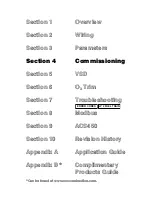
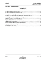

Technical
Instructions
LMV
Series
Document
No.
LV5
‐
1000
Section
4
Page
14
SCC
Inc.
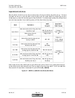
13.
At
this
point,
all
other
LMV5
parameters
under
the
“BurnerControl”
and
“RatioControl”
headings
should
be
reviewed
and
set
accordingly
for
the
individual
burner
requirements.
Params
&
Display
>
BurnerControl
Params
&
Display
>
RatioControl
Section
3
of
this
literature
explains
every
parameter
in
detail,
and
the
most
commonly
used
parameters
are
shaded
for
easy
reference.
14.
If
the
burner
has
a
Variable
Speed
Drive
(VSD)
on
the
blower,
it
must
be
standardized.
In
most
cases,
the
VSD
is
a
Variable
Frequency
Drive
(VFD).
See
Section
5
in
this
literature
if
the
VFD
parameters
are
not
already
set,
and
for
a
more
detailed
standardization
procedure.
If
the
VFD
parameters
are
set,
standardize
the
VFD
using
the
following
menu
path:
Params
&
Display
>
VSD
Module
>
Configuration
>
Speed
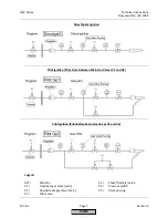
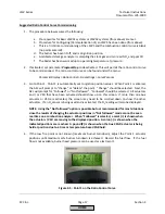
Once
Standardization
is
set
to
“activated”,
the
air
damper
should
open
to
its
pre
‐
purge
position,
and
the
blower
should
ramp
up,
pause,
and
then
ramp
back
down.
If
this
does
not
occur,
make
sure
that
the
VSD
is
set
to
“air
influenced”
and
the
safety
loop
is
closed.
Transferring
Parameter
Sets
Using
the
AZL
Display
This
procedure
will
detail
how
to
transfer
a
parameter
set
from
one
burner
to
another
burner.
In
this
example,
the
parameter
set
will
originate
from
Burner
#1
(B1)
and
will
be
copied
to
Burner
#2
(B2).
Naturally,
using
a
similar
procedure,
the
parameter
set
from
Burner
#1
can
be
copied
to
Burners
#3,
#4,
#5,
etc.
The
ACS450
PC
software
can
also
be
used
for
this
purpose
(see
Section
9).
Note:
Passwords
are
transferred
with
the
parameter
sets.
Manual
operation
settings
are
not
transferred
with
parameter
sets.
1.
Obtain
the
OEM
or
service
level
passwords
for
B1
and
B2.
2.
On
B1,
upload
all
of
the
current
parameters
from
the
LMV5
to
the
AZL
flash
memory
using
the
following
menu
path:
Updating
>
ParamBackup
>
LMV5x
‐
>
AZL
The
OEM
or
service
level
password
for
B1
will
be
necessary
to
access
this.
This
will
upload
all
of
the
current
LMV5
parameters
to
the
AZL
flash
memory.
This
process
is
complete
when
the
AZL
states
"Parameters
have
been
stored".
If
the
LMV5
on
B2
is
known
to
have
a
blank
burner
ID,
then
power
off
B1
LMV5,
remove
the
AZL,
and
skip
to
step
5.
Otherwise,
go
to
the
next
step.
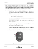
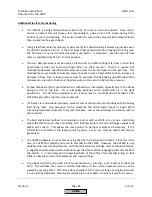
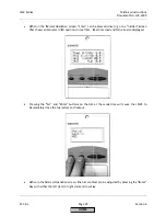
3.
Write
down
B1
burner
ID.
This
can
be
found
at
the
following
menu
path:
Operation
>
Burner
ID
After
this
step,
B1
LMV5
can
be
powered
off.
After
B1
is
powered
off,
remove
the
AZL.
HOME
Содержание LMV 5 Series
Страница 2: ...Intentionally Left Blank ...
Страница 25: ...LMV Series Technical Instructions Document No LV5 1000 SCC Inc Page 21 Section 1 Intentionally Left Blank HOME ...
Страница 27: ...LMV Series Technical Instructions Document No LV5 1000 SCC Inc Page 23 Section 1 Intentionally Left Blank HOME ...
Страница 41: ...LMV Series Technical Instructions Document No LV5 1000 SCC Inc Page 7 Section 2 HOME ...
Страница 42: ...Technical Instructions LMV Series Document No LV5 1000 Section 2 Page 8 SCC Inc HOME ...
Страница 43: ...LMV Series Technical Instructions Document No LV5 1000 SCC Inc Page 9 Section 2 HOME ...
Страница 44: ...Technical Instructions LMV Series Document No LV5 1000 Section 2 Page 10 SCC Inc HOME ...
Страница 45: ...LMV Series Technical Instructions Document No LV5 1000 SCC Inc Page 11 Section 2 HOME ...
Страница 46: ...Technical Instructions LMV Series Document No LV5 1000 Section 2 Page 12 SCC Inc HOME ...
Страница 47: ...LMV Series Technical Instructions Document No LV5 1000 SCC Inc Page 13 Section 2 HOME ...
Страница 48: ...Technical Instructions LMV Series Document No LV5 1000 Section 2 Page 14 SCC Inc HOME ...
Страница 49: ...LMV Series Technical Instructions Document No LV5 1000 SCC Inc Page 15 Section 2 HOME ...
Страница 50: ...Technical Instructions LMV Series Document No LV5 1000 Section 2 Page 16 SCC Inc HOME ...
Страница 51: ...LMV Series Technical Instructions Document No LV5 1000 SCC Inc Page 17 Section 2 HOME ...
Страница 52: ...Technical Instructions LMV Series Document No LV5 1000 Section 2 Page 18 SCC Inc HOME ...
Страница 53: ...LMV Series Technical Instructions Document No LV5 1000 SCC Inc Page 19 Section 2 HOME ...
Страница 54: ...Technical Instructions LMV Series Document No LV5 1000 Section 2 Page 20 SCC Inc HOME ...
Страница 55: ...LMV Series Technical Instructions Document No LV5 1000 SCC Inc Page 21 Section 2 HOME ...
Страница 56: ...Technical Instructions LMV Series Document No LV5 1000 Section 2 Page 22 SCC Inc Intentionally Left Blank HOME ...
Страница 116: ...Technical Instructions LMV Series Document No LV5 1000 Section 3 Page 58 SCC Inc Intentionally Left Blank HOME ...
Страница 150: ...Technical Instructions LMV Series Document No LV5 1000 Section 4 Page 32 SCC Inc Intentionally Left Blank HOME ...
Страница 170: ...Technical Instructions LMV Series Document No LV5 1000 Section 5 Page 18 SCC Inc Intentionally Left Blank HOME ...
Страница 290: ...Technical Instructions LMV Series Document No LV5 1000 Section 8 Page 20 SCC Inc Intentionally Left Blank HOME ...
Страница 306: ...Technical Instructions LMV Series Document No LV5 1000 Section 9 Page 14 SCC Inc Intentionally Left Blank HOME ...
Страница 373: ...Intentionally Left Blank ...