Commissioning
6.3 RUN mode
HydroRanger 200 HMI
54
Operating Instructions, 06/2018, A5E36281317-AC
6.3.3
Auxiliary reading
Measurement View 2 displays an Auxiliary Reading area in addition to the Primary Reading.
The Auxiliary Reading can display additional information that you choose.
Setting a specific Auxiliary Reading
To set the value initially displayed in the Auxiliary Reading, use Default auxiliary reading
(2.12.7.) (Page 239).
The Auxiliary Reading value that you choose is automatically synchronized with the Primary
Reading value as the display scrolls through the Level Points. For example, if the Primary
Reading is Level and you have chosen Volume for the Auxiliary Reading, the device will
always show Level (in the Primary) and Volume (in the Auxiliary) for the same Level Point.
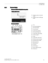
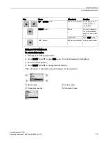
The Level Point is shown in Measurement Mode Display as caption number 6 on the local
display diagram (Page 51).
Temporarily overriding the Auxiliary Reading
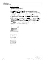
You can temporarily override the value displayed in the Auxiliary Reading by pressing the
arrow in RUN mode. This allows you to see values in the Auxiliary Reading area that are not
associated with a particular Level Point.
For example, you may have configured the Primary Reading to display Flow, and the
Auxiliary Reading to display Head. If you want to see what the milliamp outputs are, you can
press the arrow. This first press of arrow will temporarily replace the Auxiliary Reading
with milliamp output #1. Press the arrow again to display milliamp output #2, and press it
a third time to see the milliamp input.
The device will continue to display your selected temporary value until the next power cycle.
After a power cycle, the device will show the default auxiliary reading [see Default auxiliary
reading (2.12.7.) (Page 239) ] when you display Measurement View 2.
6.3.4
Multiple readings
During differential or average operation [Sensor Mode (2.3.1.) (Page 163) = Dual-Point
Difference/Dual-Point Average (Page 163) ], Measurement Views 1 and 2 scrolls
sequentially through Point Numbers 1, 2, and 3. Point 3 is the difference between (or
average of) Points 1 and 2.
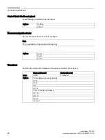
Changing number scrolling speed
Parameter
Value
Description
(Page 239)
5
Hold each value for 5 seconds
Содержание HydroRanger 200 HMI
Страница 2: ......
Страница 20: ...Introduction 1 5 Notes on warranty HydroRanger 200 HMI 18 Operating Instructions 06 2018 A5E36281317 AC ...
Страница 24: ...Safety notes HydroRanger 200 HMI 22 Operating Instructions 06 2018 A5E36281317 AC ...
Страница 28: ...Description 3 5 Modbus communication HydroRanger 200 HMI 26 Operating Instructions 06 2018 A5E36281317 AC ...
Страница 159: ...Parameter reference 8 2 Parameter indexing HydroRanger 200 HMI Operating Instructions 06 2018 A5E36281317 AC 157 ...
Страница 276: ...Parameter reference 8 10 Language 6 HydroRanger 200 HMI 274 Operating Instructions 06 2018 A5E36281317 AC ...
Страница 322: ...Pump control reference B 13 Other pump controls HydroRanger 200 HMI 320 Operating Instructions 06 2018 A5E36281317 AC ...
Страница 352: ...Communications C 41 Single parameter access SPA HydroRanger 200 HMI 350 Operating Instructions 06 2018 A5E36281317 AC ...
Страница 354: ...Updating software HydroRanger 200 HMI 352 Operating Instructions 06 2018 A5E36281317 AC ...
Страница 359: ...HydroRanger 200 HMI Operating Instructions 06 2018 A5E36281317 AC 357 Conduit entry for Class I Div 2 applications F ...
Страница 360: ...Conduit entry for Class I Div 2 applications HydroRanger 200 HMI 358 Operating Instructions 06 2018 A5E36281317 AC ...
Страница 361: ...Conduit entry for Class I Div 2 applications HydroRanger 200 HMI Operating Instructions 06 2018 A5E36281317 AC 359 ...
Страница 362: ......
Страница 372: ...Programming chart G 1 Programming chart HydroRanger 200 HMI 370 Operating Instructions 06 2018 A5E36281317 AC ...
Страница 390: ...LCD menu structure H 1 LCD Menu Structure HydroRanger 200 HMI 388 Operating Instructions 06 2018 A5E36281317 AC ...
Страница 403: ......


