background image

Parameter reference 


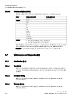
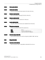
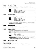
8.7 Maintenance and Diagnostics (3.) 


HydroRanger 200 HMI 

254


Operating Instructions, 06/2018, A5E36281317-AC 

8.7.2.2


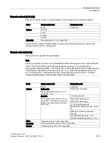
Echo profile (3.2.2.) 

Allows you to request the current echo profile either locally via the local push buttons, or 

remotely via SIMATIC PDM. 

To request a profile via the local push buttons: 
1.


In PROGRAM mode, navigate to MAIN MENU > DIAGNOSTICS > ECHO PROFILE 

2.


Press RIGHT arrow to request a profile. 


Note 
An Echo Profile (3.2.2.) cannot be requested when: 


Sensor Mode (2.1.3.) (Page 163) is out of service, or when 


Transducer (2.1.5.) (Page 164) is set to NO TRANSDUCER. 

 In either case, the local push button will not operate. 


For more detail, see Requesting an echo profile (Page 86). 
For more detail on how to request an echo profile, see Echo processing (Page 302). 

8.7.2.3


Master reset (3.2.3.) 

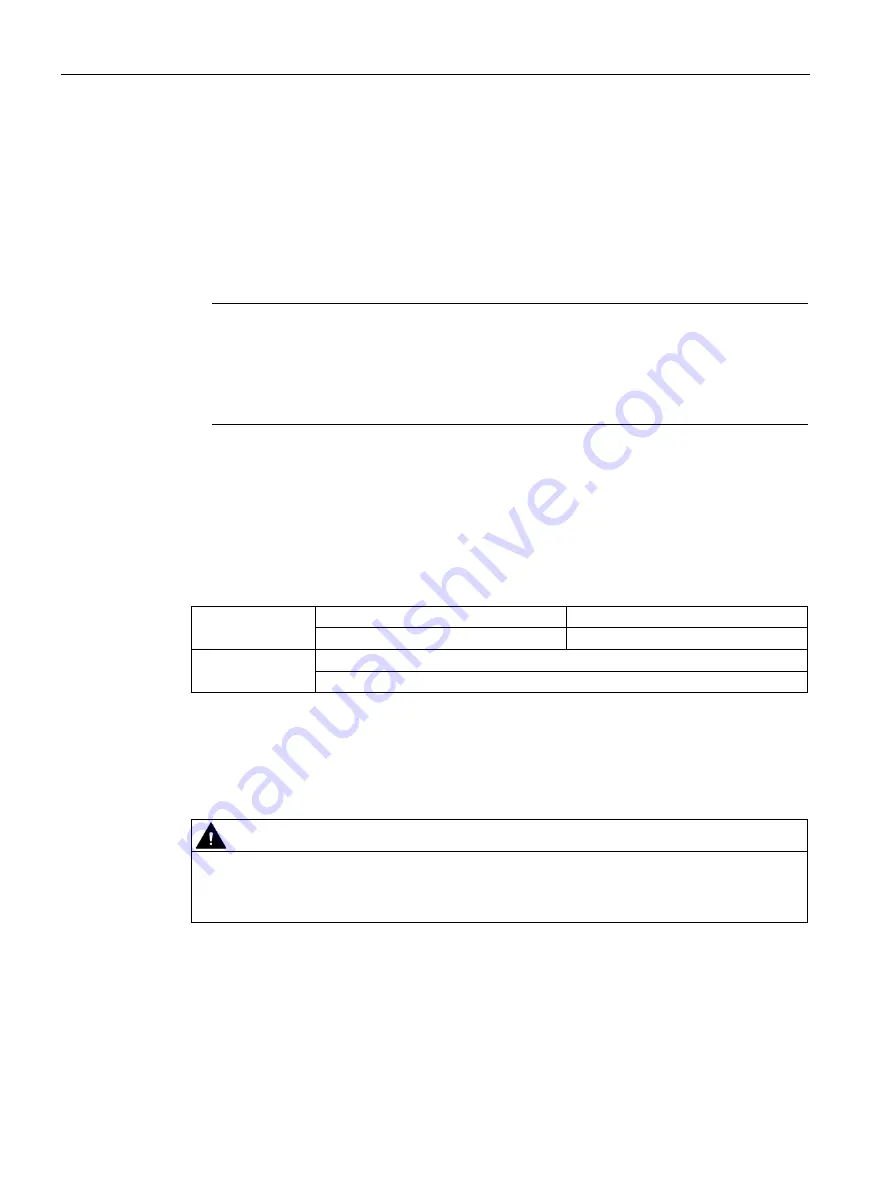
Resets all parameters to original values, with the exception of the AFES, TVT shaping, and 

all relative identification parameters (Tag, Description, etc.). 


Index 

Single-point model 

Dual-point model 

Global 

Transducer 

Global 

*Do nothing 
Factory defaults 

Use this feature prior to initial programming if arbitrary parameter values were used during a 

bench test, or after upgrading the software. Following a Master Reset, complete 

reprogramming is required. 
When the factory default option is selected, the display will pause while reset is processed. 

When the display returns to the Diagnostics menu, the Master Reset is complete. 


CAUTION 

Master Reset 
Be careful when using this feature. All data for all points will be reset. For convenience, be 

sure to record the values you want to re-enter. 


Содержание HydroRanger 200 HMI

Страница 1: ...Operating instructions HydroRanger 200 HMI Ultrasonic Controllers 06 2018 Edition SITRANS www siemens com processautomation ...

Страница 2: ......

Страница 3: ..._______ ___________________ ___________________ Ultrasonic controllers HydroRanger 200 HMI Operating Instructions 06 2018 A5E36281317 AC Introduction 1 Safety notes 2 Description 3 Installing mounting 4 Connecting 5 Commissioning 6 Operating 7 Parameter reference 8 Service and maintenance 9 Diagnosing and troubleshooting 10 Technical data 11 Technical reference A Pump control reference B Communica...

Страница 4: ...be operated only by personnel qualified for the specific task in accordance with the relevant documentation in particular its warning notices and safety instructions Qualified personnel are those who based on their training and experience are capable of identifying risks and avoiding potential hazards when working with these products systems Proper use of Siemens products Note the following WARNIN...

Страница 5: ...5 4 Installing mounting 27 4 1 Basic safety notes 27 4 2 Mounting Instructions 29 4 2 1 Mounting locations 29 4 2 2 Mounting on wall 29 4 2 3 Cable routed through a conduit 32 4 2 4 Cable exposed and entering through the cable glands 33 4 2 5 Panel mount 34 4 2 6 Cutout instructions 35 4 2 7 Panel mount dimensions 35 4 2 8 Mounting the enclosure 35 4 2 9 Wiring compartment 36 4 3 Wiring compartmen...

Страница 6: ...ode 55 6 4 1 Key functions in Measurement mode 55 6 4 2 Programming the device 55 6 4 3 Parameter menus 56 6 4 4 Key functions in Edit mode 59 6 5 Quick Start Wizards 59 6 5 1 Setting wizards via graphical display 60 6 5 2 Wizards 1 61 6 5 2 1 Quick Start 1 1 61 6 6 Requesting an echo profile 86 6 7 Application examples 87 6 7 1 Level application 88 6 7 2 Flow application 89 7 Operating 91 7 1 Sin...

Страница 7: ... 115 7 8 6 Temperature 116 7 8 7 Loss of Echo LOE 116 7 9 Pump control 117 7 9 1 Setting a pump down group 117 7 9 1 1 Set relays to Alternate Duty Assist 118 7 9 1 2 Set the ON setpoints 118 7 9 1 3 Set the OFF setpoints 118 7 9 2 Setting a pump up reservoir group 119 7 9 2 1 Set relays to Alternate Duty Assist 120 7 9 2 2 Set the Relay ON Setpoints 120 7 9 2 3 Set the Relay OFF Setpoints 120 7 9...

Страница 8: ... 3 Setting totalized volume 140 7 12 4 Applications supported by the device 141 7 12 4 1 BS 3680 ISO 1438 1 Thin Plate V notch weir 141 7 12 4 2 BS 3680 ISO 4359 Rectangular Flume 142 7 12 4 3 Palmer Bowlus flume 143 7 12 4 4 H flume 144 7 12 4 5 PMDs with exponential flow to Head Function 145 7 12 4 6 Parshall Flume 148 7 12 4 7 Leopold Lagco flume 149 7 12 4 8 Cut throat flume 150 7 12 5 Univers...

Страница 9: ... 6 2 5 Sensor offset 2 2 5 171 8 6 2 6 Blanking 2 2 6 171 8 6 2 7 Range extension 2 2 7 172 8 6 3 Rate 2 3 172 8 6 3 1 Transducer selector 2 3 1 172 8 6 3 2 Fill rate minute 2 3 2 173 8 6 3 3 Empty rate minute 2 3 3 173 8 6 3 4 Response rate 2 3 4 174 8 6 3 5 Rate filter 2 3 5 175 8 6 3 6 Rate filter time 2 3 6 175 8 6 3 7 Rate filter distance 2 3 7 175 8 6 3 8 Level selector 2 2 8 176 8 6 3 9 Fil...

Страница 10: ...9 8 6 7 8 Table 1 8 2 7 8 190 8 6 7 9 Table 9 16 2 7 9 191 8 6 7 10 Table 17 24 2 7 10 192 8 6 7 11 Table 25 32 2 7 11 193 8 6 8 Relays 2 8 193 8 6 8 1 Basic Setup 2 8 1 193 8 6 8 2 Modifiers 2 8 2 200 8 6 9 Discrete Inputs 2 9 207 8 6 9 1 Backup Level Override 2 9 1 207 8 6 9 2 Discrete Input Logic 2 9 2 209 8 6 10 Other Control 2 10 210 8 6 10 1 External totalizer 2 10 1 210 8 6 10 2 Transducer ...

Страница 11: ...7 1 4 Order number 3 1 4 253 8 7 1 5 Serial number 3 1 5 253 8 7 1 6 Hardware revision 3 1 6 253 8 7 1 7 Firmware revision 3 1 7 253 8 7 1 8 Loader revision 3 1 8 253 8 7 1 9 Manufacture date 3 1 9 253 8 7 1 10 Date last configured 3 1 10 253 8 7 2 Diagnostics 3 2 253 8 7 2 1 Transducer selector 3 2 1 253 8 7 2 2 Echo profile 3 2 2 254 8 7 2 3 Master reset 3 2 3 254 8 7 2 4 Power ON resets 3 2 4 2...

Страница 12: ...ansport 279 9 7 Disposal 280 10 Diagnosing and troubleshooting 281 10 1 Communication troubleshooting 281 10 2 General fault codes 282 10 3 Common problems chart 283 10 4 Noise problems 286 10 4 1 Determining the noise source 287 10 4 2 Non transducer noise sources 287 10 4 3 Avoiding common wiring problems 288 10 4 4 Reducing electrical noise 288 10 4 5 Reducing acoustical noise 288 10 5 Measurem...

Страница 13: ... varying threshold curves 302 A 4 Auto False Echo Suppression 303 A 5 Algorithm 304 A 6 Distance calculation 305 A 7 Sound velocity 306 A 8 Scanning 307 A 9 Volume calculation 307 A 10 Flow calculation 308 A 11 Response rate 311 A 12 Analog output 311 A 13 Current output function 312 A 14 Loss of echo LOE 312 A 15 Fail safe mode 312 B Pump control reference 313 B 1 Pump control options 313 B 2 Pum...

Страница 14: ...ications ports parameters 326 C 9 SIMATIC Process Device Manager PDM 327 C 9 1 Device description 327 C 10 Modbus register map 328 C 11 Word order R40 062 329 C 12 Map ID R40 063 329 C 13 Product ID R40 064 330 C 14 Point data R41 010 R41 031 330 C 15 Totalizer R41 040 R41 043 330 C 16 Input output R41 070 R41 143 331 C 17 Discrete inputs R41 070 331 C 18 Relay outputs R41 080 331 C 19 mA input R4...

Страница 15: ...341 C 37 Text messages 342 C 38 Relay function codes 2 8 1 4 Relay function only 343 C 39 Error handling 344 C 39 1 Modbus responses 344 C 39 2 Error handling 345 C 40 Communication troubleshooting 346 C 40 1 General 346 C 40 2 Specific 346 C 41 Single parameter access SPA 347 C 41 1 Mapping 347 C 41 2 Reading parameters 347 C 41 3 Writing parameters 348 C 41 4 Format register 348 C 41 5 Error cod...

Страница 16: ...Ranger 200 HMI 14 Operating Instructions 06 2018 A5E36281317 AC H LCD menu structure 371 H 1 LCD Menu Structure 371 I Certificates and support 389 I 1 Technical support 389 I 2 QR code label 389 I 3 Certificates 390 Index 391 ...

Страница 17: ...ng your order to the shipping documents for correctness and completeness WARNING Using a damaged or incomplete device Risk of explosion in hazardous areas Do not use damaged or incomplete devices 1 3 Security information Siemens provides products and solutions with industrial security functions that support the secure operation of plants systems machines and networks In order to protect plants sys...

Страница 18: ...ces replacement parts should be returned in their original packaging If the original packaging is no longer available ensure that all shipments are properly packaged to provide sufficient protection during transport Siemens cannot assume liability for any costs associated with transportation damages NOTICE Insufficient protection during storage The packaging only provides limited protection agains...

Страница 19: ...establishes the correlation between the current documentation and the valid firmware of the device Edition Remarks EDD version Firmware revision 10 2015 Initial release 1 13 02 2 00 00 12 2015 Added support for Echo Profile view on the display 1 13 02 2 01 00 10 2017 Operating In structions maintenance 1 13 02 2 01 00 ...

Страница 20: ...Introduction 1 5 Notes on warranty HydroRanger 200 HMI 18 Operating Instructions 06 2018 A5E36281317 AC ...

Страница 21: ... country during connection assembly and operation These include for example National Electrical Code NEC NFPA 70 USA Canadian Electrical Code CEC Canada Further provisions for hazardous area applications are for example IEC 60079 14 international EN 60079 14 EU The CE marking on the device symbolizes the conformity with the following European directives Electromagnetic compatibil ity EMC 2014 30 E...

Страница 22: ...els the manufacturer s warranty and the product approvals Due to the large number of possible applications each detail of the described device versions for each possible scenario during commissioning operation maintenance or operation in systems cannot be considered in the instructions If you need additional information not covered by these instructions contact your local Siemens office or company...

Страница 23: ...fic qualifications They are authorized trained or instructed in operating and maintaining devices and systems according to the safety regulations for electrical circuits high pressures aggressive and hazardous media They are authorized trained or instructed in carrying out work on electrical circuits for hazardous systems They are trained or instructed in maintenance and use of appropriate safety ...

Страница 24: ...Safety notes HydroRanger 200 HMI 22 Operating Instructions 06 2018 A5E36281317 AC ...

Страница 25: ...easurements available in single or dual point models It has Open Channel Monitoring capabilities a large number of advanced pump control algorithms and is equipped with digital communications The device features menu driven programming and a host of wizards for plug and play performance accessed through its four button navigation panel with backlit graphical display ...

Страница 26: ...eduction and improved signal to noise ratio Level volume and flow measurements in open channels differential control extended pump control and alarm functions Wall and panel mounting options 3 3 Applications The device Can be used with various materials including water municipal waste acids woodchips or on materials with high angles of repose Offers true dual point monitoring digital communication...

Страница 27: ...ral purpose and hazardous areas In all cases check the nameplate on your device and confirm the approval rating Note For more details see Approvals Page 300 3 5 Modbus communication This device supports Modbus communication protocol For further information on the Modbus communication see Communications installation Page 324 and Modbus register map Page 328 ...

Страница 28: ...Description 3 5 Modbus communication HydroRanger 200 HMI 26 Operating Instructions 06 2018 A5E36281317 AC ...

Страница 29: ...ion environment CAUTION Aggressive atmospheres Damage to device through penetration of aggressive vapors Ensure that the device is suitable for the application CAUTION Direct sunlight Device damage The device can overheat or materials become brittle due to UV exposure Protect the device from direct sunlight Make sure that the maximum permissible ambient temperature is not exceeded Refer to the inf...

Страница 30: ...e If relay contact terminals are used to control hazardous live circuits 16 Vrms 0 5 A the equipment connected to the relay contacts shall have no accessible live parts and its wiring shall have insulation suitable for the highest applied input or relay voltage whichever is greater The maximum allowable working voltage between adjacent relay contacts shall be 250 V The non metallic enclosure does ...

Страница 31: ...uttons are easily accessible Cable length requirements are minimized Mounting surface is free from vibration Sufficient room to swing device lid open Avoid Exposure to direct sunlight Provide a sun shield to avoid direct sunlight Proximity to high voltage current runs contactors SCR or variable frequency motor speed controllers Note Recommended maximum torque for lid screws must not exceed 0 9 Nm ...

Страница 32: ...ructions HydroRanger 200 HMI 30 Operating Instructions 06 2018 A5E36281317 AC Enclosure dimensions Dimensions in mm inch Cable entry location Cable entry Lid screws 6 Enclosure base Enclosure lid 4 3 mm diameter 0 17 inch 4 mounting holes ...

Страница 33: ... reveal the mounting screw holes 2 Mark and drill four holes in the mounting surface for the four screws customer supplied 3 Fasten with a long screwdriver Mounting screw holes Note It is recommended to mount directly to wall or to electrical cabinet back panel with mounting screws 6 If alternate mounting surface is used it MUST be able to support four times the weight of the unit ...

Страница 34: ...other electronic components with static electricity 4 Remove the motherboard from the enclosure by pulling the board straight out Be careful not to damage the electronics with static electricity 5 Drill the required cable entry holes Make sure conduit holes do not interfere with the lower areas on the terminal block circuit board or SmartLinx card Please see the illustration below 6 Attach the con...

Страница 35: ...the glands and attach them loosely to the enclosure 2 Thread the cables through the glands To avoid interference ensure that the power cable is kept separated from the signal cables and then wire the cables to the terminal blocks 3 Tighten the glands to form a good seal Note Where more holes are required than are supplied in the enclosure follow the instructions in Cable routed through a conduit P...

Страница 36: ...l mount unit requires making a cutout in the panel The dimensions for the cutout are provided in the illustration below A full size cutout template is provided with your unit or may be downloaded from https support industry siemens com https support industry siemens com cs ww en view 18619938 Dimensions in mm inch 6 3 mm diameter 0 25 inch Min rad type ...

Страница 37: ...Mounting the enclosure Page 35 4 2 7 Panel mount dimensions 4 2 8 Mounting the enclosure Once cutout is complete and mounting holes are drilled follow these steps 1 Remove the lid from the device by undoing its six lid screws and lifting it off its hinges 2 Disconnect the display cable by pressing the locking tab and pulling straight out 3 Remove the four screws holding the plastic cover and mothe...

Страница 38: ...nsert hexagonal fasteners through bevel slots and pre drilled panel holes 10 Fasten with wingnuts and hand tighten 11 Add conduit or glands and wire as required Note Use tape to hold the hexagonal heads in slots while attaching the wingnuts 4 2 9 Wiring compartment WARNING Verify approval rating Check the device label on your instrument to verify the approval rating Use appropriate conduit seals t...

Страница 39: ...compartment HydroRanger 200 HMI Operating Instructions 06 2018 A5E36281317 AC 37 4 3 Wiring compartment RS 232 RJ 11 connector SmartLinx card optional Power supply RS 485 connections Female connector for SmartLinx card Diagnostic LED ...

Страница 40: ...e a SmartLinx card follow these steps to install the card 1 Disconnect power to the device 2 Align card with the two mounting posts and then press fit with the female connector 3 Use the screws supplied with the card to attach it to the mounting posts 4 Wire in the SmartLinx card according to SmartLinx manual Note For EMC compliance it is necessary to install the provided clamp on ferrite to the c...

Страница 41: ...act voltage Risk of electric shock in case of incorrect connection For the electrical connection specifications refer to the information in Technical data Page 295 At the mounting location of the device observe the applicable directives and laws for installation of electrical power installations with rated voltages below 1000 V ...

Страница 42: ... 2018 A5E36281317 AC 5 2 Connecting diagram Siemens transducers Customer alarm pump or control device Customer network Siemens TS 3 temperature sensor Customer device digital output SmartLinx card Laptop Customer device analog output Display PLC chart recorder or other control device ...

Страница 43: ...ion Cable type mA input and mA output sync temperature sensor discrete input DC input transducer 2 copper conductors twisted with shield1 drain wire 300 V 0 324 0 823 mm2 22 18 AWG Maximum length 365 m Relay output AC input Relay to be copper conductors per local requirements to meet 250 V 5A contact rating Using a co axial transducer cable extension with this device is NOT recommended If it is re...

Страница 44: ...nnect the shield and white transducer wires together wire to separate terminals Disregard older transducer manuals that recommend practices different from those listed above 1 If it is really necessary to use such cable see Co axial transducer extension Page 354 for instructions A 0 1 μF 100 V or greater capacitor is included with the device for retrofitting older installations For instruction on ...

Страница 45: ...d can be configured as positive or negative logic using parameter Relay logic 2 8 1 11 Page 199 Relay ratings Four Form A NO relays 1 2 4 5 Two Form C NO or NC relays 3 6 5A at 250V ac non inductive Note Power failure All relays will fail in their de energized states Relays 1 2 4 and 5 are normally open and will fail open Relays 3 and 6 can be wired either normally open or normally closed ...

Страница 46: ...r face and monitored surface temperature differs Faster response to temperature changes is required To achieve the best performance of temperature measurement in a typical open channel flow application the temperature sensor should be shielded from direct sunlight and mounted halfway between the ultrasonic transducer face and the maximum head achievable in the application Care should be taken to a...

Страница 47: ...e not possible synchronize the level monitors so that no unit transmits while another is waiting for echo reception Synchronizing with another MultiRanger 200 HMI HydroRanger 200 HMI or other Siemens instruments DPL SPL XPL LU01 LU02 LU10 LUC500 MultiRanger 100 200 HydroRanger 200 EnviroRanger MiniRanger SITRANS LUT400 Mount the level monitors together in one cabinet Use a common power mains suppl...

Страница 48: ... circuit breaker in the building installation having a breaking capacity of up to 15A AC Powered Units A circuit breaker or switch in the building installation marked as the disconnect switch must be in close proximity to the equipment and within easy reach of the operator and must disconnect all current carrying conductors Ensure that the device is connected to a reliable ground 5 12 Digital comm...

Страница 49: ...Connecting 5 12 Digital communication HydroRanger 200 HMI Operating Instructions 06 2018 A5E36281317 AC 47 5 12 1 RS 232 serial connection RJ 11 jack RS 485 5 12 2 RS 485 serial connection ...

Страница 50: ... 5 12 Digital communication HydroRanger 200 HMI 48 Operating Instructions 06 2018 A5E36281317 AC 5 12 3 Discrete inputs Discrete inputs that have a positive and negative terminal require an external power supply ...

Страница 51: ...rious applications We recommend that configuration is done in the following order 1 Run the appropriate Quick Start Wizard for your application Level Volume Flow 2 Set up pumps via the Pump Control Wizard if applicable 3 Configure alarms or other controls totalizers and samplers referencing the respective parameters see Parameter reference Page 155 It is important that alarms and other controls ar...

Страница 52: ...the timeout occurred 6 3 RUN mode In RUN mode the device detects material level and provides control functions The device automatically starts in RUN mode when power is applied System status is shown on the display or on a remote communications terminal Measurement views in RUN mode The device provides two measurement views Measurement View 1 displays the Primary Reading Measurement View 2 display...

Страница 53: ...mware version of sensor board Firmware version of display board Measurement view 1 Tag Primary reading type Primary reading Point identifier Current view number Primary reading units Level alarm status high Level bar graph Filing Level alarm status low Discrete inputs inactive Discrete inputs active Relay inactive Relay active Fault text Fault number Device status indicator Fault point ...

Страница 54: ... Tag Primary reading type Primary reading Point identifier Current view number Primary reading units Level alarm status high Level bar graph Emptying Level alarm status low Auxiliary reading units Auxiliary reading Fault text Fault number Device status indicator Auxiliary reading name Fault point ...

Страница 55: ...ng Emptying Indicates if the level is rising or falling For information about programming see Emptying indicator 2 3 10 Page 176 and Filling indicator 2 3 9 Page 176 Discrete Inputs active inactive Displays information about which discrete inputs are programmed and the current state of each input Discrete inputs are used to trigger or alter the way the device controls other devices such as pumps a...

Страница 56: ...ary Reading by pressing the arrow in RUN mode This allows you to see values in the Auxiliary Reading area that are not associated with a particular Level Point For example you may have configured the Primary Reading to display Flow and the Auxiliary Reading to display Head If you want to see what the milliamp outputs are you can press the arrow This first press of arrow will temporarily replace th...

Страница 57: ...functions in Measurement mode Key Function Result RIGHT arrow opens PROGRAM mode Opens the top level menu LEFT arrow displays the next Auxiliary Reading value in Measurement View 2 Scrolls through a list of available Auxiliary Reading values such as Distance Tem perature or Milliamp Output For a com plete list see Default auxiliary reading 2 12 7 Page 239 UP or DOWN arrow toggles between Measureme...

Страница 58: ...izards Page 59 Setup 2 Page 162 Sensor 2 1 Page 162 Relays 2 8 Page 193 Basic Setup 2 8 1 Page 193 Modifiers 2 8 2 Page 200 Wall Cling Reduction 2 8 2 6 Page 204 Transducer selector 2 8 2 6 1 Page 204 Enter PROGRAM mode using local buttons RIGHT arrow activates PROGRAM mode and opens menu level 1 Navigating key functions in PROGRAM mode Note In PROGRAM mode ARROW keys move to the next menu item in...

Страница 59: ...elected menu or open next menu Parameter Open Edit mode LEFT arrow Menu or parameter Open parent menu Editing in PROGRAM mode To select a listed option 1 Navigate to the desired parameter 2 Press RIGHT arrow to open Edit mode The current selection is highlighted 3 Scroll to a new selection 4 Press RIGHT arrow to accept current selection The LCD returns to parameter view and displays the new select...

Страница 60: ...d selected use the UP and DOWN arrow to increase or decrease the digit respectively 6 While decimal point is selected use UP and DOWN arrow to shift decimal position 7 To escape without saving your changes press LEFT arrow continually until ESC is highlighted Press LEFT arrow again to escape without saving changes Otherwise when new parameter value is correct press RIGHT arrow continually until OK...

Страница 61: ...t Wizards Wizards provide step by step Quick Start QS procedures that configure the device for simple applications To configure the device for applications of Level Volume standard vessel shapes or Flow see Setting wizards via graphical display Page 60 Wizards for applications employing more complex vessel shapes are available via SIMATIC PDM For more details see SIMATIC Process Device Manager PDM...

Страница 62: ...point or relay Pressing for NO takes you to the end of the chosen wizard 6 Press to FINISH and apply the settings made in that particular wizard The display will then return to PROGRAM menu Press to return to Measurement mode While configuring the device through the wizards you can press UP arrow to go one step back or LEFT arrow to cancel Notes The Quick Start Wizard settings are inter related an...

Страница 63: ...izards HydroRanger 200 HMI Operating Instructions 06 2018 A5E36281317 AC 61 6 5 2 Wizards 1 6 5 2 1 Quick Start 1 1 Quick Start Level 1 1 1 Use this wizard to configure simple Level applications 1 Available only on dual point models ...

Страница 64: ...rement point selector Selects the measurement points to configure Note This is available on the dual point model only Options Point 1 Point 2 Point 3 Transducer Specifies the model of the Siemens transducer connected to the device Index Single point model Dual point model Global Transducer Options No transducer dual point preset ST 25 ST 50 STH XCT 8 XPS 10 single point preset XCT 12 XPS 15 XRS 5 ...

Страница 65: ...Distance Sensor reference point Distance Span 2 2 2 Page 169 Space Empty 2 2 4 Page 170 Sensor reference point Level Temperature source Selects the source of the temperature reading used to adjust the speed of sound Index Transducer Options AUTO Fixed Temperature Transducer External TS 3 Average of Sensors For more information see Temperature source 2 11 1 4 Page 219 Fixed Temperature Sets the tem...

Страница 66: ...feet IN inches Note For the purpose of this example all values are assumed to be in meters Empty Sets the distance from the face of the transducer to the process empty point Index Level Values Range 0 000 99 000 m Preset 5 000 m Span Sets the range to be measured Index Level Options Range 0 000 99 000 m or equivalent depending on Units 2 1 1 Page 162 Preset based on Empty 2 2 4 Page 170 ...

Страница 67: ...m filling or emptying rate whichever is greater Slower settings provide higher accuracy faster settings allow for more rapid level fluctuations Configure another measurement point Gives option to configure more measurement points or end the wizard Note This is available on the dual point model only Options Yes Returns to the Measurement Point menu No Completes the Quick Start Level configuration E...

Страница 68: ...Ranger 200 HMI 66 Operating Instructions 06 2018 A5E36281317 AC Quick Start Volume 1 1 2 Use this wizard to configure Volume applications employing standard vessel shapes 1 Available only on dual point models 2 Depends on choice of vessel shape ...

Страница 69: ...urement point selector Selects the measurement points to configure Note This is available on the dual point model only Options Point 1 Point 2 Point 3 Transducer Specifies the model of the Siemens transducer connected to the device Index Single point model Dual point model Global Transducer Options No transducer dual point preset ST 25 ST 50 STH XCT 8 XPS 10 single point preset XCT 12 XPS 15 XRS 5...

Страница 70: ...for Temperature Source Value Range 100 0 150 0 C Default 20 0 C Vessel shape Defines the vessel shape and allows the device to calculate Volume instead of Level If None is selected no volume conversion is performed Select the vessel shape matching the monitored vessel or reservoir Options None Flat Level Bottom Conical Bottom Parabolic Bottom Half Sphere Bottom Flat Sloped Bottom Flat Ends Parabol...

Страница 71: ...feet IN inches Note For the purpose of this example all values are assumed to be in meters Empty Sets the distance from the face of the transducer to the process empty point Index Level Values Range 0 000 99 000 m Preset 5 000 m Span Sets the range to be measured Index Level Options Range 0 000 99 000 m or equivalent depending on Units 2 1 1 Page 162 Preset based on Empty 2 2 4 Page 170 ...

Страница 72: ...Factory setting Medium 1 0 m min Use a setting just faster than the maximum filling or emptying rate whichever is greater Slower settings provide higher accuracy faster settings allow for more rapid level fluctuations Dimension A The height of the vessel bottom when the bottom is conical pyramidal parabolic spherical or flat sloped Dimension A as used in Vessel shape 2 7 2 Page 186 Index Level Val...

Страница 73: ...ume The maximum volume of the vessel Enter the vessel volume corresponding to Span 2 2 2 Page 169 For example if your maximum vessel volume is 8000 L enter a value of 8000 For readings in volumetric units rather than percent enter the equivalent vessel volume for Span 2 2 2 Page 169 Index Level Values Range 0 000 99999 Preset 100 0 Any volume units can be chosen because volume is calculated from e...

Страница 74: ... Note For Quick Start to be successful all changes must be applied Options BACK CANCEL FINISH Display returns to Quick Start 1 1 menu when Quick Start is successfully com pleted or cancelled If CANCEL is selected no changes are written to the device To transfer Quick Start values to the device and return to PROGRAM menu press DOWN arrow Finish Then press LEFT arrow three times to return to Measure...

Страница 75: ...ing 6 5 Quick Start Wizards HydroRanger 200 HMI Operating Instructions 06 2018 A5E36281317 AC 73 Quick Start Flow 1 1 3 Use this wizard to configure simple Flow applications 1 Available only on dual point models ...

Страница 76: ...easurement point selector Selects the measurement points to configure Note This is available on the dual point model only Options Point 1 Point 2 Transducer Specifies the model of the Siemens transducer connected to the device Index Single point model Dual point model Global Transducer Options No transducer dual point preset ST 25 ST 50 STH XCT 8 XPS 10 single point preset XCT 12 XPS 15 XRS 5 mA i...

Страница 77: ... Page 219 Fixed Temperature Sets the temperature of the source when there is no temperature sensing device connected This parameter only displays if Fixed Temperature is selected for Temperature Source Value Range 100 0 150 0 C Default 20 0 C Units Sensor measurement units Options M meters CM centimeters MM millimeters FT feet IN inches Note For the purpose of this example all values are assumed t...

Страница 78: ...ucer Options Slow 0 1 m min Medium 1 0 m min Fast 10 0 m min Factory setting Medium 1 0 m min Use a setting just faster than the maximum filling or emptying rate whichever is greater Slower settings provide higher accuracy faster settings allow for more rapid level fluctuations Primary measuring device The type of primary measuring device PMD used Index Single point model Dual point model Global T...

Страница 79: ...le point model Dual point model Global Transducer Options Ratiometric Primary Measuring Device 2 13 2 Page 240 all Ratiometric calculation Absolute Primary Measuring Device 2 13 2 Page 240 Rectangular Flume BS 3680 or Thin Plate V Notch Weir BS 3680 only L S Liters second M3 H Cubic meters hour M3 D Cubic meters day FT3 S Cubic feet second IMPGAL MIN Gallons minute Imperial MIMPGAL D Million gallo...

Страница 80: ...r and Dimension Index values for supported PMDs Dimension name parameter menu reference Palmer Bowlus Flume width 2 13 5 1 OCM Dimension 1 Page 246 H Flume Flume height 2 13 5 1 OCM Dimension 1 Page 246 Rectangular Flume BS 3680 ISO 4359 Approach width B 2 13 5 1 OCM Dimension 1 Page 246 Throat width b 2 13 5 2 OCM Dimension 2 Page 246 Hump height P 2 13 5 3 OCM Dimension 3 Page 246 Throat Length ...

Страница 81: ...th Maximum flow 2 13 4 3 Page 243 to define the highest point in the exponential curve Use it when the PMD requires a maximum head and flow reference point This would include Exponential Palmer Bowlus Flume H Flume and Universal breakpoints Zero head The distance above Empty 2 2 4 Page 170 in Units 2 1 1 Page 162 representing zero head and zero flow Index Single point model Dual point model Global...

Страница 82: ...e limitation of four digits is for the LCD only and the flowrate value is available with greater precision through communications Note The display of the measured value is limited to six digits A Maximum Flow value larger than seven characters will not display correctly If measured value is larger than seven characters the screen displays A larger unit Flow time units 2 13 4 4 Page 244 should be u...

Страница 83: ...hen the Primary Measuring Device is Ratiometric Flowrate units 2 13 4 7 Page 245 Ratiometric Example Conditions Enter Flowrate display millions of gallons day maximum flowrate is 376 500 000 gal lons day 376 5 for Maximum flow 2 13 4 3 Page 243 Days for Flow time units 2 13 4 4 Page 244 Low flow cutoff Eliminates totalizer activity for flows at or below the cutoff value Index Single point model Du...

Страница 84: ... Note For Quick Start to be successful all changes must be applied Options BACK CANCEL FINISH Display returns to Quick Start 1 1 menu when Quick Start is successfully com pleted or cancelled If CANCEL is selected no changes are written to the device To transfer Quick Start values to the device and return to PROGRAM menu press DOWN arrow Finish Then press LEFT arrow three times to return to Measure...

Страница 85: ... 06 2018 A5E36281317 AC 83 Pump control 1 2 Use this wizard to configure pumps if they will be used in your application First be sure to complete the applicable Quick Start Wizards Start of Quick Start Pump Control wizard Shows the type of Wizard to be executed Options CANCEL START ...

Страница 86: ...nate Duty Assist Alternate Duty Backup Service Ratio Duty Assist Service Ratio Duty Backup First In First Out For more details see Relay function 2 8 1 4 Page 195 Level source Sets the level source for the indexed relay Index Relays Options Point 1 Point 2 Point 3 For more details see Level source 2 8 1 2 Page 194 Service ratio Selects pump usage based on the RUN time ratio rather than last used V...

Страница 87: ... which the relay changes from its Normal state Index Relay Values Range 999 9999 Preset For most applications the relay is tripped at this point This parameter is set according to Span 2 2 2 Page 169 even when another reading such as volume is shown on the LCD OFF setpoint Sets the process point at which the relay returns to its Normal state Index Relay Values Range 999 9999 Preset For most applic...

Страница 88: ...om pleted or cancelled If CANCEL is selected no changes are written to the device To transfer Quick Start values to the device and return to PROGRAM menu press DOWN arrow Finish Then press LEFT arrow three times to return to Measurement mode 6 6 Requesting an echo profile 1 In PROGRAM mode navigate to Main Menu Diagnostics 3 2 Echo Profile 3 2 2 2 Press RIGHT arrow to request a profile Confidence1...

Страница 89: ...pdate the profile select Measure and press RIGHT arrow 7 To return to the previous menu select Exit then press RIGHT arrow 1 Selected confidence See Long confidence 3 2 11 2 Page 262 and Short confidence 3 2 11 3 Page 262 2 See Algorithm 2 11 2 2 Page 222 6 7 Application examples In the examples that follow substitute your own application details If the examples are not suitable to your applicatio...

Страница 90: ... used with the device Operation Level Material level referenced from Low Cal Point Temperature Source TS 3 Temperature source Units m Sensor measurement units Empty 15 0 Process empty level Span 1 0 Process full level Response Rate Slow Sets Fill Rate1 Empty Rate to 0 1 m minute 1 See Fill rate minute 2 3 2 Page 173 The application is a vessel that takes an average 3 hours 180 minutes to fill and ...

Страница 91: ...n exponential device therefore the supplier s data sheet includes a flow exponent value of 1 522 The measuring device and the XRS 5 transducer have been installed 1 6 m above the channel beside the TS 3 external temperature sensor During intermittent peak flow times the head level can be expected to rise at a rate of approximately 0 12 m min The application also calls for a flow sampler to be acti...

Страница 92: ...Commissioning 6 7 Application examples HydroRanger 200 HMI 90 Operating Instructions 06 2018 A5E36281317 AC Head 0 6 m Span 1 0 m Empty 1 6 m ...

Страница 93: ...e number of points is an order option and is set by the factory On a single point model the index for Sensor Mode 2 1 3 is Global On a dual point model the index for Sensor Mode 2 1 3 Page 163 is 1 or 2 For the index number location see The local display Page 51 7 1 Single point models The device starts in Distance mode with the transducer preset for the XPS 10 and an empty distance of 5 meters Ch...

Страница 94: ...e 7 2 Dual point models The device starts in an OFF state and does not take Level measurements For measurement setup configure these basic parameters If the application uses two Level Points provide the basic information for each point separately Parameter Index Value mode Description Sensor mode 2 1 3 Page 163 1 Distance Operation Distance 2 Distance Operation Distance Material 2 1 6 Page 165 1 L...

Страница 95: ... 163 Dual Point Difference differential Page 163 or Dual Point Average average Page 163 and connect two transducers Note If the device is a single point unit transducers must be of the same type All the relevant parameters are filtered by the transducer selector Transducer Selector Description 2 Indexed by Transducer 1 or 2 3 Indexed by Level measurement 1 Transducer 1 2 Transducer 2 3 Calculated ...

Страница 96: ...the level value in terms of Volume The pumped volume function can also report pumped volume or pump efficiencies Fail safe indexes The fail safe parameters ensure that other devices controlled by the device default to an appropriate state when a valid level reading is not available LOE timer 2 4 2 Page 177 Fail safe timer activates if an error condition is detected Upon expiration of the timer rel...

Страница 97: ... The device comes with extensive functions for relays The device has six relays Each one may be independently assigned to one function and has a corresponding status icon on the LCD The functions fall under three modes of operation Mode Function Alarm Alarm ON LCD Icon ON relay coil de energized Pump Pump ON LCD Icon ON relay coil energized Miscellaneous Contact closed LCD Icon ON relay coil energ...

Страница 98: ...e level lowers to the ON setpoint and turns off when the level rises to the OFF setpoint In bounds The relay will be in alarm if the level is inside the zone between the setpoints Out of bounds The relay will be in alarm if the level is outside the zone between the setpoints Rate of change The filling alarm activates when the rate of filling increases to the ON setpoint and deactivates when the ra...

Страница 99: ...t closure is approximately 200 ms duration 7 3 6 Relay status Navigation pane When the fail safe timer expires pump control relays respond as previously described However alarm relays will respond in the following manner Fail safe mode Relay status High Alarm Low Alarm Fail safe High ON OFF Fail safe Low OFF ON Fail safe Hold HOLD HOLD Upon entering the Navigation View all pump control relays will...

Страница 100: ...ed as an alarm or a control The alarm function de energizes the relay coils During normal operation no alarms the relay coils are energized The control function energizes the relay coils When the instrument is at rest no controls operating the relay coils are de energized ON Setpoint 2 8 1 5 Page 197 Sets the process point at which the relay is activated OFF Setpoint 2 8 1 6 Page 197 Sets the proc...

Страница 101: ...related to a process variable or a timed setpoint based on interval and duration Functions affected by setpoint are configured by parameters that determine the application requirements such as timing Relay Function 2 8 1 4 Page 195 sets the function requirements Other function parameters Delay Between Starts 2 8 2 8 1 Page 207 Power Resumption Delay 2 8 2 8 2 Page 207 Relay duration 2 10 1 3 Page ...

Страница 102: ...p the relay parameters to predetermined values shown below OFF all relays set to OFF Wet Well 1 Pump down with the following settings Parameter Relay 1 2 3 4 5 6 Relay Function 2 8 1 4 Page 195 Alternate Duty Assist Alternate Duty Assist Level H Level L OFF OFF ON Setpoint 2 8 1 5 Page 197 70 80 90 10 OFF Setpoint 2 8 1 6 Page 197 20 20 85 15 ...

Страница 103: ...7 20 20 85 15 Pump by Rate 2 8 1 8 Page 198 ON Pump by Rate 2 8 1 8 Page 198 sets the pump relays to accept control by rate of level change once the first ON setpoint is reached Because the pumps are started by rate you must change Emp tying Indicator 2 3 10 Page 199 to desired empty rate Reservoir 1 Pump up with the following level settings Parameter Relay 1 2 3 4 5 6 Relay Function 2 8 1 4 Page ...

Страница 104: ...rnate Duty Assist Alternate Duty Assist Level H Level L OFF OFF ON Setpoint 2 8 1 5 Page 197 20 20 90 10 OFF Setpoint 2 8 1 6 Page 197 80 80 85 15 Pump by Rate 2 8 1 8 Page 198 ON Pump by Rate 2 8 1 8 Page 198 sets the pump relays to accept control by rate of level change once the first ON setpoint is reached Because the pumps are started by rate you must change Fill ing Indicator 2 3 9 Page 176 t...

Страница 105: ... 1 2 3 4 5 6 Level Source 2 8 1 2 Page 194 Difference or average Transducer 1 Transducer 2 Difference or average OFF OFF Relay Function 2 8 1 4 Page 195 Fixed Duty Assist Level H Level L Level H ON Setpoint 2 8 1 5 Page 197 80 90 10 90 OFF Setpoint 2 8 1 6 Page 197 20 85 15 10 Alarms General alarms at four setpoints Parameter Relay 1 2 3 4 5 6 Relay Function 2 8 1 4 Page 195 Level H Level L Level ...

Страница 106: ...ion 5 1 Page 271 is set programming is enabled To disable programming enter another value 7 3 12 Parameter types Read only parame ters Parameter values indicating status only They cannot be altered Global values Parameter values common to all inputs and outputs on the device Default values Parameter default values are indicated with an in the parameter tables Parameter reset Master Reset 3 2 3 Pag...

Страница 107: ...n Units 2 1 1 Page 162 between Empty 2 2 4 Page 170 and sea level Enter a negative value if Empty is below sea level Empty 2 2 4 Page 170 Reservoir Span 2 2 2 Page 169 Offset Reading 2 12 6 Page 238 Note Offset Reading 2 12 6 Page 238 is the distance between sea level and Empty 7 4 Backup level override Backup level override provides the option of overriding the ultrasonic input with another conta...

Страница 108: ...ted to Digital Input 2 in the same application as Transducer 1 at level value 4 3 m Settings Parameter Index Value Discrete Input Number 2 9 1 2 Page 208 1 DI 2 Override Signal Page 208 Discrete Input Number 2 9 1 2 Page 208 2 No Override Page 208 Level Override Value 2 9 1 3 Page 208 1 4 3 Level Override Value 2 9 1 3 Page 208 2 When the level rises to 4 3 m and the switch is activated the readin...

Страница 109: ...s present on the terminal block connector It becomes Active only when a signal is present on the terminal block To change between Inactive and Active use Discrete Input Logic 2 9 2 Page 209 7 6 mA I 0 To integrate the device with other equipment use the mA input and outputs The mA input can be used as a Level measurement or can be passed on to a SCADA system 7 6 1 mA Input Level reading parameters...

Страница 110: ...4 mA at 10 of span1 20 mA setpoint 2 5 6 Page 182 1 90 Set 20 mA at 90 of span2 Fail safe mode 2 4 4 Page 178 1 0 Set fail safe action as 0 mA 1 If the level reading drops below 10 of span the mA output drops below 4 mA 2 If the level reading rises above 90 of span the mA output rises above 20 mA Calibrating 4 mA Output 1 Connect the mA receiving device to the device 2 Put the device into Navigati...

Страница 111: ...mA Output Trim 2 5 12 Page 183 The ammeter should then read exactly 20 00 mA The unit is now calibrated for 20 mA for the receiving device 7 7 Volume Volume is used in two situations 1 To calculate and display Volume instead of Level 2 To calculate pumped volume to accomplish the following Totalize the volume of material that is pumped out of the wet well Set an alarm on pump efficiency 7 7 1 Read...

Страница 112: ...culate the volumes Do not estimate these values as they must be exact to ensure the accuracy of your volume calculations A To configure volume for a tank with a half sphere bottom set the following Parameter Index Mode Value Description Vessel shape 2 7 2 Page 186 1 Half Sphere Bottom Selects the correct tank shape Maximum volume 2 7 3 Page 188 1 100 Sets maximum volume at 100 per cent Dimension A...

Страница 113: ...om built wet wells you need to have the complete drawings of the well or its accurate measurements 2 Enter the curve values from this chart into the Volume tables under Table 1 8 2 7 8 Page 190 Table 9 16 2 7 9 Page 191 Table 17 24 2 7 10 Page 192 and Table 25 32 2 7 11 Page 193 3 Ensure extra points are added around sharp transitions in the wet well volume for example as steps in the well wall No...

Страница 114: ...ret between the breakpoints to pro duce an accurate model of the volume at all level readings Settings Vessel Shape 2 7 2 Page 186 Univer sal Linear for linear approximation Vessel Shape 2 7 2 Page 186 Univer sal Curved for curved approximation Linear approximation uses a linear algorithm curved approximation uses a cubic spline algo rithm 2 1 4 0 5 6 5 9 6 3 6 7 7 1 7 8 8 2 8 8 9 2 10 9 13 0 15 0...

Страница 115: ...ng the unit set your test values to be the same as the sample values Parameter Index1 Value Description Sensor Mode 2 1 3 Page 163 Global Level Operation Level Material 2 1 6 Page 165 Global Liquid Material Liquid Response Rate 2 3 4 Page 174 Global Medium Maximum Process Speed Medium 1 0 m min Transducer 2 1 5 Page 164 Global XPS 10 Transducer XPS 10 single point preset Units 2 1 1 Page 162 Globa...

Страница 116: ...N setpoint OFF Setpoint 2 8 1 6 Page 197 5 1 15 m Set the OFF setpoint 7 8 3 Rate Rate alarms can trigger an alarm if the vessel is filling emptying too quickly Setting a filling rate alarm Parameter Index Mode Value Description Relay Function 2 8 1 4 Page 195 5 Rate of Change These settings trip the alarm when the reser voir is filling faster than 1 m per minute and reset it at 0 9 m per minute O...

Страница 117: ...d 2 8 2 5 Page 203 5 0 05 Results Trips alarm above 1 35 m and below 0 25 m Resets alarm below 1 25 m and above 0 35 m Setting an In bounds Alarm Parameter Index Mode Value Relay Function 2 8 1 4 Page 195 5 In bounds ON Setpoint 2 8 1 5 Page 197 5 1 3 OFF Setpoint 2 8 1 6 Page 197 5 0 3 Relay Dead Band 2 8 2 5 Page 203 5 0 05 Results Trips alarm below 1 25 m and above 0 35 m Resets alarm above 1 3...

Страница 118: ...n temperature ON Setpoint 2 8 1 5 Page 197 5 45 ON setpoint at 45 C OFF Setpoint 2 8 1 6 Page 197 5 43 OFF setpoint at 43 C Level Source 2 8 1 2 Page 194 5 Transducer 1 Take the temperature reading from Trans ducer 1 The temperature source can be the temperature sensor built into the transducer or an external TS 3 as set by Temperature Source 2 11 1 4 Page 219 7 8 7 Loss of Echo LOE Activates an a...

Страница 119: ... to be the same as the sample values Parameter Index1 Value Mode Description Sensor Mode 2 1 3 Page 163 Global Level Page 163 Operation Level Page 163 Material 2 1 6 Page 165 Global Liquid Material Liquid Response Rate 2 3 4 Page 174 Global Medium Maximum Process Speed Medium 1 0 m min Page 174 Transducer 2 1 5 Page 164 Global XPS 10 Transducer XPS 10 single point preset Units 2 1 1 Page 162 Globa...

Страница 120: ...he ON setpoints Parameter Index Value Description ON Setpoint 2 8 1 5 Page 197 1 1 0 m Sets the three setpoints for the pump relays The first cycle will use these setpoints Subsequent cycles rotate the setpoints among the pumps ON Setpoint 2 8 1 5 Page 197 2 1 1 m ON Setpoint 2 8 1 5 Page 197 3 1 2 m 7 9 1 3 Set the OFF setpoints Parameter Index Value Description OFF Setpoint 2 8 1 6 Page 197 1 0 ...

Страница 121: ...he same as the sample values Parameter Index1 Value Mode Description Sensor Mode 2 1 3 Page 163 Global Level Page 163 Operation Level Page 163 Material 2 1 6 Page 165 Global Liquid Material Liquid Response Rate 2 3 4 Page 174 Global Medium Maximum Process Speed Medium 1 0 m min Page 174 Transducer 2 1 5 Page 164 Global XPS 10 Transducer XPS 10 single point preset Units 2 1 1 Page 162 Global Units ...

Страница 122: ... 7 9 2 2 Set the Relay ON Setpoints Parameter Index Value Description ON Setpoint 2 8 1 5 Page 197 1 0 4 m Sets the three setpoints for the pump relays The first cycle will use these setpoints Subsequent cycles rotate the setpoints among the pumps ON Setpoint 2 8 1 5 Page 197 2 0 3 m ON Setpoint 2 8 1 5 Page 197 3 0 2 m 7 9 2 3 Set the Relay OFF Setpoints Parameter Index Value Description OFF Setp...

Страница 123: ...ee setpoints for the pump relays The first cycle will use these setpoints Subse quent cycles rotate the set points among the pumps ON Setpoint 2 8 1 5 Page 197 2 0 3 m ON Setpoint 2 8 1 5 Page 197 3 0 2 m Set the Relay OFF Setpoints Parameter Index Value Description OFF Setpoint 2 8 1 6 Page 197 1 1 3 m Sets the three setpoints for the pump relays OFF Setpoint 2 8 1 6 Page 197 2 1 3 m OFF Setpoint...

Страница 124: ...for the pump relays OFF Setpoint 2 8 1 6 Page 197 2 1 3 m OFF Setpoint 2 8 1 6 Page 197 3 1 3 m 7 9 3 3 Set relays to Fixed Duty Backup Parameter Index Mode Description Relay Function 2 8 1 4 Page 195 1 Fixed Duty Backup Sets the pump relays Relays 1 2 and 3 to Fixed Duty Backup Only one pump will ever run at one time Relay Function 2 8 1 4 Page 195 2 Fixed Duty Backup Relay Function 2 8 1 4 Page ...

Страница 125: ... Ratio Duty Assist Relay Function 2 8 1 4 Page 195 3 Service Ratio Duty Assist Service Ratio 2 8 1 12 Page 200 1 25 Sets the ratio to 25 Pump 1 50 Pump 2 25 Pump 3 Service Ratio 2 8 1 12 Page 200 2 50 Service Ratio 2 8 1 12 Page 200 3 25 Set the Relay ON Setpoints Parameter Index Value Description ON Setpoint 2 8 1 5 Page 197 1 0 4 m Sets the three setpoints for the pump relays The first cycle wil...

Страница 126: ...3 FIFO Set the Relay ON Setpoints Parameter Index Value Description ON Setpoint 2 8 1 5 Page 197 1 0 4 m Sets the three setpoints for the pump relays The first cycle will use these setpoints Subse quent cycles rotate the set points among the pumps ON Setpoint 2 8 1 5 Page 197 2 0 3 m ON Setpoint 2 8 1 5 Page 197 3 0 2 m Set the Relay OFF Setpoints Parameter Index Value Description OFF Setpoint 2 8...

Страница 127: ... 2 0 5 m OFF Setpoint 2 8 1 6 Page 197 3 0 5 m Pump by Rate 2 8 1 8 Page 198 1 ON The pumps will start on 20 second intervals until the rate set in Empty ing Indicator 2 3 10 Page 199 is met Pump by Rate 2 8 1 8 Page 198 2 ON Pump by Rate 2 8 1 8 Page 198 3 ON Delay Between Starts 2 8 2 8 1 Page 207 Global 20 0 When the first ON setpoint is reached the pumps will start one by one until the materia...

Страница 128: ... Service Ratio 2 8 1 12 Page 200 2 2 Service Ratio 2 8 1 12 Page 200 3 1 Note The device will not sacrifice other pumping strategies to ensure that the ratio is held true If the pump relays are set to the same value then the ratio equals 1 1 and all pumps are used equally preset When more than one pump is assigned a pump service ratio value in any time units and a pump start is required ON setpoin...

Страница 129: ...ttom Tank shape is Flat Level Bot tom Maximum Volume 2 7 3 Page 188 Global 17 6 Max volume is 17 6 m3 or 17 600 liters Relay Function 2 8 1 4 Page 195 1 Alternate Duty Assist Sets Relays 1 2 and 3 as a pump group using Alternate Duty Assist Relay Function 2 8 1 4 Page 195 2 Alternate Duty Assist Relay Function 2 8 1 4 Page 195 3 Alternate Duty Assist ON Setpoint 2 8 1 5 Page 197 1 1 0 Sets the ON ...

Страница 130: ...se Run ON Interval 2 8 2 7 1 Page 205 and Run ON Duration 2 8 2 7 3 Page 206 to control this event Example The pump connected to Relay 3 is set to pump for an extra 60 seconds every 5 hours Parameter Index Mode Value Description Run ON Interval 2 8 2 7 1 Page 205 Global 5 Time in hours of Run ON interval Run ON Duration 2 8 2 7 3 Page 206 3 60 Run ON for 60 seconds Note Run ON Interval 2 8 2 7 1 P...

Страница 131: ...it at least 20 seconds between pump starts Power Resumption Delay 2 8 2 8 2 Page 207 Global 30 Wait for 30 seconds when power is restored 7 9 4 7 Reducing wall cling Use the wall cling parameter to randomly alter the ON and OFF setpoints over a range This eliminates the ridge of material buildup at the setpoint that can give false echoes This setting may increase the number of days between trips t...

Страница 132: ... 201 Groups Pumps 3 and 4 Pump Group 2 8 2 2 Page 201 4 Group 2 Page 201 7 9 4 9 Setting a flush valve A flush valve stirs up the sediment at the bottom of the well during pumping so that it doesn t accumulate These parameters will control any relays set with Relay Function 2 8 1 4 Page 195 Flush Valve Most sets of parameters will work with only one or two changes however for these parameters to w...

Страница 133: ...h an individual pump has been used by viewing the pump records parameters Information available Parameter access Current RUN time Pump Run Time 3 2 9 3 Page 260 Total pump hours Pump Hours 3 2 9 2 Page 260 Total pump starts Pump Starts 3 2 9 4 Page 260 Total pump RUN on occurrences Pump Run ONs 3 2 9 5 Page 260 7 10 Rake screen control Rakes or screens are mounted on the inflow channel of the wast...

Страница 134: ...e control Transducers may be mounted at various heights Note Span 2 2 2 Page 169 Maximum differential between point 1 and point 2 reading also sets 100 scale for bar graph and mA output Transducer 1 2 Flow Debris conveyor h 1 h 2 Empty 2 2 4 Page 170 1 2 Water level Span 2 2 2 Page 169 1 2 Rake Point 3 Level distance h 1 h 2 ...

Страница 135: ...onse rate 2 3 4 Page 174 1 2 Medium 1 0 m min Page 174 Max Process Speed Medium Transducer 2 1 5 Page 164 1 2 XPS 10 single point pre set Transducer XPS 10 Units 2 1 1 Page 162 Global 1 Units Meters Empty 2 2 4 Page 170 1 1 8 Empty 1 8 m 2 2 2 Empty 2 2 m Span 2 2 2 Page 169 1 1 4 Span 1 4 m 2 1 4 Span 1 4 m 3 1 4 Max Differential 1 4 m 7 10 3 Set Relay 1 Operate Rake Parameter Index Mode value De...

Страница 136: ...Page 197 3 0 4 Level Source 2 8 1 2 Page 194 4 Difference or average Sets Relay 4 as a rake failure alarm as it uses the differential level point 3 with an ON set point of 1 0 and an OFF setpoint of 0 9 m Relay Function 2 8 1 4 Page 195 4 Level ON Setpoint 2 8 1 5 Page 197 4 1 0 OFF Setpoint 2 8 1 6 Page 197 4 0 9 7 11 External totalizers and flow samplers External totalizers are simple counters w...

Страница 137: ... Example A relay set up to make one contact for every cubic meter m3 of liquid Relay Duration 2 10 1 3 Page 211 Pump cycle 7 11 2 Totalizer To set the totalizer to provide relay contact to an external counter use the following Counter formula 1 Contact per 10Multiplier 2 10 1 2 units Multiplier 2 10 1 2 Page 211 is preset to 0 so the default number of contacts for a pumped volume cycle is equivale...

Страница 138: ...0 2 3 units Operation Units source parameter OCM Sensor Mode 2 1 3 Page 163 Flow rate in open channel Maximum Flow 2 13 4 3 Page 243 or Flowrate Units 2 13 4 7 Page 245 By using a mantissa Mantissa 2 10 2 2 Page 213 and an exponent Exponent 2 10 2 3 Page 214 the relay contacts can be based on a volume other than a multiple of ten During the periods of low flow the sampler may be idle for lengths o...

Страница 139: ...ons 2 13 5 Page 246 are entered directly 2 Exponential Primary Measuring Device 2 13 2 Exponential devices For most other weir and flume types PMD exponents provided by the manufacturer are entered Flow is calculated using the exponent Flow Exponent 2 13 4 1 Page 241 and the maximum values Maximum Head 2 13 4 2 Page 243 and Maximum Flow 2 13 4 3 Page 243 Standard weirs Page 145 Parshall Flume Page...

Страница 140: ...ription Sensor Mode 2 1 3 Page 163 Global Flow rate in open channel Operation Material 2 1 6 Page 165 Global Liquid Material Response Rate 2 3 4 Page 174 Global Medium Max Process Speed Transducer 2 1 5 Page 164 Global XPS 10 Transducer Units 2 1 1 Page 162 Global Meters Units Empty 2 2 4 Page 170 Global 1 8 Empty Span 2 2 2 Page 169 Global 1 0 Span Range Extensions 2 2 7 Page 172 Global 0 8 Range...

Страница 141: ...Span 2 2 2 Page 169 and is not updated when Zero Head 2 13 4 5 Page 244 is used Make sure you set Maximum Head 2 13 4 2 Page 243 to the correct value when using Zero Head 2 13 4 5 Page 244 α Zero Head 2 13 4 5 Page 244 Empty 2 2 4 Page 170 Maximum Head 2 13 4 2 Page 243 Span 2 2 2 Page 169 2 Use Range Extension 2 2 7 Page 172 where the Empty 2 2 4 Page 170 level is set to the bottom of the weir an...

Страница 142: ...281317 AC α Range extension 2 2 7 Page 172 Empty 2 2 4 Page 170 Maximum Head 2 13 4 2 Page 243 Span 2 2 2 Page 169 The examples on the following pages show both methods 7 12 3 Setting totalized volume The device displays the totalized volume in the auxiliary reading area of Measurement View 2 by default ...

Страница 143: ...e 170 h Range Extension 2 2 7 Page 172 4 to 5 x hmax hmax Span 2 2 2 Page 169 Parameter Mode Primary Measuring Device 2 13 2 Page 240 ISO 1438 1 Thin Plate V Notch Weir BS 3680 Page 240 PMD Dimensions 2 13 5 Page 246 OCM Dimension 1 2 13 5 1 Page 246 Notch angle OCM Dimension 2 2 13 5 2 Page 246 read only Discharge coefficient Cd Maximum Head 2 13 4 2 Page 243 Maximum Head Page 243 Range Extension...

Страница 144: ...O 4359 Rectangular Flume BS 3680 Page 240 PMD Dimensions 2 13 5 Page 246 OCM Dimension 1 2 13 5 1 Page 246 Approach width B OCM Dimension 2 2 13 5 2 Page 246 Throat width b OCM Dimension 3 2 13 5 3 Page 246 Hump height p OCM Dimension 4 2 13 5 4 Page 246 Throat length L OCM Dimension 5 2 13 5 5 Page 246 Read only Velocity coefficient Cv OCM Dimension 6 2 13 5 6 Page 246 Read only Discharge coeffic...

Страница 145: ...sions 2 13 5 Page 246 OCM Dimension 1 2 13 5 1 Page 246 Flume width D Maximum Head 2 13 4 2 Page 243 Maximum Head Maximum Flow 2 13 4 3 Page 243 Maximum Flow Zero Head 2 13 4 5 Page 244 Zero Head Flow Time Units 2 13 4 4 Page 244 Time Units Application information Sized by pipe diameter D Flume relief is trapezoidal Designed to install directly into pipelines and manholes Head is referenced to bot...

Страница 146: ...ge 246 Flume height D Maximum Head 2 13 4 2 Page 243 Maximum Head Maximum Flow 2 13 4 3 Page 243 Maximum Flow Flow Time Units 2 13 4 4 Page 244 Time Units Sized by maximum depth of flume Approach is preferably rectangular matching width and depth for distance 3 to 5 times the depth of the flume May be installed in channels under partial submergence ratio of downstream level to head Typical errors ...

Страница 147: ...3 3 4 1 5 14 5 1 2 2 0 18 7 1 4 2 5 23 9 3 0 28 10 3 4 4 5 41 16 1 4 H Flumes come with a flat or sloping floor The same flow table can be used because error is less than 1 7 12 4 5 PMDs with exponential flow to Head Function For Primary Measuring Devices PMDs that measure flow by an exponential equation use these parameters Ensure that you use the correct exponent for your PMD the values below ar...

Страница 148: ...M HydroRanger 200 HMI 146 Operating Instructions 06 2018 A5E36281317 AC Standard weirs Transducer 3 to 4 x hmax h Weir profile Applicable weir profiles V notch or triangular Suppressed rectangular Cipolleti or trapezoidal Sutro or proportional ...

Страница 149: ... 243 Global Maximum Head Maximum Flow 2 13 4 3 Page 243 Global Maximum Flow Flow Time Units 2 13 4 4 Page 244 Global Time Units Range Extension 2 2 7 Page 172 Global Range Extension 1 Values are samples only Consult weir manufacturer s documentation for correct flow exponent Non applicable weir profiles Contracted regular Compound Poebing Approximate exponential Flows through these weirs can be me...

Страница 150: ...on For rated flows under free flow conditions the head is measured at 2 3 the length of the converging section from the beginning of the throat section Parameter Index Mode Primary Measuring Device 2 13 2 Page 240 Global Parshall Flume Flow Exponent 2 13 4 1 Page 241 Global 1 22 1 607 consult your flume documenta tion Maximum Head 2 13 4 2 Page 243 Global Maximum Head Maximum Flow 2 13 4 3 Page 24...

Страница 151: ...Global 1 55 Maximum Head 2 13 4 2 Page 243 Global Maximum Head Maximum Flow 2 13 4 3 Page 243 Global Maximum Flow Zero Head 2 13 4 5 Page 244 Global Zero Head Flow Time Units 2 13 4 4 Page 244 Global Time Units Application information Designed to be installed directly into pipelines and manholes Leopold Lagco may be classed as a rectangular Palmer Bowlus flume Sized by pipe sewer diameter For rate...

Страница 152: ...6 7 12 4 8 Cut throat flume Application information Similar to Parshall flume except that the floor is flat bottomed and throat has no virtual length Refer to manufacturer s specifications for flow equation and point of head measurement Parameter Index Mode value Primary Measuring Device 2 13 2 Page 240 Global Cut Throat Flume Flow Exponent 2 13 4 1 Page 241 Global 1 55 Maximum Head 2 13 4 2 Page ...

Страница 153: ...age 240 cubic spline Both are shown in the following chart 7 12 6 Typical flow characterization Flow Curved Linear Head Characterization is achieved by entering Head 1 2 13 6 1 1 Page 247 and its corresponding Flow 1 2 13 6 1 2 Page 248 either from empirical measurement or from the manufacturer s specification Increasing the number of defined breakpoints will increase the accuracy of the flow meas...

Страница 154: ...x flow Zero head Max head Zero flow Head breakpoints Flow breakpoints Use as many breakpoints as required by the complexity of your PMD For additional information see Volume 2 7 Page 185 7 12 7 Example flumes These example flumes would both require a universal calculation Trapezoidal flume Dual range nested Parshall ...

Страница 155: ...3 2 7 Page 255 to force a state change and verify that the results are as expected pump starts alarm sounds etc Discrete inputs Use Discrete Input 1 2 9 2 1 Page 209 or Discrete Input 2 2 9 2 2 Page 209 to force the input and verify that the results are as expected 1 Go to DI where DI the discrete input to be tested 2 Set to OFF 3 Go to Discrete Input 1 Scaled State DI 2 9 2 3 Page 210 to verify t...

Страница 156: ...f the control devices are connected or that at least no power is available to them While the level is being cycled check the results of the discrete inputs either by closing the circuit externally preferred or by using Discrete Input 12 9 2 1 Page 209 or Discrete Input 2 2 9 2 2 Page 209 to force the input ON or OFF Try all possible combinations to thoroughly test the setup For each combination ru...

Страница 157: ...eters apply to more than one input they are indexed The index selector value defines the input output for that parameter For example index relates to transducer inputs or mA outputs and can also refer to relays communications ports and other parameters Note Parameter range values are displayed in the default of the defined unit of measure For example if a parameter description states that it is de...

Страница 158: ...used index selector parameter it is required for almost all inputs and outputs In the illustration below Level Selector 2 1 2 Page 162 assigns the Point Level 1 2 or 3 to the succeeding options to be made such as transducer number Transducer selector 2 1 4 Page 164 and transducer type Transducer 2 1 5 Page 164 The block diagram below traces an example signal path where an input is scaled and conve...

Страница 159: ...Parameter reference 8 2 Parameter indexing HydroRanger 200 HMI Operating Instructions 06 2018 A5E36281317 AC 157 ...

Страница 160: ... applies to a different index in the same sub menu the new index must be first set in the selector parameter For optimum performance set selector values accurately for indexed parameters Ensure that the correct index value is being changed for each parameter value If the device is a single point unit some selector parameters will not be visible unless Differential or Average operation is selected ...

Страница 161: ...r 1 and Transducer 2 measurements 8 3 3 Pumps 1 Navigate to Basic Setup 2 8 1 Page 193 2 Set Relay Selector 2 8 1 1 Page 195 to Relay 1 to program the first pump 3 Set Level Source 2 8 1 2 Page 194 to Transducer 1 Relay 1 will activate or de activate based on the values of this measurement 4 Set Relay Function 2 8 1 4 Page 195 to Alternate Duty Assist 5 Set ON Setpoint 2 8 1 5 Page 197 to 1 25 met...

Страница 162: ...Selector 2 8 1 1 Page 193 to Relay 1 to program the high level alarm 3 Set Level Source 2 8 1 2 Page 194 to Transducer 1 4 Set Relay Function 2 8 1 4 Page 195 to Level 5 Set ON Setpoint 2 8 1 5 Page 197 to 2 meters 6 Set OFF Setpoint 2 8 1 6 Page 197 to 1 75 meters 7 Repeat this procedure for each required relay Ensure that the correct relay index is selected in Relay Selector 2 8 1 1 Page 193 ...

Страница 163: ...ay Indexed by relay 6 Transducer2 Indexed by transducer 1 or 2 1 The three Level points are Transducer 1 Transducer 2 The calculated point which can be difference Sensor mode 2 1 3 Page 163 Dual Point Difference or average Sensor mode 2 1 3 Page 163 Dual Point Average Level point typically has 1 index in Single point Mode standard and 2 indexes in Dual Point Mode optional A third index is availabl...

Страница 164: ...isted below see Quick Start Wizards Page 59 Quick Start 1 1 Page 61 Quick Start Level 1 1 1 Page 61 Quick Start Volume 1 1 2 Page 66 Quick Start Flow 1 1 3 Page 73 Pump control 1 2 Page 83 8 6 Setup 2 8 6 1 Sensor 2 1 8 6 1 1 Units 2 1 1 Determines sensor measurement units used when Sensor Mode 2 1 3 Page 163 is set to Level Space Distance or Head Options M meters CM centimeters MM millimeters FT ...

Страница 165: ...e Point 1 Point 2 DPA average Point 1 Point 2 2 The calculated DPD or DPA is always based on level measurements of Points 1 and 2 For these operations any of three level points Transducer 1 Transducer 2 or the calculated point can be used to trigger relays Level source 2 8 1 2 Page 194 The points must be globally set to either Dual Point Difference or Dual Point Average as required Point 3 becomes...

Страница 166: ... Note To set or read Empty 2 2 4 Page 170 and Span 2 2 2 Page 169 for Transducer 2 the selector parameter must first be changed to Transducer 2 8 6 1 5 Transducer 2 1 5 Specifies the model of the Siemens transducer connected to the device Index Single point model Dual point model Global Transducer Options No transducer dual point preset ST 25 ST 50 STH XCT 8 XPS 10 single point preset XCT 12 XPS 1...

Страница 167: ... 46 kHz nearest acceptable value is returned Altered by Transducer 2 1 5 Page 164 Related Number of short shots 2 1 11 Page 166 Long shot duration 2 1 10 Page 166 Short shot bias 2 11 2 10 Page 225 Short shot floor 2 11 2 11 Page 226 Short shot range 2 11 2 12 Page 226 8 6 1 8 Long shot frequency 2 1 8 Adjusts the long shot transmit pulse frequency in kHz Index Single point model Dual point model ...

Страница 168: ...nt model Dual point model Global Transducer Values Range 0 000 to 5 000 Altered by Transducer 2 1 5 Page 164 Related Number of short shots 2 1 11 Page 166 Short shot frequency 2 1 7 Page 165 Short shot duration 2 1 9 Page 166 Short shot bias 2 11 2 10 Page 225 Short shot floor 2 11 2 11 Page 226 Short shot range 2 11 2 12 Page 226 8 6 1 11 Number of short shots 2 1 11 Sets the number of short shot...

Страница 169: ...tered by Response rate 2 3 4 Page 174 8 6 1 13 Shot synchro 2 1 13 Enables the System Sync on the terminal block Index Global Options Not required Synchronized level monitors Use this if another level measurement system is mounted nearby and wired together on the Sync terminal 8 6 1 14 Scan delay 2 1 14 Adjusts the delay between measurements from transducer points in seconds Dual point model only ...

Страница 170: ...onic unit is installed for redundancy this value should be 0 8 6 1 17 Shot pulse mode 2 1 17 Determines what type of ultrasonic shots are fired Index Single point model Dual point model Global Transducer Options Short Short and long Related Empty 2 2 4 Page 170 Long confidence 3 2 11 2 Page 262 Long echo threshold 2 11 2 3 Page 223 Short shot range 2 11 2 12 Page 226 Increases the device s respons...

Страница 171: ... 2 8 11 Page 258 Head 3 2 8 13 Page 258 Enter a value reflecting maximum application range Always prevent the monitored surface from approaching within 0 3 m 1 ft of the transducer face as this is the minimum blanking for most Siemens transducers some require more blanking see your transducer manual Many other parameters are set as a percentage of span even if they are entered in Units 2 1 1 Page ...

Страница 172: ...0 000 99 000 m or equivalent depending on Units 2 1 1 Page 162 Preset 5 000 m or equivalent depending on Units 2 1 1 Page 162 Alters Span 2 2 2 Page 169 Altered by Units 2 1 1 Page 162 Related Blanking 2 2 6 Page 171 Level 3 2 8 3 Page 256 Distance 3 2 8 4 Page 256 Setting this value also sets Span 2 2 2 Page 169 unless Span was already set to another value For distance operation Sensor Mode 2 1 3...

Страница 173: ...Zero head 2 13 4 5 Page 244 Offset calibration Begin with a steady level 1 Measure the actual reading use tape measure 2 Enter the measured value from Step 1 into this parameter The deviation between the entered Empty 2 2 4 Page 170 value and the calibrated Empty value is stored in Offset Correction 2 11 1 9 Page 221 8 6 2 6 Blanking 2 2 6 The space near the transducer face which cannot be measure...

Страница 174: ... Span 2 2 2 Page 169 Transducer 2 1 5 Page 164 This feature is useful in OCM applications where the Empty level is set to the bottom of the weir and above the bottom of the channel and should be used if the surface monitored can fall past the Empty 2 2 4 Page 170 level in normal operation The value is added to Empty 2 2 4 Page 170 and can be greater than the range of the transducer If the surface ...

Страница 175: ...lue in Units 2 1 1 Page 162 per minute is automatically altered when Response Rate 2 3 4 Page 174 is altered Response rate 2 3 4 value Meters minute 1 0 1 2 1 3 10 8 6 3 3 Empty rate minute 2 3 3 Adjusts the device s response to decreases in the actual material level or advance to a lower Material Level 2 4 5 Page 178 Index Single point model Dual point model Global Transducer Values Range 0 000 9...

Страница 176: ...Page 175 Fuzz filter 2 11 5 6 Page 236 Echo lock window 2 11 5 5 Page 235 Scan delay 2 1 14 Page 167 Number of long shots 2 1 12 Page 167 Related Material level 2 4 5 Page 178 Fail safe advance 2 4 6 Page 179 Pump by rate 2 8 1 8 Page 198 Rate filter time 2 3 6 Page 175 Rate filter distance 2 3 7 Page 175 Rate 2 3 Page 172 Echo lock 2 11 5 4 Page 235 Measurement verification 2 11 5 Page 233 Shot s...

Страница 177: ... 2 8 15 Page 259 is to be calculated before the display updates This is automatically altered along with Response Rate 2 3 4 Page 174 This value automatically alters the Rate Filter Time 2 3 6 Page 175 and or Rate Filter Distance 2 3 7 Page 175 Alternatively these parameter values may be altered independently 8 6 3 6 Rate filter time 2 3 6 The time period in seconds over which the material level r...

Страница 178: ... 174 Related Units 2 1 1 Page 162 Span 2 2 2 Page 169 Empty rate minute 2 3 3 Page 173 This value in Units 2 1 1 Page 162 per minute is automatically set to 1 10 of the Fill Rate minute 2 3 2 Page 173 8 6 3 10 Emptying indicator 2 3 10 The empty rate required to activate the LCD emptying indicator Index Single point model Dual point model Global Transducer Values Range 0 000 99 00 m or equivalent ...

Страница 179: ... 2 LOE timer 2 4 2 The time for invalid measurements to elapse before a fail safe state activates Index Single point model Dual point model Global Transducer Values Range 0 15 minutes Preset 10 00 minutes Altered by Response rate 2 3 4 Page 174 Related Relay fail safe 2 8 2 3 Page 201 Once activated the fail safe state initiates the following 1 The material level is reported based on Material leve...

Страница 180: ...Page 169 Relay function 2 8 1 4 Page 195 ON setpoint 2 8 1 5 Page 197 OFF setpoint 2 8 1 6 Page 197 Relay fail safe 2 8 2 3 Page 201 Select the Fail safe Mode based on the relay operation required during fail safe operation Relay reaction The way in which relay programming reacts to the fail safe level depends on Relay Fail safe 2 8 2 3 Page 201 By default Alarm relays have Relay Fail safe 2 8 2 3...

Страница 181: ...2 3 4 Page 174 LOE timer 2 4 2 Page 177 Material level 2 4 5 Page 178 Fill rate minute 2 3 2 Page 173 Empty rate minute 2 3 3 Page 173 8 6 4 7 mA Output selector 2 4 7 Sets the mA Output index for all applicable parameters in this sub menu Options mA Output 1 mA Output 2 8 6 4 8 mA Fail safe mode 2 4 8 Use for fail safe operation independent of the Material Level 2 4 5 Page 178 Index mA Output Opt...

Страница 182: ...A output 8 6 5 1 mA output selector 2 5 1 Sets the mA output index for all parameter settings Options mA Output 1 mA Output 2 8 6 5 2 mA output range 2 5 2 Determines the mA output range Index mA Output Options OFF 0 20 mA 4 20 mA 20 0 mA 20 4 mA Related Milliamp output 2 5 9 Page 182 If either 0 to 20 mA or 4 to 20 mA is selected the mA output is directly proportional to the mA Function If either...

Страница 183: ...put is calculated Index mA Output Options Point 1 Point 2 Average of readings from Point 1 and Point 2 Point 3 Related Current output function 2 5 3 Page 181 Enter the point number the mA output is based on This value depends on whether Current Output Function 2 5 3 Page 181 is set as transducer or mA input For a single point device if Current Output Function 2 5 3 Page 181 uses a transducer param...

Страница 184: ...put Values Range 999 9999 Related 4 mA setpoint 2 5 5 Page 182 Enter the value in applicable Units 2 1 1 Page 162 to correspond to 20 mA 8 6 5 7 Minimum mA limit 2 5 7 Sets the minimum mA output value to be produced Index mA Output Values Range 0 000 22 000 mA Preset 3 800 mA Related mA output range 2 5 2 Page 180 Maximum mA limit 2 5 8 Page 182 8 6 5 8 Maximum mA limit 2 5 8 Sets the maximum mA o...

Страница 185: ... 2 5 12 Page 183 Adjust this value so the device indicates 4 00 mA when 4 mA Output Trim 2 5 11 is accessed Trimming the 4 mA value 1 Go to Milliamp Output 2 5 9 Page 182 and enter 4 00 mA 2 Read the value indicated on the current meter or other connected device and enter it in mA output trim 2 5 11 The new trimmed value will be shown in the current meter or other connected device 8 6 5 12 20 mA o...

Страница 186: ...of the mA range 8 6 6 2 0 4 mA level value 2 6 2 Shows the process level corresponding to the 0 or 4 mA value Index Global Values Range 999 9999 Preset 0 Related Empty 2 2 4 Page 170 Span 2 2 2 Page 169 When using an external mA signal to determine level the input range must be scaled to give accurate results 8 6 6 3 20 mA level value 2 6 3 Shows the process level corresponding to the 20 mA value ...

Страница 187: ...ore than smaller values and 0 disables the signal filter 8 6 6 5 Scaled mA input value 2 6 5 Shows the resulting level value after scaling Index Global Values Range 999 9999 read only Preset calculated from the input mA signal 8 6 6 6 Raw mA input value 2 6 6 Shows the raw mA input supplied by an external device Index mA Input Values Range 0 000 20 00 Read only 8 6 7 Volume 2 7 Carries out a volum...

Страница 188: ...is calculated when Sensor Mode 2 1 3 Page 163 Level Alternatively the remaining vessel capacity is calculated when Sensor Mode 2 1 3 Page 163 Space In RUN mode readings are displayed in percent of maximum volume To convert readings to volumetric units see Maximum Volume 2 7 3 Page 188 Vessel shape Display description None NONE Flat level bottom Flat ends Parabolic bottom Half sphere bottom Flat sl...

Страница 189: ...ter reference 8 6 Setup 2 HydroRanger 200 HMI Operating Instructions 06 2018 A5E36281317 AC 187 Vessel shape Display description Sphere Conical bottom Universal curved Universal linear dimension A dimension L ...

Страница 190: ...Vessel Shape 2 7 2 Page 186 value Note Make sure selected chosen units allow LCD volume display Examples If max volume 3650 m3 enter 3650 If max volume 267500 gallons enter 267 5 thousands of gallons 8 6 7 4 Dimension A 2 7 4 Enters the height of the vessel bottom when the bottom is conical parabolic spherical or flat sloped If the vessel is horizontal with parabolic ends the depth of the end For ...

Страница 191: ... 7 2 Page 186 Enter the tank length excluding both end sections if Vessel shape 2 7 2 Page 186 parabolic ends 8 6 7 6 Transducer selector 2 7 6 Sets the transducer index for all parameters applicable to this sub menu 8 6 7 7 Inflow discharge adjust 2 7 7 The method used to calculate the volume pumped for pumped total Sensor Mode 2 1 3 Page 163 Pump Totalizer Index Single point model Dual point mod...

Страница 192: ...e Volume is known if Vessel Shape 2 7 2 Page 186 is set to Universal Linear or Universal Curved Each segment defined by the Level breakpoints example Level 1 requires a Volume example Volume 1 for the level to volume calculations 2 7 8 1 Level 1 2 7 8 2 Volume 1 2 7 8 3 Level 2 2 7 8 4 Volume 2 2 7 8 5 Level 3 2 7 8 6 Volume 3 2 7 8 7 Level 4 2 7 8 8 Volume 4 2 7 8 9 Level 5 2 7 8 10 Volume 5 2 7 ...

Страница 193: ...le 9 16 2 7 9 2 7 9 Table 9 16 2 7 9 1 Level 9 2 7 9 2 Volume 9 2 7 9 3 Level 10 2 7 9 4 Volume 10 2 7 9 5 Level 11 2 7 9 6 Volume 11 2 7 9 7 Level 12 2 7 9 8 Volume 12 2 7 9 9 Level 13 2 7 9 10 Volume 13 2 7 9 11 Level 14 2 7 9 12 Volume 14 2 7 9 13 Level 15 2 7 9 14 Volume 15 2 7 9 15 Level 16 2 7 9 16 Volume 16 ...

Страница 194: ...7 10 2 7 10 Table 17 24 2 7 10 1 Level 17 2 7 10 2 Volume 17 2 7 10 3 Level 18 2 7 10 4 Volume 18 2 7 10 5 Level 19 2 7 10 6 Volume 19 2 7 10 7 Level 20 2 7 10 8 Volume 20 2 7 10 9 Level 21 2 7 10 10 Volume 21 2 7 10 11 Level 22 2 7 10 12 Volume 22 2 7 10 13 Level 23 2 7 10 14 Volume 23 2 7 10 15 Level 24 2 7 10 16 Volume 24 ...

Страница 195: ...26 2 7 11 5 Level 27 2 7 11 6 Volume 27 2 7 11 7 Level 28 2 7 11 8 Volume 28 2 7 11 9 Level 29 2 7 11 10 Volume 29 2 7 11 11 Level 30 2 7 11 12 Volume 30 2 7 11 13 Level 31 2 7 11 14 Volume 31 2 7 11 15 Level 32 2 7 11 16 Volume 32 8 6 8 Relays 2 8 8 6 8 1 Basic Setup 2 8 1 Relay selector 2 8 1 1 Sets the relay index for all parameters applicable to this sub menu Options Relay 1 Relay 2 Relay 3 Re...

Страница 196: ...re or bench test the unit Index Global Options OFF Wet well 1 Wet well 2 Reservoir 1 Reservoir 2 Screen Alarms Alters Level source 2 8 1 2 Page 194 Relay function 2 8 1 4 Page 195 ON setpoint 2 8 1 5 Page 197 OFF setpoint 2 8 1 6 Page 197 Pump by rate 2 8 1 8 Page 198 Related Sensor mode 2 1 3 Page 163 Note For detailed descriptions of the various preset applications see Preset applications Page 1...

Страница 197: ... Relay function 2 8 1 4 Sets the control algorithm used to trip the relay Index Relay Options See chart below Altered by Preset applications 2 8 1 3 Page 194 Note All relay ON OFF points must be referenced from Empty 2 2 4 Page 170 bottom of the vessel regardless of Sensor Mode 2 1 3 Page 163 selection ...

Страница 198: ... Page 215 or time duration Relay Interval Setpoint 2 10 2 6 Page 215 Pump Fixed Duty Assist At fixed ON and OFF setpoints and allows multiple pumps to run or for rake control Fixed Duty Backup At fixed ON and OFF setpoints and allows only one pump to run Alternate Duty Assist At rotating ON and OFF setpoints and allows multiple pumps to run Alternate Duty Backup At rotating ON and OFF setpoints an...

Страница 199: ... according to Span 2 2 2 Page 169 even when another reading such as volume is shown on the local display OFF setpoint 2 8 1 6 Sets the process point at which the relay returns to its Normal state Index Relay Values Range 999 9999 Preset Altered by Span 2 2 2 Page 169 Related Relay function 2 8 1 4 Page 195 ON setpoint 2 8 1 5 Page 197 Preset applications 2 8 1 3 Page 194 For most applications the ...

Страница 200: ...lies to any relays set to pump control RelayFunction 2 8 1 4 Page 195 Fixed Duty Assist Fixed Duty Backup Alternate Duty Assist Alternate Duty Backup Service Ratio Duty Assist Service Ratio Duty Backup or First In First Out Note All pump control relay ON and OFF setpoints must be the same value If the level is within 5 of Span 2 2 2 Page 169 of the OFF setpoint the next pump is not started Filling...

Страница 201: ...Alarm contact Pump or control contact Positive Normally Closed Normally Open Negative Normally Open Normally Closed Related Relay function 2 8 1 4 Page 195 The relay contact operation is Normally Closed for alarms and Normally Open for controls For more information see Relay function 2 8 1 4 Page 195 Note This parameter is not reset by Master Reset 3 2 3 Page 254 Power failure When power is cut to...

Страница 202: ...elects pump usage based on the RUN time ratio rather than Last used Index Relay Values Range 0 000 9999 Preset 20 000 Related Relay function 2 8 1 4 Page 195 This parameter only applies to relays with Relay Function 2 8 1 4 Page 195 Service Ratio Duty Assist or Service Ratio Duty Backup To make this parameter useful assign it to all of the pump relays The number assigned to each pump relay represe...

Страница 203: ...F points must be referenced from Empty 2 2 4 Page 170 bottom of the vessel regardless of Sensor Mode 2 1 3 Page 163 selection Relay fail safe 2 8 2 3 Sets how individual relays react to a fail safe condition to allow for more flexible programming Index Relay Options OFF Response governed by Material level 2 4 5 Page 178 Hold Last known relay state retention Energize To have the relay energize imme...

Страница 204: ...Level alarm OFF In bounds alarm Out of bounds alarm Rate of Change alarm Temperature alarm Fixed Duty Assist Fixed Duty Backup Alternate Duty Assist Alternate Duty Backup Service Ratio Duty Assist Service Ratio Duty Backup First In First Out all pump controls De energize Relay interval setpoint 2 8 2 4 Sets the length of time in hours between starts Index Relay Values Range 0 9000 hours Preset 0 0...

Страница 205: ...This parameter applies only to in bounds and out of bounds relay functions For In bounds and Out of bounds Relay Functions Relay Function 2 8 1 4 Page 195 In bounds and Out of bounds respectively a dead band prevents relay chatter due to material level fluctuations at both the upper and lower setpoints Enter the dead band in units of measure Units 2 1 1 Page 162 The dead band value is applied both...

Страница 206: ...99999 000 Default 0 000 Random setpoint range Level setpoint ON Level setpoint variation Level setpoint OFF This value is the range in which the setpoints are allowed to deviate The pump ON and OFF Setpoint values are randomly varied inside the range to ensure that the material level does not consistently stop at the same point Advanced pump control modifiers The following parameters from Pump Run...

Страница 207: ...ON Duration 2 8 2 7 3 Page 206 Delay Between Starts 2 8 2 8 1 Page 207 Power Resumption Delay 2 8 2 8 2 Page 207 Level setpoint variation 2 8 2 6 2 Page 204 To clear sediment in a pump down wet well run the pump after the normal OFF setpoint is reached to force some solid material through This parameter sets the time between such events Only the last pump running can run ON Relay selector 2 8 2 7 ...

Страница 208: ...e vessel bottom yet short enough not to run the pump dry Also be sure that this value does not overlap with Run ON Interval 2 8 2 7 1 Page 205 The timing should look like this Run ON Duration 2 8 2 7 3 Run ON interval 2 8 2 7 1 Page 205 Delay between starts 2 8 2 8 1 Page 207 Note Setting a value in Run ON Duration 2 8 2 7 3 enables run on for that relay The default value of 0 0 seconds disables r...

Страница 209: ...ariation 2 8 2 6 2 Page 204 Pump by rate 2 8 1 8 Page 198 Delay Between Starts 2 8 2 8 1 Page 207 This reduces power surge by not having the first pump start immediately upon power resumption When this delay expires other pumps will start as per Delay Between Starts 2 8 2 8 1 Page 207 8 6 9 Discrete Inputs 2 9 Discrete inputs can be used for the following Passing other information to a remote syst...

Страница 210: ... Transducer Values Range 0 0 99 00 m or equivalent depending on Units 2 1 1 Page 162 Preset 0 00 Alters Current reading Related Sensor mode 2 1 3 Page 163 Units 2 1 1 Page 162 Empty 2 2 4 Page 170 Span 2 2 2 Page 169 Discrete input number 2 9 1 2 Page 208 Note Enter value in current Units 2 1 1 Page 162 Valid for Level Space and Distance Volume is calculated based on the Backup Level Example Trans...

Страница 211: ...2 9 1 3 Page 208 Discrete input 1 2 9 2 1 Page 209 Note Activation of the Level Override is subject to the measurement cycle This can add up to four seconds to the overall response time depending on operating conditions and programming 8 6 9 2 Discrete Input Logic 2 9 2 Discrete input 1 2 9 2 1 Changes the behavior of Discrete Input 1 Options Forced OFF Forced ON Normally Open Normally Closed Disc...

Страница 212: ...ng is applied Read only Index Discrete input Modes Active Inactive Readings are updated continuously even in PROGRAM mode The value signals a level override event 8 6 10 Other Control 2 10 Sets other relay control features 8 6 10 1 External totalizer 2 10 1 Tracks the volume of material that passes through a system The external totalizer controls a relay to signal an external totalizing device The...

Страница 213: ...r is relevant only if Operation is set to OCM or Pumped Volume Sensor Mode 2 1 3 Page 163 Flow rate in open channel or Pump Totalizer The relays on the device have a maximum frequency of 2 5 Hz Enter the factor powers of 10 only by which actual volume is divided prior to Remote Totalizer count increment Example For a Remote Totalizer update by 1000s of volume units enter 3 8 6 10 4 Relay duration ...

Страница 214: ...I 212 Operating Instructions 06 2018 A5E36281317 AC Relay duration 2 10 1 3 ON time Relay duration 2 10 1 3 OFF time 8 6 10 5 External sampler 2 10 2 Transducer selector 2 10 2 1 Sets the transducer index for all parameters applicable to this sub menu ...

Страница 215: ...ce 2 13 2 Page 240 Flow exponent 2 13 4 1 Page 241 PMD dimensions 2 13 5 Page 246 Maximum head 2 13 4 2 Page 243 Maximum flow 2 13 4 3 Page 243 Zero head 2 13 4 5 Page 244 Flow time units 2 13 4 4 Page 244 Flowrate decimal 2 13 4 6 Page 245 Head 1 2 13 6 1 1 Page 247 Flow 1 2 13 6 1 2 Page 248 Low flow cutoff 2 13 4 8 Page 246 Auto zero head 2 13 3 Page 240 Exponent 2 10 2 3 Page 214 This paramete...

Страница 216: ... Page 163 Relay function 2 8 1 4 Page 195 Primary measuring device 2 13 2 Page 240 Flow exponent 2 13 4 1 Page 241 PMD dimensions 2 13 5 Page 246 Maximum head 2 13 4 2 Page 243 Maximum flow 2 13 4 3 Page 243 Zero head 2 13 4 5 Page 244 Flow time units 2 13 4 4 Page 244 Flowrate decimal 2 13 4 6 Page 245 Head 1 2 13 6 1 1 Page 247 Flow 1 2 13 6 1 2 Page 248 Low flow cutoff 2 13 4 8 Page 246 Auto ze...

Страница 217: ...onds Related Relay function 2 8 1 4 Page 195 Enter minimum contact closure duration in seconds required by the device connected Relay duration 2 10 1 3 ON time Relay duration 2 10 1 3 OFF time Relay selector 2 10 2 5 Sets the relay index for all parameters applicable to this sub menu Relay interval setpoint 2 10 2 6 Sets the length of time between starts in hours Index Relay Values Range 0 9000 ho...

Страница 218: ...dexed relay is the one that controls the flush device The value is the pump relay that is watched by the flush system Enter the pump relay value into the parameter at the flush relay index Example If you need to watch pump Relay 1 to control a flush valve on Relay 2 with Relay index 2 selected set Flush Pump 2 10 3 2 Page 216 1 Relay selector 2 10 3 1 Sets the relay index for all parameters applic...

Страница 219: ...0 3 4 Page 217 10 Flush Cycles 2 10 3 3 3 Flush interval 2 10 3 4 Sets the number of pump cycles before flush control is enabled Index Single point model Dual point model Global Relay Values Range 0 37856 Preset 0 Related Relay Function 2 8 1 4 Page 195 Flush Valve To start a new flush cycle every ten times the pumps are run set this to 10 Flush duration 2 10 3 5 Sets the length of time for each f...

Страница 220: ...erform a Auto Sound Velocity 2 11 1 8 Page 221 calibration The units are in m s if Units 2 1 1 Page 162 meters centimeters or millimeters if Units 2 1 1 Page 162 feet or inches then they are in ft s Note If this value is set to 0 the device will be unable to measure Perform a master reset to recover to default values Process temperature 2 11 1 3 Displays the transducer temperature in C Index Trans...

Страница 221: ...e temperature variation may not correspond with the speed of sound variation In these cases turn off the temperature sensor and use a fixed temperature Temperature transducer allocation 2 11 1 5 This feature may only be used for differential or average Operation Sensor Mode 2 1 3 Page 163 Dual Point Difference or Dual Point Average Index Transducer Options Transducer 1 Transducer 2 Transducer 1 an...

Страница 222: ... is used to automatically calculate Sound Velocity 2 11 1 2 Page 218 Index Single point model Dual point model Global Transducer Values Range 50 0 2000 0 m s 164 to 6562 ft s Preset 344 1 m s Related Units 2 1 1 Page 162 Auto sound velocity 2 11 1 8 Page 221 Sound velocity 2 11 1 2 Page 218 Check this value to verify the acoustic beam atmosphere is air 344 1 m s or 1129 ft s after performing a Sou...

Страница 223: ...Sound Velocity 2 11 1 2 Page 218 and Sound Velocity at 20 C 2 11 1 7 Page 220 adjusted accordingly 1 Measure the actual reading such as with a tape measure 2 Enter the actual value Repeat this procedure if the atmosphere type concentration or temperature conditions are different from when the last sound velocity calibration was performed Note In gasses other than air the temperature variation may ...

Страница 224: ...est AF Area First LF Largest First BLF Best F L BL Best L BF Best F TF True First Echo Related Reform echo 2 11 2 5 Page 223 Narrow echo filter 2 11 2 6 Page 224 Spike filter 2 11 2 7 Page 224 Echo marker 2 11 2 9 Page 225 Long confidence 3 2 11 2 Page 262 Use this to select the algorithm s the Sonic Intelligence echo selection is based on Use Long Confidence 3 2 11 2 Page 262 to determine which a...

Страница 225: ... Long confidence 3 2 11 2 Page 262 When Long Confidence 3 2 11 2 Page 262 exceeds the Short Echo Threshold the echo is evaluated by Sonic Intelligence Reform echo 2 11 2 5 Smoothes jagged peaks in the echo profile Index Single point model Dual point model Global Transducer Values Preset 0 Larger values mean more smoothing Nearest acceptable value is returned Related Material 2 1 6 Page 165 Algorit...

Страница 226: ... echo profile to reduce false readings Index Single point model Dual point model Global Transducer Options OFF ON Related Algorithm 2 11 2 2 Page 222 Narrow echo filter 2 11 2 6 Page 224 Reform echo 2 11 2 5 Page 223 Echo marker 2 11 2 9 Page 225 Use Spike Filter 2 11 2 7 if interference spikes are on the long shot Echo Profile display Submergence detection 2 11 2 8 Used when the transducer is exp...

Страница 227: ...the leading edge of the true echo on the Echo Profile Enter the value in percent of echo height to ensure the Echo Lock Window intersects the Echo Profile at the sharpest rising portion of the Echo Profile representing the true echo Short shot bias 2 11 2 10 Slants the echo evaluation in favor of the short shot echo when both short and long shots are evaluated see Shot pulse mode 2 1 17 Page 168 I...

Страница 228: ...ot bias 2 11 2 10 Page 225 Short shot range 2 11 2 12 Page 226 Short shot range 2 11 2 12 Enter the maximum distance in Units 2 1 1 Page 162 to be measured using short shot echoes Index Single point model Dual point model Global Transducer Values Range 0 10 m or equivalent depending on Units 2 1 1 Page 162 Preset 1 000 Altered by Transducer 2 1 5 Page 164 Related Number of short shots 2 1 11 Page ...

Страница 229: ...f there is a minimum distance of 2 meters from the transducer face to the material Set Auto False Echo Suppression 2 11 3 2 and Auto Suppression Range 2 11 3 3 Page 228 during start up if possible If the vessel contains an agitator the agitator should be running If the device displays a full level or if the reading fluctuates between a false high level and a correct level set Auto False Echo Suppr...

Страница 230: ...ange 0 000 15 m 50 ft Preset 1 000 m 3 28 ft Determine the actual distance from the transducer face to the material surface Subtract 0 5 m from this distance and enter the result Set up perform this function when vessel is empty or nearly empty 1 Determine actual distance from transducer face to material level 2 Enter the distance to material surface minus 0 5 m in to Auto Suppression Range 2 11 3...

Страница 231: ...ve to the largest echo When the device is located in the center of the vessel lower this parameter to prevent multiple echo detections Values Range 0 100 Preset 33 Shaper mode 2 11 3 5 Turns the TVT Shaper ON or OFF Index Single point model Dual point model Global Transducer Options OFF ON Related TVT Shaper 2 11 4 Page 231 Turn the TVT Shaper ON before using TVT Shaper 2 11 4 Page 231 and afterwa...

Страница 232: ...ong Confidence 3 2 11 2 Page 262 under all level conditions Use this parameter with caution and do not use TVT Slopes with the BF Best F or BLF Best F L Algorithm 2 11 2 2 Page 222 TVT dB 2 11 3 7 Adjusts the TVT Curve height to ignore false echoes or pick up true echoes near the start of the Echo Profile Index Single point model Dual point model Global Transducer Values Range 30 225 Preset 50 Rel...

Страница 233: ...int model Global Transducer Values Range 0 9999 dB s Preset 200 dB s Related TVT type 2 11 3 6 Page 230 TVT ms 2 11 3 8 Page 231 Use this feature to adjust the slope declination and use it in conjunction with TVT ms 2 11 3 8 Page 231 when a Long Flat TVT Type 2 11 3 6 Page 230 is selected to ensure the TVT Curve remains above the false echoes in the middle of the Echo Profile Alternatively if TVT ...

Страница 234: ...curve Shaping should be applied sparingly in order to avoid missing the true echo 2 11 4 1 Brkpt 1 10 2 11 4 1 1 TVT Brkpt 1 2 11 4 1 2 TVT Brkpt 2 2 11 4 1 3 TVT Brkpt 3 2 11 4 1 4 TVT Brkpt 4 2 11 4 1 5 TVT Brkpt 5 2 11 4 1 6 TVT Brkpt 6 2 11 4 1 7 TVT Brkpt 7 2 11 4 1 8 TVT Brkpt 8 2 11 4 1 9 TVT Brkpt 9 2 11 4 1 10 TVT Brkpt 10 2 11 4 2 Brkpt 11 20 2 11 4 2 1 TVT Brkpt 11 2 11 4 2 2 TVT Brkpt ...

Страница 235: ...or 2 11 5 1 Sets the transducer index for all parameters applicable to this sub menu Up sampling 2 11 5 2 Sets the number of consecutive echoes that must occur above the echo currently locked onto before the measurements are validated as the new reading for Echo Lock 2 11 5 4 Page 235 Maximum verification or Material agitator Index Single point model Dual point model Global Transducer Values Range...

Страница 236: ...ange 1 50 Preset 2 Related Echo lock 2 11 5 4 Page 235 Up sampling 2 11 5 2 Page 233 Echo Lock 2 11 5 4 Page 235 Up Sampling value Maximum verification 5 Material agitator 2 Example setting Echo Lock 2 11 5 4 Page 235 Material agitator Up Sampling 2 11 5 2 Page 233 5 Down sampling 2 11 5 3 2 Result Five consecutive measurements higher than the current reading will validate a new reading OR Two con...

Страница 237: ...erial agitator a new measurement outside of the Echo Lock Window 2 11 5 5 Page 235 must meet the Measurement Verification 2 11 5 Page 233 criterion For Echo Lock Window 2 11 5 5 Page 235 is preset to zero 0 The device continuously searches for the best echo according to the Algorithm 2 11 2 2 Page 222 chosen If the selected echo is within the window the window is then centered about the echo If no...

Страница 238: ... fluctuations such as a rippling or splashing liquid surface within the Echo Lock Window 2 11 5 5 Page 235 Index Single point model Dual point model Global Transducer Values Range 0 100 0 OFF Altered by Response rate 2 3 4 Page 174 Related Span 2 2 2 Page 169 Echo lock window 2 11 5 5 Page 235 This value in of Span 2 2 2 Page 169 is automatically altered when Response Rate 2 3 4 Page 174 is change...

Страница 239: ... all parameters applicable to this sub menu 8 6 12 4 Decimal position 2 12 4 Defines the maximum number of decimal places used on the LCD Index Level Options No digits 1 digit 2 digits 3 digits Alters Flowrate decimal 2 13 4 6 Page 245 Altered by Maximum volume 2 7 3 Page 188 Related Reading 3 2 8 2 Page 256 In RUN mode the decimal position adjusts to prevent the number of digits from exceeding th...

Страница 240: ...100 to get the reading in liters Note This method does not calculate volume It must not be used in place of the volume parameters if any volume dependent features such as pump efficiency are used To calculate true volumes see Volume 2 7 Page 185 Avoid entering a value that exceeds the display capabilities when multiplied by the maximum current reading If value exceeds four digits is shown 8 6 12 6...

Страница 241: ... 6 12 8 Display delay 2 12 8 Adjusts the time before the next Point reading is displayed Index Level Values Range 0 5 10 Preset 1 5 seconds Related Sensor mode 2 1 3 Page 163 Use this feature to adjust the delay before the display advances to the next Point reading Display scrolling is independent from transducer scanning 8 6 13 Flow 2 13 The calculated flowrate in Maximum Flow units 2 13 4 3 Page...

Страница 242: ...its 2 13 4 7 Page 245 Altered by Sensor Mode 2 1 3 Page 163 Related Maximum Head 2 13 4 2 Page 243 Maximum Flow 2 13 4 3 Page 243 Zero Head 2 13 4 5 Page 244 Head 1 2 13 6 1 1 Page 247 Flow 1 2 13 6 1 2 Page 248 The device is pre programmed for common PMD flow calculations If your PMD is not listed select the appropriate Universal Flow Calculation Associated parameters Maximum Head 2 13 4 2 Page 2...

Страница 243: ... and the calibrated Empty value is stored in Offset Correction 2 11 1 9 Page 221 Alternatively the Empty 2 2 4 Page 170 can be corrected directly 8 6 13 4 Basic setup 2 13 4 Flow exponent 2 13 4 1 Sets the exponent for the flow calculation formula Index Single point model Dual point model Global Transducer Values Range 999 9999 Preset 1 55 Altered by Primary measuring device 2 13 2 Page 240 Relate...

Страница 244: ...iven below Max flow Zero head If flow exponent 1 the flow characteristic is a straight line Zero flow Max head Note The exponential equation is Q KHFlow Exponent 2 13 4 1 Q flow K internal constant H head Example exponents PMD type Exponent sample only Suppressed Rectangular Weir 1 50 Cipolletti Weir 1 50 Venturi Flume 1 50 Parshall Flume 1 22 1 607 Leopold Lagco 1 547 V Notch Weir 2 50 ...

Страница 245: ...ad 2 13 4 2 Page 243 Index Single point model Dual point model Global Transducer Values Range 999 9999 Preset 1000 Altered by Primary measuring device 2 13 2 Page 240 Related Maximum head 2 13 4 2 Page 243 Flow time units 2 13 4 4 Page 244 Flow 3 2 8 14 Page 259 This represents the flow at the highest head level supported by the PMD and works in conjunction with Maximum Head 2 13 4 2 Page 243 to d...

Страница 246: ...suring Device is Ratiometric Flowrate Units 2 13 4 7 Page 245 Ratiometric Example Conditions Enter Flowrate display millions of gallons day and maximum flowrate is 376 500 000 gallons day 376 5 for Maximum Flow 2 13 4 3 Page 243 and Days for Flow Time Units 2 13 4 4 Zero head 2 13 4 5 The distance above Empty 2 2 4 Page 170 in Units 2 1 1 Page 162 representing zero head and zero flow Index Single ...

Страница 247: ...r Flume BS 36806 or Thin Plate V Notch Weir BS 36807 Use the default option of Ratiometric calculation for Flowrate Units 2 13 4 7 when Primary Measuring Device 2 13 2 Page 240 Exponential devices Palmer Bowlus Flume H Flume Universal Linear Flow Calculation or Universal Curved Flow Calculation Index Single point model Dual point model Global Transducer Options Ratiometric Primary Measuring Device...

Страница 248: ...ng table is a reference to the parameters that must be set for each PMD Index Single point model Dual point model Global Transducer and dimension Index values for supported PMDs Dimension name parameter menu reference PMD selected Thin Plate V Notch Weir Notch angle OCM Dimension 1 2 13 5 1 Discharge coefficient OCM Dimension 2 2 13 5 2 Read only Rectangular Flume BS 3680 ISO 4359 Approach width B...

Страница 249: ...2 13 5 6 OCM Dimension 6 2 13 5 7 OCM Dimension 7 8 6 13 6 Universal head vs flow 2 13 6 Head 1 2 13 6 1 1 Specifies the head breakpoints for which flowrate is known Index Single point model Dual point model Global Transducer Values Range 999 9999 Related Flow 1 2 13 6 1 2 Page 248 The values in the Span 2 2 2 Page 169 for which flowrates are known See Universal calculation support Page 151 for ho...

Страница 250: ...ing to each Head Breakpoint entered Index Single point model Dual point model Global Transducer Values Range 999 9999 Related Head 1 2 13 6 1 1 Page 247 These are the flowrates for the related breakpoints See Universal calculation support Page 151 for how to specify universal flows Max flow Zero head Max head Zero flow Head breakpoints Flow breakpoints ...

Страница 251: ... 2 11 Head 14 2 13 6 2 12 Flow 14 2 13 6 2 13 Head 15 2 13 6 2 14 Flow 15 2 13 6 2 15 Head 16 2 13 6 2 16 Flow 16 2 13 6 3 Table 17 24 2 13 6 4 Table 25 32 2 13 6 3 1 Head 17 2 13 6 3 2 Flow 17 2 13 6 3 3 Head 18 2 13 6 3 4 Flow 18 2 13 6 3 5 Head 19 2 13 6 3 6 Flow 19 2 13 6 3 7 Head 20 2 13 6 3 8 Flow 20 2 13 6 3 9 Head 21 2 13 6 3 10 Flow 21 2 13 6 3 11 Head 22 2 13 6 3 12 Flow 22 2 13 6 3 13 H...

Страница 252: ...just these values separately to set a new total Example Running Totalizer High 2 14 2 Page 250 0017 Running Totalizer Low 2 14 3 Page 251 6 294 Totalizer Display 00176 294 Totalizer units are dependent upon programming Enter zero 0 if required to reset the totalizer to zero Alternatively enter any other applicable value to preset the totalizer to the necessary value In RUN mode the full totalizer ...

Страница 253: ...mal places to be displayed Index Single point model Dual point model Global Transducer Options No digits 1 digit 2 digits 3 digits Related Running totalizers high 2 14 2 Page 250 Running totalizers low 2 14 3 Page 251 Note Set the decimal position during initial commissioning of the device If the position is changed later the totalizer data in Running Totalizer High 2 14 2 Page 250 and Running Tot...

Страница 254: ...ume is divided prior to display on the LCD Use a value such that the eight digit totalizer doesn t roll over between readings Example For an LCD Total display in 1000s of volume units choose option 1 000 8 7 Maintenance and Diagnostics 3 8 7 1 Identification 3 1 8 7 1 1 Tag 3 1 1 Sets the text to label the device Limited to 32 alphanumeric characters Appears at the top left corner of the display i...

Страница 255: ...1 7 Shows the sensor firmware revision value Read only 8 7 1 8 Loader revision 3 1 8 Shows the software revision value used to update the device Read only 8 7 1 9 Manufacture date 3 1 9 Displays the manufacture date of this unit Read only Index Global Values Format YY MM DD Read only Related Power ON resets 3 2 4 Page 255 8 7 1 10 Date last configured 3 1 10 Shows the date when the device was last...

Страница 256: ...ge 86 For more detail on how to request an echo profile see Echo processing Page 302 8 7 2 3 Master reset 3 2 3 Resets all parameters to original values with the exception of the AFES TVT shaping and all relative identification parameters Tag Description etc Index Single point model Dual point model Global Transducer Global Do nothing Factory defaults Use this feature prior to initial programming ...

Страница 257: ...vent of a power interruption the counter won t advance Therefore a unit that is powered down on a regular basis will not have an accurate value 8 7 2 6 Relay selector 3 2 6 Sets the relay index for all parameters applicable to this sub menu 8 7 2 7 Relay logic test 3 2 7 Forces the relay control logic into an activated or de activated state Index Relay Options OFF Activate relay control De activat...

Страница 258: ...age 256 Distance 3 2 8 4 Page 256 Difference Level 3 2 8 3 Page 256 Level 3 2 8 3 Page 256 Average Level 3 2 8 3 Page 256 Level 3 2 8 3 Page 256 OCM Flow 3 2 8 14 Page 259 Flow 3 2 8 14 Page 259 Pump totalizer Head 3 2 8 13 Page 258 Head 3 2 8 13 Page 258 Level 3 2 8 3 Shows the distance in Units 2 1 1 Page 162 between Empty 2 2 4 Page 170 and the monitored surface Index Level Values Range 999 999...

Страница 259: ...Span 2 2 2 Page 169 A negative rate indicates the vessel is emptying Volume rate 3 2 8 7 Shows the rate of change of volume in percent of maximum volume per minute Index Single point model Dual point model Global Transducer Values Range 999 9999 Read only Related Inflow discharge adjust 2 7 7 Page 189 This value is used internally to calculate inflow in pumped volume applications Inflow discharge ...

Страница 260: ... all parameters applicable to this sub menu Space 3 2 8 11 Shows the distance between the monitored surface and Span 2 2 2 Page 169 Index Level Values Range 999 9999 read only Related Span 2 2 2 Page 169 Distance 3 2 8 12 Shows the distance between the monitored surface and the transducer face Index Transducer Values Range 0 000 9999 Read only Head 3 2 8 13 Shows the distance from Zero Head 2 13 4...

Страница 261: ...s Index Single point model Dual point model Global Transducer Values Range 999 9999 Read only Related Maximum flow 2 13 4 3 Page 243 Flow minimum 3 2 8 16 Shows the lowest flow rate calculated in units Index Single point model Dual point model Global Transducer Values Range 999 9999 Read only Related Maximum flow 2 13 4 3 Page 243 Transducer temperature 3 2 8 17 Displays the temperature in C as mo...

Страница 262: ...set to 0 after maintenance Relay selector 3 2 9 1 Sets the relay index for all parameters applicable to this sub menu Pump hours 3 2 9 2 Sets or shows the total running time of the selected relay in hours Range 0 999999 Pump run time 3 2 9 3 Sets or shows the total running time of the selected relay in hours Range 0 999999 Pump starts 3 2 9 4 Shows or resets the accumulated number of times the sel...

Страница 263: ...in the transducer if applicable Index Transducer Values Range 50 150 C Read only Preset 50 C Related Transducer Temperature Minimum 3 2 10 3 Page 261 To reset the log after a short circuit on the transducer wiring enter the value 50 Transducer temperature minimum 3 2 10 3 Shows the lowest temperature encountered as measured by the temperature sensor in the transducer if applicable Index Transducer...

Страница 264: ...e transducer index for all parameters applicable to this sub menu Long confidence 3 2 11 2 Displays the Long Echo Confidence of the measurement echo from the last shot Index Transducer Values Range 0 99 Related Long echo threshold 2 11 2 3 Page 223 TVT type 2 11 3 6 Page 230 Use this feature to monitor the effect of transducer aiming location and mechanical transducer mounting isolation Short conf...

Страница 265: ... information see Noise problems Page 286 Noise peak 3 2 11 6 Displays the peak ambient noise in dB above 1 μV RMS of a noise profile after each measurement Echo time filtered 3 2 11 7 Displays the time in ms from the transmission of the pulse to when it is processed Index Transducer Values Range 0 0 9999 milliseconds Read only Related Echo time raw 3 2 11 8 Page 263 Echo time raw 3 2 11 8 Displays...

Страница 266: ...dware Status 3 2 12 1 go to Hardware Status Code 3 2 12 2 Page 264 and Hardware Error Count 3 2 12 3 Page 264 for information about the error Hardware status code 3 2 12 2 Indicates the precise cause of Fail or Err1 condition from Hardware Status 3 2 12 1 Page 264 Index Global Value No error 8 No SmartLinx card installed Any other value Error code provide this code to your Siemens representative f...

Страница 267: ... used If you are not using SmartLinx this parameter is not functional Please see the associated SmartLinx instruction manual for a full description of this parameter SmartLinx protocol 3 2 12 5 Identifies the protocol when SmartLinx is used If you are not using SmartLinx this parameter is not functional Please see the associated SmartLinx instruction manual for a full description of this parameter...

Страница 268: ...put number 2 9 1 2 Page 208 Level override value 2 9 1 3 Page 208 Discrete input 2 3 3 1 2 Sets how Discrete Input 2 signals are interpreted by the device Index Discrete Input DI Options Forced OFF Forced ON Normally open Normally closed Related Discrete input number 2 9 1 2 Page 208 Level override value 2 9 1 3 Page 208 Discrete input 1 scaled state 3 3 1 3 Shows the current value of the discrete...

Страница 269: ... are indexed to the following communications ports Port Description 1 RS 232 port RJ 11 modular telephone 2 RS 485 port on terminal block 8 8 1 Communications port selector 4 1 Sets the communications port index for all parameters applicable to this sub menu Options Communications Port 1 Communications Port 2 8 8 2 Device address 4 2 Sets the unique identifier of the device on the network Index Co...

Страница 270: ...ce and other devices Index Communications Port Options Communications Port disabled Dolphin protocol Modbus ASCII slave serial Modbus RTU slave serial The device supports the internationally recognized Modbus standard in both ASCII and RTU formats Other protocols are available with optional SmartLinx cards 8 8 5 Serial baud rate 4 5 Sets the communication rate with the master device Index Communic...

Страница 271: ...een the device and all connected devices For example many modems default to N 8 1 which is No parity 8 Data Bits and 1 Stop Bit 8 8 7 Data bits 4 7 Sets the number of data bits per character Index Communications Port Values Range 5 8 8 8 8 Stop bits 4 8 Sets the number of bits between the data bits Index Communications Port Values Range 1 2 Preset 1 8 8 9 Modem available 4 9 Sets the device to use...

Страница 272: ...d to hang up the line Ensure that Modem Inactivity Timeout 4 10 is set longer than the standard polling time of the connected master device 0 disables the inactivity timer meaning there is no timeout 8 8 11 Parameter index location 4 11 Determines where index information is stored for the parameter access area Index Global Options Global Parameter specific Related Protocol 4 4 Page 268 Global The ...

Страница 273: ...ge 271 for the device to be unlocked Values Options Range 32768 32767 Unlock value 1954 Lock OFF Any other value Lock ON To turn Lock ON key in any value other than the Unlock Value To turn Lock OFF key in the Unlock Value 1954 8 9 2 User PIN 5 2 Sets the private password to prevent any changes to the parameters via local push buttons or remote communications Values Options Range 0 65535 Preset 19...

Страница 274: ...emens com aspa_app 8 9 3 Protocol selector 5 3 Sets the protocol index for all parameters applicable to this sub menu 8 9 4 Communications control 5 4 Enables the read write access to parameters via remote communications Note This parameter controls the lock access via communications Index Protocol Index 1 controls the Modbus Master RS 485 or RS 232 Index 2 controls the Fieldbus Master PROFIBUS DP...

Страница 275: ...Parameter reference 8 10 Language 6 HydroRanger 200 HMI Operating Instructions 06 2018 A5E36281317 AC 273 8 10 Language 6 Options ENGLISH DEUTSCH FRANCAIS ESPANOL ITALIANO PORTUGUÊS русский ...

Страница 276: ...Parameter reference 8 10 Language 6 HydroRanger 200 HMI 274 Operating Instructions 06 2018 A5E36281317 AC ...

Страница 277: ...efore running the exe installer received from your Siemens representative note the computer Comm Port to which the device is connected 3 From your computer double click the exe file and follow the installer steps The first step will prompt for Communication Options These options are set to factory defaults Ensure the Comm Port is set to that noted in step 2 above No other changes are required 4 Fo...

Страница 278: ...e is not damaged when replacing the sensor If contact with the corrosive substances occurs rinse the affected skin immediately with large amount of water to dilute substance WARNING Impermissible repair and maintenance of the device Repair and maintenance must be carried out by Siemens authorized personnel only NOTICE Penetration of moisture into the device Device damage Make sure when carrying ou...

Страница 279: ...osion in hazardous areas as a result of hot components and or charged capacitors inside the device To open the device in a hazardous area 1 Isolate the device from power 2 Observe the wait time specified in Technical data Page 295 or on the warning sign before opening the device 3 Visually inspect sensor inlet and outlet Exception Devices exclusively having the type of protection Intrinsic safety ...

Страница 280: ...on in hazardous areas if electrostatic charges develop for example when cleaning plastic surfaces with a dry cloth Prevent electrostatic charging in hazardous areas 9 4 Maintenance and repair work WARNING Improper connection after maintenance Risk of explosion in areas subject to explosion hazard Connect the device correctly after maintenance Close the device after maintenance work Refer to Power ...

Страница 281: ...ree of residues The device replacement part does not pose a hazard for humans and the environment If the returned device replacement part has come into contact with poisonous corrosive flammable or water contaminating substances you must thoroughly clean and decontaminate the device replacement part before returning it in order to ensure that all hollow areas are free from hazardous substances Che...

Страница 282: ... according to the Directive 2012 19 EC on waste electronic and electrical equipment WEEE Devices can be returned to the supplier within the EC or to a locally ap proved disposal service for eco friendly recycling Observe the specific regulations valid in your country Further information about devices containing batteries can be found at Information about battery product return WEEE https support i...

Страница 283: ...following There is power at the device The HMI is showing the relevant data The device can be programmed using the local push buttons If any fault codes are being displayed see General fault codes Page 282 2 Verify that the wiring connections are correct 3 A device parameter is set via remote communications but the parameter remains unchanged Try setting the parameter from the local push buttons I...

Страница 284: ...ansducer 2 open 6 4 Trans 1 short TB 1 2 Transducer 1 short 7 5 Trans 2 short TB 3 4 Transducer 2 short 8 6 Trans 1 short TB 1 2 Transducer 1 short 9 7 Trans 2 short TB 3 4 Transducer 2 short 10 8 Trans 1 error TB 1 2 Transducer 1 specified incorrectly connections reversed faulty inter nal temp sensor 11 9 Trans 2 error TB 3 4 Transducer 2 specified incorrectly connections reversed faulty inter na...

Страница 285: ...selection Set algorithm to default If no improvement try a different algorithm See Algorithm 2 11 2 2 Page 222 High noise levels Verify source and minimize See Noise problems Page 286 Weak echo Determine cause Check noise confidence and echo strength See Echo quality 3 2 11 Page 262 Foam on surface of material Eliminate source of foaming Use stilling well Rapid temperature changes Use an external ...

Страница 286: ...ation required If accuracy is better when level is close to trans ducer and worse when level is far from transducer perform calibration see Auto sound velocity 2 11 1 8 Page 221 If accuracy is consistently incorrect use Sensor offset 2 2 5 Page 171 or perform calibration Reading erratic Transducer mounting wrong location or incor rectly mounted Ensure beam has a clear path to material surface Veri...

Страница 287: ...ions or vice versa for pump up applications Ensure range set in Level setpoint varia tion 2 8 2 6 2 Page 204 has not caused ON or OFF setpoints to overlap Echo profile request results in an error icon that displays for 5 sec onds before returning to the echo profile request menu Another external commu nication is trying to access an echo profile at the same time Wait for several seconds and then r...

Страница 288: ... accuracy improves as level nears transducer Incorrect Sound Velocity used for distance calcula tion Use a transducer with a built in temperature sensor or a TS 3 temperature sensor See Sound velocity 2 11 1 2 Page 218 Reading is erratic with little or no relation to material level True echo too weak or wrong echo being pro cessed Relocate and or re aim transducer at material Check noise parameter...

Страница 289: ... higher higher Reducing electrical noise Page 288 unchanged Avoiding common wiring problems Page 288 lower Reducing acoustical noise Page 288 unchanged higher Reducing electrical noise Page 288 unchanged Contact Siemens representative lower Reducing acoustical noise Page 288 lower higher Reducing electrical noise Page 288 unchanged Avoiding common wiring problems Page 288 lower Reducing acoustical...

Страница 290: ...e transducer and any customer installed extension wire should only be grounded at the device On Siemens transducers the white wire is negative and the black wire is positive If the extension wire is colored differently make sure that it is wired consistently Extension wire must be shielded twisted pair See the installation section for specifications 10 4 4 Reducing electrical noise Ensure that the...

Страница 291: ...F L algorithm is used See confidence Long Confidence 3 2 11 2 Page 262 and Short Confidence 3 2 11 3 Page 262 and echo strength Echo Strength 3 2 11 4 Page 263 No echo can be detected within the programmed range If mA Fail safe Value 2 4 9 Page 180 is displayed ensure the following conditions Surface monitored is within the transducer maximum range Transducer 2 1 5 Page 164 matches the transducer ...

Страница 292: ...used is operating while the device is operating If it is stopped ensure that the mixer blade is not stopped under the transducer 10 7 Obstructions in the sound beam Check for and remove if present any acoustic beam obstruction or relocate the transducer If an obstruction cannot be removed or avoided adjust the Time Varying Threshold TVT curve to reduce the Echo Confidence derived from the sound re...

Страница 293: ...erial is not falling into the transducer s acoustic beam 3 Material is not inside the blanking distance Blanking 2 2 6 Page 171 of the transducer Types of wrong readings If a periodic wrong reading always produces the same value see Fixed reading Page 290 If the wrong reading is random ensure the distance from the transducer to the material surface is less than Range Extension 2 2 7 Page 172 value...

Страница 294: ...er is mounted too tightly or if it is mounted so that its side touches something such as a vessel wall or standpipe its resonance characteristics change and this can cause problems Hand tighten only PTFE tape is not recommended as it reduces friction resulting in a tighter connection that can lead to ringing Normal ring down Ring down Time of correct echo Echo profile TVT curve Poor ring down Ring...

Страница 295: ...ir and excluded liability All changes and repairs must be done by qualified personnel only and applicable safety regulations must be followed Please note the following The user is responsible for all changes and repairs made to the device All new components must be provided by Siemens Restrict repair to faulty components only Do not re use faulty components ...

Страница 296: ...Diagnosing and troubleshooting 10 12 Unit repair and excluded liability HydroRanger 200 HMI 294 Operating Instructions 06 2018 A5E36281317 AC ...

Страница 297: ... Note The device is to be used only in the manner outlined in this instruction manual or protection provided by the equipment may be impaired Note Device specific approvals Always refer to nameplates on the device for device specific approvals 11 1 Power AC version 100 230 V AC 15 50 60 Hz 36 VA 17W 1 Fuse F3 2 AG Slow Blow 0 375 A 250 V DC version 12 30 V DC 20 W1 Fuse F3 2 AG Slow Blow 2A 250 V ...

Страница 298: ...e Accuracy1 0 25 of maximum range or 6 mm 0 24 inch whichever is greater Resolution1 0 1 of program range2 or 2 mm 0 08 inch whichever is greater Memory 2 MB static RAM 1 MB flash EPROM Range 0 3 m 1 ft to 15 m 50 ft dependent on trans ducer Temperature compensation Range 50 to 150 C 58 to 302 F Source Integral transducer sensor TS 3 temperature sensor Programmable fixed temperature 1 Measurement ...

Страница 299: ...ol 2 alarm control All relays rated 5A at 250 V AC non inductive Control relays 4 Form A NO relays numbers 1 2 4 5 Alarm relay 2 Form C NO or NC relay numbers 3 6 Communication RS 232 running Modbus RTU and ASCII via RJ 11 connector RS 485 running Modbus RTU and ASCII via terminal blocks Optional SmartLinx communication card compatible 1 All relays are certified only for use with equipment that fa...

Страница 300: ...oRanger 200 HMI 298 Operating Instructions 06 2018 A5E36281317 AC 11 6 Inputs mA analog 1 0 20 or 4 20 mA from alternate device scalable Discrete 2 10 50 V DC switching level Logical 0 0 5 V DC Logical 1 10 50 V DC 3 mA maximum draw ...

Страница 301: ...er cable to be two cop per conductors twisted shielded wire 300 Vrms 0 324 0 823 mm2 22 18 AWG nominal capacitance between adjacent conductors 1 kHz 62 3 pF m 19 pF ft nominal capaci tance between conductor and shield 1 kHz 108 3 pF m 33 pF ft Belden2 8760 is ac ceptable mA output cable to be two copper conductors twisted shielded wire 300 Vrms 0 324 0 823 mm2 22 18 AWG nominal capacitance between...

Страница 302: ... apply to your device Application type Device approval ver sion Approval rating Valid for Non hazardous General purpose CSAUS C CE FM UL RCM N America Europe Australia Hazardous Non incendive CSA Class I Div 2 Groups A B C D Class II Div 2 Groups F G Class III Canada 11 9 Transducers Compatible transducers EchoMax series and ST H series Transducer frequency 44 kHz ...

Страница 303: ...ption before the next if applicable shot is fired After all shots of the transmit pulse are fired the resultant echoes are processed The transmit pulse shot number frequency duration delay and associated measurement range are defined by the following Short shot frequency 2 1 7 Page 165 Long shot frequency 2 1 8 Page 165 Short shot duration 2 1 9 Page 166 Long shot duration 2 1 10 Page 166 Number o...

Страница 304: ...s accepted and displays outputs and relays are updated per the fuzz filter11 and rate parameters12 If the new echo is outside of the window it is not accept ed until echo lock requirements are satisfied 1 Narrow Echo Filter 2 11 2 6 Page 224 and Spike Filter 2 11 2 7 2 Page 224 2 Reform Echo 2 11 2 5 Page 223 3 Span 2 2 2 Page 169 Range Extension 2 2 7 Page 172 4 TVT Type 2 11 3 6 Page 230 TVT Sha...

Страница 305: ...he default TVT curve Auto Suppression Range 2 11 3 3 Page 228 allows you to set a distance and Auto False Echo Suppression 2 11 3 2 Page 227 then instructs the device to learn where the obstructions false echoes are within that distance The new TVT curve is set above the false echoes screening them out Display before Auto False Echo Suppression Default TVT Material echo Hover Level False echo Disp...

Страница 306: ...n Suggested use TF True First echo Selects the first echo that crosses TVT curve Use in liquids applications free of ob structions when confidence of first echo is high L Largest echo Selects the largest echo above the TVT curve Use in long range liquids applications with large tall material return echoes BFL Best of First and Largest echo Selects the echo first and highest with the highest con fi...

Страница 307: ... 2 1 3 Page 163 Units 2 1 1 Page 162 Volume conversion Vessel shape 2 7 2 Page 186 Maximum volume 2 7 3 Page 188 Dimension A 2 7 4 Page 188 Dimension L 2 7 5 Page 189 Reading Decimal position 2 12 4 Page 237 Convert reading 2 12 5 Page 238 Offset reading 2 12 6 Page 238 Open Channel Monitoring OCM Primary measuring device 2 13 2 Page 240 Flow exponent 2 13 4 1 Page 241 PMD dimensions 2 13 5 Page 2...

Страница 308: ...her than air can pose a challenge for ultrasonic level measurement However excellent results may be obtained by performing a sound velocity calibration1 if the atmosphere is homogenous well mixed at a fixed temperature under constant vapor pressure The device automatic temperature compensation is based on the sound velocity temperature characteristics of air and may not be suitable for the atmosph...

Страница 309: ...ust be used A 9 Volume calculation The device provides a variety of volume calculation features such as Vessel shape 2 7 2 Page 186 Maximum volume 2 7 3 Page 188 Dimension A 2 7 4 Page 188 Dimension L 2 7 5 Page 189 If the vessel does not match any of the eight preset vessel shape calculations a universal volume calculation may be used Use the level volume graph or chart provided by the vessel fab...

Страница 310: ...efore and after any sharp angle as well as one breakpoint exactly at the angle on the curve 1 Vessel shape 2 7 2 Page 186 A 10 Flow calculation The device provides numerous OCM flow calculation features Primary measuring device 2 13 2 Page 240 PMD dimensions 2 13 5 Page 246 Flow exponent 2 13 4 1 Page 241 Maximum head 2 13 4 2 Page 243 Maximum flow 2 13 4 3 Page 243 Flow time units 2 13 4 4 Page 2...

Страница 311: ...n provides best results if the curve has sharp angles joining relatively linear sections Head vs Flowrate Zero flow Max Head Flow Head Max Flow Zero Head Enter a Head Breakpoint at each point where the head flow curve bends sharply minimum of two For combination curves mostly linear but include one or more arcs enter numerous breakpoints along the arc for best flow calculation accuracy For more in...

Страница 312: ...ad one breakpoint at the tangent points of each arc one breakpoint at each arc apex two breakpoints very near the maximum head For combination curves enter at least two breakpoints immediately before and after any sharp angle as well as one breakpoint exactly at the angle on the curve For more information refer to Typical flow characterization Page 151 ...

Страница 313: ...inch Fuzz filter 2 11 5 6 Page 236 of span 100 50 10 Echo lock window 2 11 5 5 Page 235 per Empty rate minute 2 3 3 Page 173 Filling indicator 2 3 9 Page 176 and time since last valid measurement Scan delay 2 1 14 Page 167 seconds 5 5 3 Number of long shots 2 1 12 Page 167 10 5 2 If any of these parameters are independently altered a Response rate 2 3 4 Page 174 parameter alteration automatically ...

Страница 314: ...he text LOE If two faults are present at the same time the device status indicator and text for the highest priority fault will display For example if both loss of echo and broken cable faults are present the broken cable fault will display A 15 Fail safe mode The purpose of the Fail safe setting is to put the process into a safe mode of operation in the event of a fault or failure The value to be...

Страница 315: ...st common or whether new pumps start and shut off currently running pumps B 2 Pump groups The device groups pumps that use identical pumping strategies based on the value of Relay Control Function Relay function 2 8 1 4 Page 195 Generally one group of pumps corresponds to one wet well or reservoir B 3 Pump by rate To trigger pump starts by the rate of change in material level use Pump by rate 2 8 ...

Страница 316: ...lay contacts in the pump group can be closed at the same time Relay table The following table shows relay status when each setpoint is reached Relays Setpoints Index 1 2 3 ON 3 ON ON ON ON 2 ON ON OFF ON 1 ON OFF OFF OFF OFF OFF OFF B 6 Fixed Duty Backup Relay function 2 8 1 4 Page 195 Fixed Duty Backup ties the indexed pump relay directly to the indexed setpoint Relay operation for Relay logic 2 ...

Страница 317: ...p HydroRanger 200 HMI Operating Instructions 06 2018 A5E36281317 AC 315 Relay table The following table shows relay status when each setpoint is reached Relays Setpoints Index 1 2 3 ON 3 OFF OFF ON ON 2 OFF ON OFF ON 1 ON OFF OFF OFF OFF OFF OFF ...

Страница 318: ... 199 Positive The setpoints associated with the relays are grouped so that they can be rotated Setpoint 1 does not relate directly to Relay 1 The pumping algorithm manages the mapping of setpoints to relays When pumps are run they RUN in parallel Relay table Cycle 1 Relays Setpoints 1 2 3 ON 3 ON ON ON ON 2 ON ON OFF ON 1 ON OFF OFF OFF OFF OFF OFF Cycle 2 Relays Setpoints 1 2 3 ON 3 ON ON ON ON 2...

Страница 319: ...iated with the relays are grouped so that they can be rotated Setpoint 1 does not relate directly to Relay 1 The pumping algorithm manages the mapping of setpoints to relays When pumps are run they can RUN only one at a time Relay table Cycle 1 Index Relays Setpoints 1 2 3 ON 3 OFF OFF ON ON 2 OFF ON OFF ON 1 ON OFF OFF OFF OFF OFF OFF Cycle 2 Index Relays Setpoints 1 2 3 ON 3 ON OFF OFF ON 2 OFF ...

Страница 320: ...third pump makes up the other 50 Service ratio 2 8 1 12 Page 200 is set to the following Relay Index Value 1 25 2 25 3 50 B 10 Service Ratio Duty Backup Relay function 2 8 1 4 Page 195 Service Ratio Duty Backup selects the lead pump based on the number of hours each pump has run and the specified ratios that each pump requires Only one pump can run at a time This algorithm is the same as Service R...

Страница 321: ...ump Run ON Run ON Interval 2 8 2 7 1 Page 205 Run ON Duration 2 8 2 7 3 Page 206 Extends the RUN period for a pump based on a set time interval This allows for the wet well to be pumped lower than usual and reduces sludge build up on the well bottom Wall Cling Reduction Level setpoint variation 2 8 2 6 2 Page 204 Varies the ON and OFF setpoints to keep a fat ring from forming around the walls of t...

Страница 322: ...Pump control reference B 13 Other pump controls HydroRanger 200 HMI 320 Operating Instructions 06 2018 A5E36281317 AC ...

Страница 323: ...o modem leased line or dial up modem C 2 Modbus The device supports the Modbus protocol an industry standard used by SCADA and HMI systems The device uses Modbus to communicate via the RS 485 port C 3 Optional SmartLinx cards The standard unit may also be enhanced with Siemens SmartLinx communication modules that provide an interface to popular industrial communication systems This manual only des...

Страница 324: ...e device comes with two communications ports on the base unit Port Connection Location Interface 1 RJ 11 connector Inside enclosure on the main board RS 232 2 Terminal block Terminal block RS 485 RS 232 Note The RS 232 port is not intended for connection to a network bus Use it only for direct connection to a laptop PC or modem The RJ 11 jack connects to a laptop computer for the following Initial...

Страница 325: ...dex Value Mode Protocol 4 4 Page 268 2 Modbus RTU slave serial Page 267 Device Address 4 2 Page 268 2 1 Serial Baud Rate 4 5 Page 269 2 9 6 kbaud Page 269 Parity 4 6 Page 269 2 No Parity Data Bits 4 7 Page 269 2 8 data bits Stop Bits 4 8 Page 270 2 1 stop bit Modem Available 4 9 Page 268 2 No modem connected Parameter Index Location 4 11 Page 268 2 Global C 7 SmartLinx Other protocols are availabl...

Страница 326: ... and control cables do not tie wrap your RS 232 or RS 485 cable to the power cable or have them in the same conduit Use shielded cable and connect to ground at one end only Follow proper grounding guidelines for all devices on the bus Note Improper wiring and incorrect choice of cables are two of the most common causes of communication problems Ports 1 and 2 Port Wall mount 1 RS 232 port RJ 11 mod...

Страница 327: ...munications installation HydroRanger 200 HMI Operating Instructions 06 2018 A5E36281317 AC 325 RJ 11 jack RS 485 port Port 1 RS 232 RJ 11 jack To connect the unit to a PC or modem using an RS 232 jack use the cable as shown ...

Страница 328: ...sted below are indexed to the two communications ports unless otherwise noted Port Description 1 RS 232 port RJ 11 modular telephone 2 The RS 485 port is on the terminal blocks Parameters Protocol 4 4 Page 268 Device Address 4 2 Page 267 Serial Baud Rate 4 5 Page 268 Parity 4 6 Page 269 Data Bits 4 7 Page 269 Stop Bits 4 8 Page 269 Modem Available 4 9 Page 269 Modem Inactivity Timeout 4 10 Page 27...

Страница 329: ...order to download parameters to the device More information about SIMATIC PDM is available at www siemens com processinstrumentation www siemens com processinstrumentation go to Communication and Software Process Device Manager Please consult the operating instructions or online help for details on using SIMATIC PDM An Application Guide on using the device with PDM and Modbus is available on our w...

Страница 330: ...e register is readable writeable or both Type Description Start R1 Data type Read write Word order 40 062 0 1 R W Map ID Register map type 40 063 1 0 1 P782 R W ID Siemens Product Code 40 064 1 4 The device R Single Parameter Access SPA R40 090 7 See Single parameter access SPA Page 347 Point data Reading 3 2 41 010 2 20 000 20 000 R Volume 2 3 41 020 2 20 000 20 000 R 1 Maximum registers shown fe...

Страница 331: ... 470 6 0000 10 000 R Parameter access 43 998 46 999 R W 1 Maximum registers shown fewer may be used depending on options installed The device was designed to make it easy for master devices to get useful information via Modbus This chart gives an overview of the different sections A more detailed explanation of each section follows below C 11 Word order R40 062 This determines the format of unsign...

Страница 332: ...te of Change or Temperature only Two transducers can create three readings because they can generate an average or differential reading R41 012 as well as the two level readings R41 010 and R41 011 Available registers Data Registers Parameter Reading 41 010 to 41 012 Reading 3 2 8 2 Page 256 Volume 41 020 41 021 Head 3 2 8 13 Page 258 Temperature 41 030 and 41 031 Transducer Temperature 3 2 8 17 P...

Страница 333: ...not asserted and a 1 means that it is asserted For example a 1 for a pump relay means that the pump is running Relay Data address 1 41 080 bit 1 2 41 080 bit 2 3 41 080 bit 3 4 41 080 bit 4 5 41 080 bit 5 6 41 080 bit 6 Values are written to control a relay only if the Relay Control Function Relay Function 2 8 1 4 Page 195 is set to Communication See Relay function codes 2 8 1 4 Relay function onl...

Страница 334: ...egister as 5402 C 24 Pumped volume R41 440 R41 443 The pumped volume registers hold the current total for all of the pumps associated with a level point These registers are available only if operation is set to pumped volume Sensor Mode 2 1 3 Page 163 Pump Totalizer These volumes can become very large Therefore two registers are used to hold the value See Unsigned double precision integer UINT32 P...

Страница 335: ...rameter number Parameter register Format register Parameter 44 000 46 000 Write Protection 5 1 Page 271 44 001 46 001 Sensor Mode 2 1 3 Page 163 44 002 46002 Material 2 1 6 Page 165 44 999 46 999 Master Reset 3 2 3 Page 254 Usually the parameters are all read write Note Parameters Write Protection 5 1 Page 271 and Master Reset 3 2 3 Page 254 are Read only Master Reset 3 2 3 Page 254 cannot be used...

Страница 336: ...nt for setting up the device it is almost never needed through remote communications Indexing the parameter access area Each parameter communicates its value to only one register You must know the index es for the parameter in order to interpret the information in the register correctly For example to make use of the value returned in register R44 111 you must know which relay it is referring to S...

Страница 337: ... is Index 5 2 Write the secondary index value into R43 998 This is a value between 0 and 40 that specifies the secondary index on the parameter This value is usually 0 3 Write the desired format value into the appropriate format register Because the primary and secondary indexes are already specified these portions of the format word are ignored and only the last digit is significant See Format re...

Страница 338: ...ead the value from the appropriate parameter register the example uses 44 921 Types of values are Numeric values Page 339 Bit values Page 339 Split values Page 341 Text messages Page 342 Relay function codes 2 8 1 4 Relay function only Page 343 A value of 22 222 indicates that an error occurred Specify a different format type and try again C 30 Writing parameters The method of writing parameters i...

Страница 339: ...bed below The number of values used in the format words depends on the Parameter Index Location 4 11 Page 270 that is used Parameter Index Location 4 11 Page 270 determines which of two methods is used to access the format words Global Index Method or Parameter specific Index Method C 31 1 Global index method Set Parameter Index Location 4 11 Page 270 Global Only the final digit of the format word...

Страница 340: ...ter access register The following table shows how different parameter values can be shown based on a register value integer of 1234 Decimal Offset Example 0 0 1 234 1 1 12 340 2 2 123 400 3 3 1 234 000 4 4 12 340 000 5 5 123 400 000 6 1 123 4 7 2 12 34 8 3 1 234 9 Percent 12 34 Examples of using the format word for both the index values and the decimal offset value are shown below Format Primary i...

Страница 341: ...evel or Volume depending on the device configuration Numeric values are requested or set in units or percent of span and may be specified with a number of decimal places Numeric values must be in the range 20 000 to 20 000 to be valid If a parameter is requested and its value is more than 20 000 the number 32 767 is returned if it is less than 20 000 the number 32 768 is returned If this overflow ...

Страница 342: ...nd the second word register is the least significant word LSW For example if R41 442 is read as a UINT32 the 32 bits would look like this R41 442 R41 443 16 MSW 1 16 LSW 1 32 32 bit integer value UINT32 1 The two registers are read as a 32 bit integer The most significant word MSW and least significant word LSW can be reversed to accommodate some Modbus drivers See Word order R40 062 Page 329 for ...

Страница 343: ... in dB yy the peak noise in dB The number which corresponds to xx yy either for reading or setting a parameter is determined by the following formula For storing to the device value xx 128 x 256 yy 128 For reading from the device xx value 256 128 yy value 256 128 where is the modulus operator The modulus can be computed by following these steps value1 value 256 value2 remainder of value1 value3 va...

Страница 344: ...d in the register The numbers are shown in the following table Number Text message 22222 Invalid value 30000 OFF 30001 ON 30002 Parameter values of multiple points do not match 30003 Parameter does not exist 30004 ERR 30005 ERR1 30006 OPEN 30007 SHORT 30008 PASS 30009 FAIL 30010 HOLD 30011 LO 30012 HI 30013 DE 30014 EN 30015 Parameter has not been set 32768 Value is less than 20 000 32767 Value is...

Страница 345: ...vel Alarm 5 Level HH Page 195 In bounds Alarm 6 In bounds Page 195 Out of bounds Alarm 9 Out of bounds Page 195 Rate of Level Change Alarm 12 Rate of Change Page 195 Temperature Alarm 15 Temperature Page 195 Loss of Echo LOE Alarm 20 LOE Page 195 Transducer Cable Fault Alarm 16 Cable Fault Page 195 Flow Totalizer 22 Totalizer Page 195 Flow Sampler 23 Flow Sampler Page 195 Pump Fixed Duty Assist 25...

Страница 346: ... response see the Modbus specification http www modbus org specs php for more details This is the normal response 3 Return an Exception Code This reflects an error in the message The device uses the following exception codes Code Name Meaning 01 Illegal Function The function code received in the query is not an allowable action for the slave 02 Illegal Data Address The data address received in the...

Страница 347: ...value back If the host writes an invalid register a non existing parameter or a read only parameter the value will be ignored and no error response will be made However the current value will not reflect the desired new value If the host writes a read only register then the value will be ignored and no error response will be made However the current value will not reflect the desired new value If ...

Страница 348: ...etimes trying a different Modbus driver will solve the problem C 40 2 Specific 1 The device is set to communicate via a modem but no communication is returning to the master Check that the parameters are set up correctly and that the correct port is configured Verify the wiring diagram Note that there is a difference between wiring directly to a computer and wiring to a modem Verify that the modem...

Страница 349: ...e 40 090 40 097 is a series of eight registers used for reading and writing parameter values to and from the device The first three registers are always unsigned integers representing parameters and index values The second five registers are the format and value s of the parameter Address Description 40 090 Parameter integer 40 091 Primary index integer 40 092 Secondary index integer 40 093 Format...

Страница 350: ...ead 0 Write 1 15 0 1 Word order Most Significant Word first 0 Least Significant Word first 1 16 Reserved For example to format the level reading so that it is shown in percent with two decimal places shifted left the format bits would look like this Bit numbers 16 15 14 13 12 11 10 09 08 07 06 05 04 03 02 0 1 Bit values 0 0 0 0 0 0 1 0 0 0 0 0 0 0 0 0 Reserved Most significant first Read Fixed for...

Страница 351: ...C 41 5 Error codes The error codes returned in the format area are 8 bit integers found in the lowest eight bits of the format word This allows for 256 potential error codes Currently the device has two error codes available Values Description 0 No error 1 Data not available as percent available as units 2 255 Reserved ...

Страница 352: ...Communications C 41 Single parameter access SPA HydroRanger 200 HMI 350 Operating Instructions 06 2018 A5E36281317 AC ...

Страница 353: ...fore updating software as relays can change state during the procedure causing pumps to turn ON or OFF To install the software please complete the following 1 Connect your PC or laptop to the device s RJ 11 RS 232 port 2 Run the exe Downloader program in the software Use this to make the RS 232 settings match your device Please note that the software default settings will already match the default...

Страница 354: ...Updating software HydroRanger 200 HMI 352 Operating Instructions 06 2018 A5E36281317 AC ...

Страница 355: ...ables from the terminal blocks 3 Remove the enclosure from the wall and pull all cables through the conduit entries 4 Install the new device on the same mounting holes used by the old Siemens level controller 5 Feed all cables through the conduit entries 6 Connect all cables to the appropriate terminal block on the new device E 2 Connecting the transducer Important Unlike in the MultiRanger Plus H...

Страница 356: ...sion is required we strongly recommend that you use a good quality screened twisted pair cable If the integral transducer cable is used you only need to connect the device and benefit from its superior performance E 4 Connecting a transducer with RG62 co axial extension cable If you are replacing an older Siemens Milltronics Ultrasonic Level Controller with a new device where an RG62 co axial exte...

Страница 357: ...ons 06 2018 A5E36281317 AC 355 E 5 Device installation for retrofitting older installations Connect with a 0 1 μF 100 V or greater capacitor included with the device between the shield and negative terminals Connect the center core of the co axial to the positive terminal and the screen to the negative terminal ...

Страница 358: ...Upgrading E 5 Device installation for retrofitting older installations HydroRanger 200 HMI 356 Operating Instructions 06 2018 A5E36281317 AC ...

Страница 359: ...HydroRanger 200 HMI Operating Instructions 06 2018 A5E36281317 AC 357 Conduit entry for Class I Div 2 applications F ...

Страница 360: ...Conduit entry for Class I Div 2 applications HydroRanger 200 HMI 358 Operating Instructions 06 2018 A5E36281317 AC ...

Страница 361: ...Conduit entry for Class I Div 2 applications HydroRanger 200 HMI Operating Instructions 06 2018 A5E36281317 AC 359 ...

Страница 362: ......

Страница 363: ...nsducer 2 1 5 Page 164 Units 2 1 1 Page 162 Empty 2 2 4 Page 170 Span 2 2 2 Page 169 Volume Vessel Shape 2 7 2 Page 186 Maximum Volume 2 7 3 Page 188 Dimension A 2 7 4 Page 188 Dimension L 2 7 5 Page 189 Reading Value Decimal Position 2 12 4 Page 237 Convert Reading 2 12 5 Page 238 Offset Reading 2 12 6 Page 238 Discrete Input Number 2 9 1 2 Page 208 Level Override Value 2 9 1 3 Page 208 Override ...

Страница 364: ...e 255 Pump Setpoint Modifiers Pump by Rate 2 8 1 8 Page 198 Service Ratio 2 8 1 12 Page 200 Independent Relay Fail safe Relay Fail safe 2 8 2 3 Page 201 Advanced Pump Control Modifiers Run ON Interval 2 8 2 7 1 Page 205 Run ON Duration 2 8 2 7 3 Page 206 Delay Between Starts 2 8 2 8 1 Page 207 Power Resumption Delay 2 8 2 8 2 Page 207 Level Setpoint Variation 2 8 2 6 2 Page 204 Pump Group 2 8 2 2 ...

Страница 365: ...afe Mode 2 4 4 Page 178 mA Input mA Input Range 2 6 1 Page 184 0 4 mA Level Value 2 6 2 Page 184 20 mA Level Value 2 6 3 Page 184 mA Damp Filter 2 6 4 Page 185 Scaled mA Input Value 2 6 5 Page 185 Raw mA Input Value 2 6 6 Page 185 Discrete Input Functions Discrete Input 1 2 9 2 1 Page 209 Discrete Input 2 2 9 2 2 Page 209 Discrete Input 1 Scaled State 2 9 2 3 Page 210 Discrete Input 2 Scaled State...

Страница 366: ...ds 3 2 9 Page 260 Flow Minimum 3 2 8 16 Page 259 Installation Records Manufacture Date 3 1 9 Page 253 Power ON Time 3 2 5 Page 255 Power ON Resets 3 2 4 Page 255 Open Channel Monitoring Primary Measuring Device 2 13 2 Page 246 Flow Exponent 2 13 4 1 Page 241 PMD Dimensions 2 13 5 Page 246 Maximum Head 2 13 4 2 Page 243 Maximum Flow 2 13 4 3 Page 243 Zero Head 2 13 4 5 Page 244 Flow Time Units 2 13...

Страница 367: ... 4 Page 251 Multiplier 2 10 1 2 Page 211 Mantissa 2 10 2 2 Page 213 Exponent 2 10 2 3 Page 214 Relay Duration 2 10 2 4 Page 215 Range Calibration Sensor Offset 2 2 5 Page 171 Auto Sound Velocity 2 11 1 8 Page 221 Offset Correction 2 11 1 9 Page 221 Sound Velocity 2 11 1 2 Page 218 Sound Velocity at 20 C 2 11 1 7 Page 220 Temperature Compensation Temperature Source 2 11 1 4 Page 219 Fixed Temperatu...

Страница 368: ...ime 2 3 6 Page 175 Rate Filter Distance 2 3 7 Page 175 Flow Maximum 3 2 8 15 Page 259 Rate 2 3 Page 172 Measurement Verification Fuzz Filter 2 11 5 6 Page 236 Echo Lock 2 11 5 4 Page 235 Measurement Verification 2 11 5 Page 233 Echo Lock Window 2 11 5 5 Page 235 Transducer Scanning Shot Synchro 2 1 13 Page 167 Scan Delay 2 1 14 Page 167 Shot Delay 2 1 16 Page 168 Scan Time 2 1 15 Page 168 Display ...

Страница 369: ... Modem Inactivity Timeout 4 10 Page 270 Parameter Index Location 4 11 Page 270 SmartLinx Hardware Testing Hardware Status 3 2 12 1 Page 264 Hardware Status Code 3 2 12 2 Page 264 Hardware Error Count 3 2 12 3 Page 264 Smartlinx Module Type 3 2 12 4 Page 265 Smartlinx Protocol 3 2 12 5 Page 265 Communications Control 5 4 Page 272 Echo Processing Blanking 2 2 6 Page 171 Range Extension 2 2 7 Page 17...

Страница 370: ...gorithm 2 11 2 2 Page 222 Spike Filter 2 11 2 7 Page 224 Narrow Echo Filter 2 11 2 6 Page 224 Reform Echo 2 11 2 5 Page 223 Echo Marker 2 11 2 9 Page 225 Advanced TVT Adjustment TVT Type 2 11 3 6 Page 230 Shaper Mode 2 11 3 5 Page 229 TVT Shaper 2 11 4 Page 231 TVT dB 2 11 3 7 Page 230 TVT ms 2 11 3 8 Page 231 TVT Slope Minimum 2 11 3 9 Page 231 Auto False Echo Suppression 2 11 3 2 Page 227 Auto S...

Страница 371: ...ot Duration 2 1 10 Page 166 Short Shot Duration 2 1 9 Page 166 Short Shot Bias 2 11 2 10 Page 225 Short Shot Floor 2 11 2 11 Page 226 Short Shot Range 2 11 2 12 Page 226 Firmware Revision 3 1 7 Page 253 Milliamp Output 2 5 9 Page 182 Transducer Temperature 3 2 8 17 Page 259 TS 3 Temperature 3 2 8 18 Page 259 mA Input 3 2 8 19 Page 260 Measurement Reading 3 2 8 2 Page 256 Level 3 2 8 3 Page 256 Spa...

Страница 372: ...Programming chart G 1 Programming chart HydroRanger 200 HMI 370 Operating Instructions 06 2018 A5E36281317 AC ...

Страница 373: ...9 and Parameters Page 155 for detailed information and instructions 1 WIZARDS Page 59 1 1 QUICK START Page 61 1 1 1 QS LEVEL Page 61 START OF QS LEVEL WIZARD Page 62 MEASUREMENT POINT SELECTOR Page 62 TRANSDUCER Page 62 OPERATION Page 63 TEMPERATURE SOURCE Page 63 FIXED TEMPERATURE Page 68 UNITS Page 64 EMPTY Page 64 SPAN Page 64 RESPONSE RATE Page 65 CONFIGURE ANOTHER MEASUREMENT POINT Page 65 EN...

Страница 374: ...age 71 CONFIGURE ANOTHER MEASUREMENT POINT Page 72 END OF QS VOLUME WIZARD Page 72 1 1 3 QS FLOW Page 73 START OF QS FLOW WIZARD Page 74 MEASUREMENT POINT SELECTOR Page 74 TRANSDUCER Page 74 TEMPERATURE SOURCE Page 75 FIXED TEMPERATURE Page 75 UNITS Page 75 EMPTY Page 75 SPAN Page 76 RESPONSE RATE Page 76 PRIMARY MEASURING DEVICE Page 76 FLOW EXPONENT Page 77 FLOWRATE UNITS Page 77 V NOTCH ANGLE P...

Страница 375: ... 2 1 3 SENSOR MODE Page 163 2 1 4 TRANSDUCER SELECTOR Page 164 2 1 5 TRANSDUCER Page 164 2 1 6 MATERIAL Page 165 2 1 7 SHORT SHOT FREQUENCY Page 165 2 1 8 LONG SHOT FREQUENCY Page 165 2 1 9 SHORT SHOT DURATION Page 166 2 1 10 LONG SHOT DURATION Page 166 2 1 11 NUMBER OF SHORT SHOTS Page 166 2 1 12 NUMBER OF LONG SHOTS Page 167 2 1 13 SHOT SYNCHRO Page 167 2 1 14 SCAN DELAY Page 167 2 1 15 SCAN TIM...

Страница 376: ...5 MATERIAL LEVEL Page 178 2 4 6 FAIL SAFE ADVANCE Page 179 2 4 7 MA OUTPUT SELECTOR Page 179 2 4 8 MA FAIL SAFE MODE Page 179 2 4 9 MA FAIL SAFE VALUE Page 180 2 5 CURRENT OUTPUT Page 180 2 5 1 MA OUTPUT SELECTOR Page 180 2 5 2 MA OUTPUT RANGE Page 180 2 5 3 CURRENT OUTPUT FUNCTION Page 181 2 5 4 MA OUTPUT ALLOCATION Page 181 2 5 5 4 MA SETPOINT Page 182 2 5 6 20 MA SETPOINT Page 182 2 5 7 MINIMUM...

Страница 377: ...LECTOR Page 189 2 7 7 INFLOW DISCHARGE ADJUST Page 189 2 7 8 TABLE 1 8 Page 190 2 7 8 1 LEVEL 1 Page 190 2 7 8 2 VOLUME 1 Page 190 2 7 8 3 LEVEL 2 Page 190 2 7 8 4 VOLUME 2 Page 190 2 7 8 5 LEVEL 3 Page 190 2 7 8 6 VOLUME 3 Page 190 2 7 8 7 LEVEL 4 Page 190 2 7 8 8 VOLUME 4 Page 190 2 7 8 9 LEVEL 5 Page 190 2 7 8 10 VOLUME 5 Page 190 2 7 8 11 LEVEL 6 Page 190 2 7 8 12 VOLUME 6 Page 190 2 7 8 13 LE...

Страница 378: ...Page 191 2 7 9 12 VOLUME 14 Page 191 2 7 9 13 LEVEL 15 Page 191 2 7 9 14 VOLUME 15 Page 191 2 7 9 15 LEVEL 16 Page 191 2 7 9 16 VOLUME 16 Page 191 2 7 10 TABLE 17 24 Page 192 2 7 10 1 LEVEL 17 Page 192 2 7 10 2 VOLUME 17 Page 192 2 7 10 3 LEVEL 18 Page 192 2 7 10 4 VOLUME 18 Page 192 2 7 10 5 LEVEL 19 Page 192 2 7 10 6 VOLUME 19 Page 192 2 7 10 7 LEVEL 20 Page 192 2 7 10 8 VOLUME 20 Page 192 2 7 1...

Страница 379: ...ge 193 2 7 11 11 LEVEL 30 Page 193 2 7 11 12 VOLUME 30 Page 193 2 7 11 13 LEVEL 31 Page 193 2 7 11 14 VOLUME 31 Page 193 2 7 11 15 LEVEL 32 Page 193 2 7 11 16 VOLUME 32 Page 193 2 8 RELAYS Page 193 2 8 1 BASIC SETUP Page 193 2 8 1 1 RELAY SELECTOR Page 193 2 8 1 2 LEVEL SOURCE Page 194 2 8 1 3 PRESET APPLICATIONS Page 194 2 8 1 4 RELAY FUNCTION Page 195 2 8 1 5 ON SETPOINT Page 197 2 8 1 6 OFF SET...

Страница 380: ... POWER RESUMPTION DELAY Page 207 2 9 DISCRETE INPUTS Page 207 2 9 1 BACKUP LEVEL OVERRIDE Page 207 2 9 1 1 TRANSDUCER SELECTOR Page 208 2 9 1 2 DISCRETE INPUT NUMBER Page 208 2 9 1 3 LEVEL OVERRIDE VALUE Page 208 2 9 1 4 OVERRIDE TIME DELAY Page 209 2 9 2 DISCRETE INPUT LOGIC Page 209 2 9 2 1 DISCRETE INPUT 1 Page 209 2 9 2 2 DISCRETE INPUT 2 Page 209 2 9 2 3 DISCRETE INPUT 1 SCALED STATE Page 210...

Страница 381: ...20 2 11 1 8 AUTO SOUND VELOCITY Page 221 2 11 1 9 OFFSET CORRECTION Page 221 2 11 2 ECHO SELECT Page 222 2 11 2 1 TRANSDUCER SELECTOR Page 222 2 11 2 2 ALGORITHM Page 222 2 11 2 3 LONG ECHO THRESHOLD Page 223 2 11 2 4 SHORT ECHO THRESHOLD Page 223 2 11 2 5 REFORM ECHO Page 223 2 11 2 6 NARROW ECHO FILTER Page 224 2 11 2 7 SPIKE FILTER Page 224 2 11 2 8 SUBMERGENCE DETECTION Page 224 2 11 2 9 ECHO ...

Страница 382: ...11 20 Page 231 2 11 4 2 1 TVT BRKPT 11 Page 231 2 11 4 2 2 TVT BRKPT 12 Page 231 2 11 4 2 3 TVT BRKPT 13 Page 231 2 11 4 2 4 TVT BRKPT 14 Page 231 2 11 4 2 5 TVT BRKPT 15 Page 231 2 11 4 2 6 TVT BRKPT 16 Page 231 2 11 4 2 7 TVT BRKPT 17 Page 231 2 11 4 2 8 TVT BRKPT 18 Page 231 2 11 4 2 9 TVT BRKPT 19 Page 231 2 11 4 2 10 TVT BRKPT 20 Page 231 2 11 4 3 BRKPT 21 30 Page 231 2 11 4 3 1 TVT BRKPT 21 ...

Страница 383: ... Page 234 2 11 5 4 ECHO LOCK Page 235 2 11 5 5 ECHO LOCK WINDOW Page 235 2 11 5 6 FUZZ FILTER Page 236 2 12 DISPLAY Page 236 2 12 1 LOCAL DISPLAY BACKLIGHT Page 236 2 12 2 LCD CONTRAST Page 236 2 12 3 LEVEL SELECTOR Page 237 2 12 4 DECIMAL POSITION Page 237 2 12 5 CONVERT READING Page 238 2 12 6 OFFSET READING Page 238 2 12 7 DEFAULT AUXILIARY READING Page 239 2 12 8 DISPLAY DELAY Page 239 2 13 FL...

Страница 384: ... 246 2 13 5 7 OCM DIMENSION 7 Page 246 2 13 6 UNIVERSAL HEAD VS FLOW Page 247 2 13 6 1 TABLE 1 8 Page 247 2 13 6 1 1 HEAD 1 Page 247 2 13 6 1 2 FLOW 1 Page 247 2 13 6 1 3 HEAD 2 Page 247 2 13 6 1 4 FLOW 2 Page 247 2 13 6 1 5 HEAD 3 Page 247 2 13 6 1 6 FLOW 3 Page 247 2 13 6 1 7 HEAD 4 Page 247 2 13 6 1 8 FLOW 4 Page 247 2 13 6 1 9 HEAD 5 Page 247 2 13 6 1 10 FLOW 5 Page 247 2 13 6 1 11 HEAD 6 Page...

Страница 385: ...4 Page 247 2 13 6 2 12 FLOW14 Page 247 2 13 6 2 13 HEAD 15 Page 247 2 13 6 2 14 FLOW 15 Page 247 2 13 6 2 15 HEAD 16 Page 247 2 13 6 2 16 FLOW 16 Page 247 2 13 6 4 TABLE 25 32 Page 247 2 13 6 4 1 HEAD 25 Page 247 2 13 6 4 2 FLOW 25 Page 247 2 13 6 4 3 HEAD 26 Page 247 2 13 6 4 4 FLOW 26 Page 247 2 13 6 4 5 HEAD 27 Page 247 2 13 6 4 6 FLOW 27 Page 247 2 13 6 4 7 HEAD 28 Page 247 2 13 6 4 8 FLOW 28 ...

Страница 386: ...ge 251 2 14 4 TOTALIZER DECIMAL POSITION Page 251 2 14 5 TOTALIZER MULTIPLIER Page 252 3 MAINTENANCE AND DIAGNOSTICS Page 252 3 1 IDENTIFICATION Page 252 3 1 1 TAG Page 252 3 1 2 DESCRIPTOR Page 252 3 1 3 MESSAGE Page 252 3 1 4 ORDER NUMBER Page 253 3 1 5 SERIAL NUMBER Page 253 3 1 6 HARDWARE REVISION Page 253 3 1 7 FIRMWARE REVISION Page 253 3 1 8 LOADER REVISION Page 253 3 1 9 MANUFACTURE DATE P...

Страница 387: ...IMUM Page 257 3 2 8 9 READING MINIMUM Page 258 3 2 8 10 TRANSDUCER SELECTOR Page 258 3 2 8 11 SPACE Page 258 3 2 8 12 DISTANCE Page 258 3 2 8 13 HEAD Page 258 3 2 8 14 FLOW Page 259 3 2 8 15 FLOW MAXIMUM Page 259 3 2 8 16 FLOW MINIMUM Page 259 3 2 8 17 TRANSDUCER TEMPERATURE Page 259 3 2 8 18 TS 3 TEMPERATURE Page 259 3 2 8 19 MA INPUT Page 260 3 2 9 PUMP RECORDS Page 260 3 2 9 1 RELAY SELECTOR Pa...

Страница 388: ...WARE ERROR COUNT Page 264 3 2 12 4 SMARTLINX MODULE TYPE Page 265 3 2 12 5 SMARTLINX PROTOCOL Page 265 3 3 SIMULATION Page 266 3 3 1 DISCRETE INPUTS Page 266 2 9 2 1 DISCRETE INPUT 1 Page 266 2 9 2 2 DISCRETE INPUT 2 Page 266 2 9 2 3 DISCRETE INPUT 1 SCALED STATE Page 266 3 3 1 4 DISCRETE INPUT 2 SCALED STATE Page 267 4 COMMUNICATION Page 267 4 1 COMMUNICATIONS PORT SELECTOR Page 267 4 2 DEVICE AD...

Страница 389: ...ructure HydroRanger 200 HMI Operating Instructions 06 2018 A5E36281317 AC 387 5 SECURITY Page 271 5 1 WRITE PROTECTION Page 271 5 2 USER PIN Page 271 5 3 PROTOCOL SELECTOR Page 272 5 4 COMMUNICATIONS CONTROL Page 272 6 LANGUAGE Page 273 ...

Страница 390: ...LCD menu structure H 1 LCD Menu Structure HydroRanger 200 HMI 388 Operating Instructions 06 2018 A5E36281317 AC ...

Страница 391: ...at Services Support http www siemens com automation service support Personal contact If you have additional questions about the device please contact your Siemens personal contact at Partner http www automation siemens com partner To find the personal contact for your product go to All Products and Branches and select Products Services Industrial Automation Process Instrumentation Documentation Yo...

Страница 392: ...cates HydroRanger 200 HMI 390 Operating Instructions 06 2018 A5E36281317 AC I 3 Certificates You can find certificates on the Internet at Siemens Industry Online Support https support industry siemens com cs lc en WW or on an included DVD ...

Страница 393: ...tion pane 97 relays technical data 297 relays temperature 96 116 relays volume 109 relays wiring test logic test 98 Alternate duty assist See also Pumps Relays 316 Alternate duty backup See also Pumps Relays 317 Altitude 296 Applications examples 87 flow Parshall See also flumes 89 level 88 preset 100 Approvals and certificates 25 300 Auto false echo suppression 227 303 troubleshooting 284 B Backl...

Страница 394: ...307 vessel shape and dimensions 110 Discrete inputs 48 106 application test 154 configuration testing 153 I O 328 329 331 LCD display 53 LCD display inactive and active 51 logic 107 parameter 207 266 wiring 107 Display See also LCD 299 Disposal 280 Distance backup level override 207 calculation 305 LCD display 55 level application 88 parameters current output function 181 parameters default auxili...

Страница 395: ...ters mantissa 213 parameters maximum flow 243 parameters relay function 195 point data 330 quick start 74 Flow samplers 89 134 136 parameters exponent 214 parameters mantissa 213 parameters relay duration 215 parameters relay function 195 Flows parameters flow maximum 259 Flumes BS 3680 ISO 4359 rectangular 142 cut throat 150 examples 152 examples dual range nested Parshall 152 examples trapezoida...

Страница 396: ...eters 20 mA level value 184 parameters 20 mA output trim 183 parameters 20 mA setpoint 182 parameters 4 mA output trim 183 parameters 4 mA setpoint 182 parameters current output function 181 312 parameters mA damp filter 185 parameters mA fail safe mode 179 183 parameters mA fail safe value 180 parameters mA input 260 parameters mA input range 184 parameters mA output allocation 181 parameters mA ...

Страница 397: ...ating Instructions 389 Outputs technical data 297 Outputs See also mA outputs relays alarms and communications 297 P Parameters 155 format registers 338 format words 337 index types 161 index types comm port 161 index types discrete input 161 index types echo profile 161 index types global 161 index types level 161 index types mA inputs 161 index types mA outputs 161 index types relay 161 index ty...

Страница 398: ...ys relay status navigation pane 97 relays usage 131 relays wiring test logic test 98 Q QR code label 389 Qualified personnel 21 Quick start wizards 59 flow 73 level 61 level application parameters 88 local commissioning 49 parameters 162 primary reading 53 pump control 83 setting via graphical display 60 volume 66 R Rake control 131 Range See also Mounting 296 Rate flowrate 77 80 parameters 173 ra...

Страница 399: ...174 quick start wizards 65 70 76 technical reference 311 Return procedure 279 RS 232 47 322 RS 485 47 322 S SCADA 46 321 mA I 0 107 mounting See also mounting 29 reading parameters 334 334 Scope of delivery 15 Screen control See also rake control 131 Sensor mode 163 offset 171 Service 389 Service Support 389 Internet 389 Service ratio duty assist See also pumps and relays 318 Service ratio duty ba...

Страница 400: ...temperature compensation 296 temperature error 296 transducer frequency 300 weight 299 Technical support Partner 389 Technical Support 389 Personal contact 389 Temperature 116 alarms 96 ambient 296 compensation 296 fixed 63 68 75 LCD display 55 Modbus register map 328 mounting See also mounting 29 parameters default auxiliary reading 239 parameters process temperature 218 parameters temperature an...

Страница 401: ...ing threshold 302 advanced TVT adjustment 368 algorithm 304 parameters TVT setup 227 parameters TVT slope minimum 231 Parameters TVT type 230 shaper mode 229 TVT dB 230 TVT ms 231 TVT shaper 231 U Universal calculation support 151 Unsigned double precision integer See also data types 340 Upgrading to a new Siemens level controller 353 V Velocity 306 Volume 109 calculation 307 conversion 305 flow s...

Страница 402: ...ir 141 non applicable weir profiles 147 standard 145 Wet well 117 Wiring avoiding common problems 288 check the wiring pin outs 346 common problems chart 283 compartment 37 digital communications 46 discrete inputs 107 electrostatic discharge precaution 28 guidelines for communications installation 326 I 0 checkout test 153 insulation 28 relay logic 199 relay logic test 255 relay wiring test 98 RS...

Страница 403: ......

Страница 404: ...systems Level measurement www siemens com level www siemens com weighing Siemens AG Process Industries and Drives Process Automation 76181 Karlsruhe Germany Siemens AG 2018 Subject to change without prior notice Printed in Canada A5E36281317 AC ...

Отзывы: