'Hardware' task card
LED indicator FTO2002
10
136 | 412
Building Technologies
A6V10210424_j_en_--
Fire Safety
2018-08-29
Setting the properties of the I/O cards
In the detail editor for the elements 'I/O card (remote transm., FCI2007)' and 'I/O
card (horn/monitored, FCI2009)', you can adjust the following in the 'Details' tab:
Figure 41: Settings in the detail editor of an I/O card
'Sounder output monitoring': This setting specifies in accordance with which
standard the outputs will be monitored. You will find more information in document
A6V10210368. See chapter 'Applicable documents'.
The properties of the inputs / outputs of an I/O card are described in chapter
See also
2
10.6 LED indicator FTO2002
Creating 'LED indicator (FTO2002)' element
1. Select 'Hardware' >
'Station' in the task card.
2. Create the 'LED indicator (FTO2002)' element for the 'Station'. Link [
3. Highlight the element 'LED indicator (FTO2002)'.
4. Enter the address in the 'Element address' tab of the detail editor, which is set
on the LED indicator with the S15 switch. Address range: 20…35.
You will find more information on the LED indicator and the S15 switch in
document A6V10210368. See chapter 'Applicable documents'.
When the hardware is read-in, the address set in the LED indicator is
automatically transferred in Cerberus-Engineering-Tool.
Properties of the 'LED indicator (FTO2002)' element
In the detail editor of the 'LED indicator (FTO2002)' element, the following can be
set on the 'Details' tab:
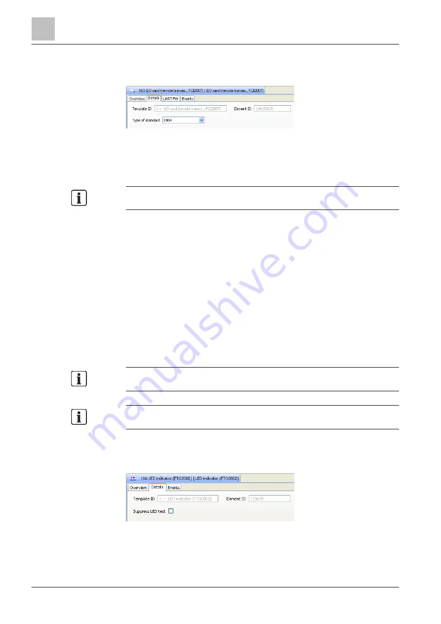
Figure 42: Properties in the detail editor of the LED indicator
'Suppress LED test': This setting specifies, if during the LED test on the connected
'Station' an LED test is carried out on the LED indicator, too. If the 'Suppress LED
test' checkbox is activated, a LED test is not carried out on the LED indicator.


