Description of the device
17
Building Technologies
Fire Safety & Security Products
11.2008
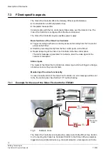
fire control panel via the FDnet. The fire control panel then sends a message via
the FDnet to the Video Fire Controller assigned to the particular peripheral device.
The images captured by the camera are then stored on the compact flash with a
predefined pre-event and post-event recording time.
The Video Fire Controller can be additionally connected to a CCTV system. See
Section 9.5: Connecting the
Video Fire Controller FDV241 to the FDnet and to the
CCTV system.
7.3.2
Diagnosis levels in FDnet
The Video Fire Controller is largely self-monitoring. The following diagnosis levels
are taken from the various check measurements:
z
Normal
z
Observe information
z
Exchange recommended
z
Exchange required
z
Fault
See Section 13: Trouble shooting.
Status request
The Video Fire Controller is equipped with an MC-link (maintenance and
commissioning link). With the detector exchanger and tester FDUD29x, the
following data can be displayed:
z
Inadmissible configuration
z
Error list
z
Status register
Functional check
The self-test function ensures that the Video Fire Controller is checked
automatically. It is nevertheless advisable to check the devices at regular intervals
on site:
z
Check the devices annually.
z
Replace all devices that are extremely soiled or damaged.
7.3.3
Degraded mode in FDnet
When the main processor of the fire control panel fails, the control panel is in
degraded mode. Depending on the control panel type, the fire control panel can
continue to perform the most important alarming and signalling functions in
degraded mode.
The degraded operation on the FDnet is not equally supported by all control
panels. During project planning, the information in the document 'List of
compatibility' (doc. no. 008331) and the control panel documentation in account is
mandatory.
The Video Fire Controller is not activated when the system is running in degrade
mode.


