FDCL221-MMulti line separator module
Technical Manual
A6V10224006_g_en_--
Building Technologies
2018-10-25
Control Products and Systems
Страница 1: ...FDCL221 M Multi line separator module Technical Manual A6V10224006_g_en_ Building Technologies 2018 10 25 Control Products and Systems ...
Страница 2: ...mmunication thereof to others without express authorization are prohibited Offenders will be held liable for payment of damages All rights created by patent grant or registration of a utility model or design patent are reserved Issued by Siemens Switzerland Ltd Building Technologies Division International Headquarters Theilerstrasse 1a CH 6300 Zug Tel 41 58 724 2424 www siemens com buildingtechnol...
Страница 3: ...rview 17 3 2 2 Printed circuit board view 18 3 2 3 Indication elements 18 3 2 4 Adjustment elements 19 3 3 Function 19 3 4 Behaviour in degraded mode 21 3 5 Accessories 22 3 5 1 Mounting foot FDCM291 22 3 5 2 U rail TS35 22 3 5 3 Housing FDCH221 23 3 5 4 M20 x 1 5 metal cable gland 23 3 5 5 M20 x 1 5 metal counter nut 23 3 5 6 Connection terminal DBZ1190 AB 24 4 Planning 25 4 1 Compatibility 27 4 ...
Страница 4: ...gies A6V10224006_g_en_ Fire Safety 2018 10 25 4 42 6 Commissioning 34 7 Maintenance Troubleshooting 35 8 Specifications 36 8 1 Technical data 36 8 2 Dimensions 39 8 3 Environmental compatibility and disposal 39 Index 40 ...
Страница 5: ...installation work Incorrect installation can take safety devices out of operation unbeknown to a layperson Goal and purpose This document contains all information on the multi line separator module FDCL221 M Consistent compliance with the instructions guarantees correct and safe use Intended use The line separator FDCL221 M may only be used for short circuit and open line monitoring in one of the ...
Страница 6: ...ents Checks operability and approves the product for commissioning at the place of installation Is responsible for troubleshooting Has obtained suitable specialist training for the function and for the products Has attended the training courses for Product Engineer Installation personnel Assembles and installs the product components at the place of installation Carries out a performance check foll...
Страница 7: ...n reproduced identically Key Identification of keys Relation sign and for identification between steps in a sequence e g Menu bar Help Help topics Text Identification of a glossary entry Supplementary information and tips The i symbol identifies supplementary information and tips for an easier way of working 1 1 Applicable documents Document ID Title 008331 List of compatibility for Sinteso produc...
Страница 8: ...search field You will also find information about search variants and links to mobile applications apps for various systems on the home page 1 3 Technical terms Term Explanation ABS Acrylonitrile butadiene styrene plastic FDnet C NET Addressable detector line Jumper Jumper on printed circuit board for configuration Collective detector line Non addressed detector line LED Light emitting diode Loop ...
Страница 9: ...d of a if the reference document is already this version The table below shows this document s revision history Version Edition date Brief description g 2018 10 25 Editorial changes f 2018 01 10 DBZ1190 AB Conductor cross section updated 0 5 2 5 mm2 Changes to Technical data chapter e 2016 04 20 Data sheet updated in Applicable documents chapter Document fully revised d 04 2010 LPCB number added c...
Страница 10: ... consequences measures and prohibitions examples of which are shown in the following table General danger Explosive atmosphere Voltage electric shock Laser light Battery Heat Signal word The signal word classifies the danger as defined in the following table Signal word Danger level DANGER DANGER identifies a dangerous situation which will result directly in death or serious injury if you do not a...
Страница 11: ...ry is shown as follows WARNING Nature and origin of the danger Consequences if the danger occurs Measures prohibitions for danger avoidance How possible damage to property is presented Information about possible damage to property is shown as follows NOTICE Nature and origin of the danger Consequences if the danger occurs Measures prohibitions for danger avoidance ...
Страница 12: ...idance and supervision of a qualified electrician in accordance with the electrotechnical regulations Wherever possible disconnect products from the power supply when carrying out commissioning maintenance or repair work on them Lock volt free areas to prevent them being switched back on again by mistake Label the connection terminals with external voltage using a DANGER External voltage sign Rout...
Страница 13: ...al for activation this is generally the potential of the building installation Only check controls up to the interface relay with blocking option Make sure that only the controls to be tested are activated Inform people before testing the alarm devices and allow for possible panic responses Inform people about any noise or mist which may be produced Before testing the remote transmission inform th...
Страница 14: ...tandards and directives complied with A list of the standards and directives complied with is available from your Siemens contact 2 4 Release Notes Limitations to the configuration or use of devices in a fire detection installation with a particular firmware version are possible WARNING Limited or non existent fire detection Personal injury and damage to property in the event of a fire Read the Re...
Страница 15: ... collective detector lines to the Sinteso Cerberus fire detection system with the FDnet C NET bus system Properties Compatible with fire detection system FS20 FS720 and FC360 Communication via the detector line Individual addressing of line separators for easy location identification Number of FDnet C NET loops can be configured using jumpers 9 line separators in one FDnet C NET loop or 2 x 4 line...
Страница 16: ...ou will find information on permissible topologies in fire detection systems FS20 FS720 in the 008843 for Sinteso and A6V10210362 for Cerberus PRO documents in the Line separation function chapter You will find this information for the fire detection system FC360 in document A6V10421795 Mounting Installation in intermediate distributor or directly in a fire control panel Mounting directly on a U r...
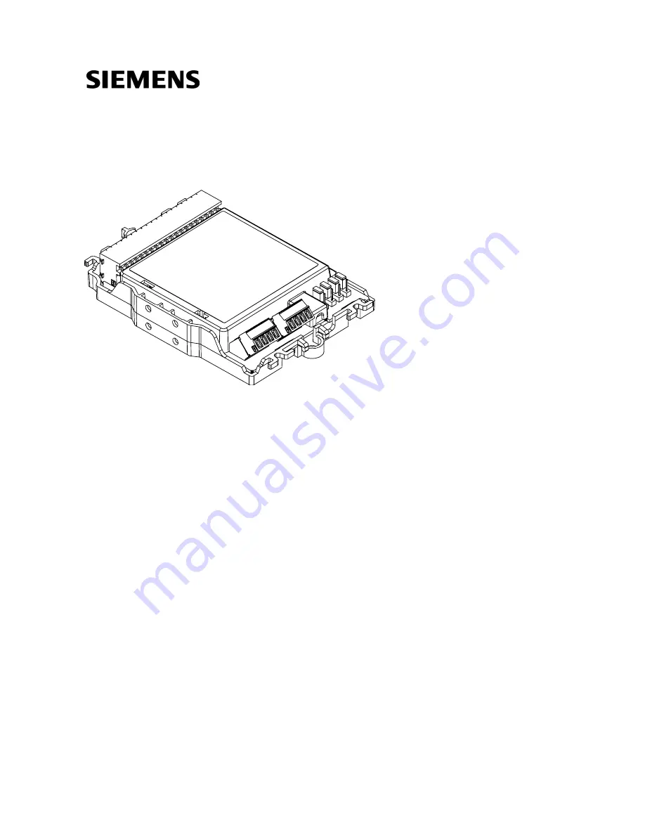
Страница 17: ...re 2 Overview of multi line separator module 1 Connector 20 pin for sub stub lines 5 Screw terminal for FDnet C NET detector line LINE 2 2 Module carrier 6 Screw terminal for FDnet C NET detector line LINE 1 3 Holes for mounting feet 7 Cable tie holder 4 Jumpers J1 J4 8 Mounting holes for screws 3 2 3 4 5 6 7 7 1 7 7 8 8 3 3 ...
Страница 18: ...tor line LINE 2 3 LED line separator 3 12 Screw terminal for FDnet C NET detector line LINE 1 4 LED line separator 4 13 Connector 20 pin for sub stub lines 5 LED line separator 5 6 LED line separator 6 7 LED line separator 7 8 LED line separator 8 9 LED line separator 9 3 2 3 Indication elements Each line separator has a status indicator The yellow LED flashes if the line separator is open or in l...
Страница 19: ...e separator in the FDnet C NET loop is to connect sub stub lines to the FDnet C NET and selectively disconnect them in the event of a short circuit In the event of a short circuit the line separator disconnects the affected bus area in the FDnet C NET so that the area unaffected by the short circuit continues to function The multi line separator module has 2 x 4 screw terminals for the FDnet C NET...
Страница 20: ... module is connected to a FDnet C NET loop This is the default configuration of the multi line separator module when delivered Figure 4 FDCL221 M topology with one detector line loop 1 1 First sub stub on FDnet C NET loop Ts FDnet C NET device on sub stub 2 5 Tenth last sub stub on FDnet C NET loop Tr FDnet C NET device on FDnet C NET loop ...
Страница 21: ...e on FDnet C NET loop See also 2 Printed circuit board view 18 2 Indication elements 18 2 Adjustment elements 19 3 4 Behaviour in degraded mode Applicable for the FDnet C NET When the main processor of the fire control panel fails the control panel works in degraded mode operation Depending on the control panel type the fire control panel can continue to perform the most important alarming and sig...
Страница 22: ...A1209 Z1 Multi line separator module FDCL221 M Zone module external powered FDCI223 FDCI723 Sounder module FCA2005 A1 Order number A5Q00003855 3 5 2 U rail TS35 Standard DIN rail for installing devices Width 35 mm Length 122 mm or 288 mm Compatible with Various input output modules Line separator FDCL221 Mounting foot FDCM291 Line adapter Ex FDCL221 Ex Sounder module FCA2005 A1 Order number length...
Страница 23: ...r number S54312 F3 A1 See also 2 Mounting with housing FDCH221 31 3 5 4 M20 x 1 5 metal cable gland For introducing a cable into a housing For cable diameters of 3 5 5 5 mm Temperature range 40 100 C Allows for increased IP protection Compatible with M20 x 1 5 metal counter nut Housing FDMH231 S R Housing FDMH292 x Housing FDMH293 x Housing FDMH297 R Housing FDCH221 Manual call point FDM243H Air s...
Страница 24: ...018 10 25 3 5 6 Connection terminal DBZ1190 AB Auxiliary terminal for connecting cables For T branches of additional cabling e g for cable shielding detector heating units sounder base external alarm indicators etc For conductor cross sections of 0 5 2 5 mm 3 poles Order number BPZ 4942340001 ...
Страница 25: ...ies one bus address and is visible in the line topology Rules for the branching of a sub stub from a loop Only one sub stub is permitted between two FDnet C NET devices One sub stub is permitted at the start and end of the loop respectively between the connection terminals of the fire control panel and the first line device If there is more than one sub stub between two FDnet C NET devices a line ...
Страница 26: ...t floors Figure 7 FDCL221 M 1 loop operation or 2 loop operation assembled in an intermediate distributor 1 Intermediate distributor 1 1 First sub stub on FDnet C NET loop 1 2 FDnet C NET loop 2 5 Fifth sub stub on FDnet C NET loop 2 Ts FDnet C NET device on sub stub 1 n Nth sub stub on FDnet C NET loop 1 Tr FDnet C NET device on FDnet C NET loop 2 n Nth sub stub on FDnet C NET loop 2 ...
Страница 27: ...wer software the FDCL221 M identifies itself with the following combination Product version ES 2 Software version Software version 60 This combination is intended for the FDCL221 M for compatibility reasons It does not indicate a device defect You will find more detailed information in the fire detection system documentation 4 2 Fields of application The line separator is required in a FDnet C NET...
Страница 28: ...re used in industrial applications consultation with the project manager is required since plastics do not withstand certain environmental conditions The following factors must be taken into consideration Chemicals Temperature Moisture The housing is made from plastic and the printed circuit board is sealed with wax for increased corrosion protection ...
Страница 29: ... feet vertically on a U rail TS35 With two mounting feet horizontally on a U rail TS35 Proceed as follows to mount the multi line separator module 1 Mount the multi line separator module on a flat surface with 2 screws or with two mounting feet on a U rail see following figures Pick a suitable position during mounting to ensure that the LEDs are visible at all times 2 Connect the cables to the ter...
Страница 30: ... 2 Installation and connection diagram 32 5 2 Removing from the U rail Proceed as follows to remove the multi line separator module from the U rail 1 Place a screwdriver at a right angle between the mounting foot and the mounting surface of the U rail 2 Turn screwdriver to release mounting foot Figure 10 Removing the multi line separator module from a U rail 1 Screwdriver size 4 1 ...
Страница 31: ...or module in housing FDCH221 1 Break open required cable entries on housing 2 Install housing on a flat surface 3 Insert cables If necessary fasten the cables using the M20 x 1 5 cable glands or use a different cable entry 4 Install multi line separator module in housing with enclosed fixing screws 5 Connect cables to corresponding terminals see Installation and connection diagram 32 6 Close housi...
Страница 32: ...fety 2018 10 25 5 4 Installation and connection diagram Specialist electrical engineering knowledge is required for installation Only an expert is permitted to carry out installation work Incorrect installation can take safety devices out of operation unbeknown to a layperson Figure 12 FDCL221 M connection diagram ...
Страница 33: ...rnal ground potentials or metal parts Secure cables on module carrier with cable ties Only connect one sub stub between two FDnet C NET devices If you need to connect more than one sub stub always connect a line separator between the sub stubs Press orange contact opening with screwdriver width of blade 2 5 mm when inserting wire into socket strip Press orange contact opening with screwdriver to l...
Страница 34: ...odule FDCL221 M is a line participant which depending on the operation mode occupies up to nine bus addresses and is visible in the line topology Each individual line separator has its own bus address The device is commissioned via the control panel The exact procedure is described in the control panel documentation Conduct a performance check once commissioning is complete ...
Страница 35: ...ng 7 35 42 Building Technologies A6V10224006_g_en_ Fire Safety 2018 10 25 7 Maintenance Troubleshooting The multi line separator module is maintenance free It features a self monitoring function and must be replaced if damaged ...
Страница 36: ...pter Document A6V10230308 Detector line Operating voltage DC 12 33 V Quiescent current 1 loop operation 2 25 mA 9 x 250 µA 2 loop operation 2 x 1 mA 4 x 250 µA Quiescent current connection factor Per line separator 1 1 loop operation Max 9 x 1 2 loop operation Max 2 x 4 Address connection factor 1 loop operation 9 x 1 2 loop operation 2 x 4 Separator connection factor Per line separator 1 1 loop o...
Страница 37: ...hes are closed Max 0 4 Ω ZC max When operated on the FDnet C NET the line separator is closed via an actuation signal from the control panel Required line voltage DC 12 33 V normal range External alarm indicators Number of external alarm indicators that can be connected None Connections Detector line Design Screw terminals on plug Cable cross section 0 2 1 5 mm2 Bare length 6 mm Sub stubs Design S...
Страница 38: ...data Dimensions L x W x H Module FDCL221 M without housing 132 x 90 x 24 mm Housing FDCH221 207 x 119 x 50 mm Weight of module FDCL221 M 0 124 kg Housing material ABS Colors Module carrier RAL 9010 pure white Housing FDCH221 RAL 9010 pure white Housing cover Transparent matt Standards European standards EN 54 17 ...
Страница 39: ...ore specifically the following measures have been undertaken Use of reusable materials Use of halogen free plastics Electronic parts and synthetic materials can be separated Larger plastic parts are labeled according to ISO 11469 and ISO 1043 The plastics can be separated and recycled on this basis The device is considered an electronic device for disposal in accordance with the European Guideline...
Страница 40: ...nter URL 8 E Electronic switch Line separator 15 Environmental compatibility 39 Environmental influences 28 EU directives 36 F FDnet C NET Detector line protocol 15 Fire control panel failure Degraded mode operation 21 I Impact Chemicals 28 Moisture 28 Temperature 28 Intended use 5 J Jumper Configuration 19 L Labeling of system documentation Tear off label 33 LED Line separator status indicator 18...
Страница 41: ...Index 41 42 Building Technologies A6V10224006_g_en_ Fire Safety 2018 10 25 ...
Страница 42: ...on International Headquarters Theilerstrasse 1a CH 6300 Zug 41 58 724 2424 www siemens com buildingtechnologies Siemens Switzerland Ltd 2009 Technical specifications and availability subject to change without notice Document ID A6V10224006_g_en_ Edition 2018 10 25 ...