Copyright © Siemens AG 2016. All rights reserved
233
ERTEC 200P-2 Manual
Technical data subject to change
Version 1.0
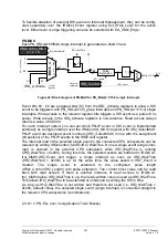
The PN-PLL contains a clock instance (Clock_A), a time instance and 3 application timer
blocks. Each application timer block controls its own application cycle and is connected to
the Clock_A instance. The application clock (APPL1/2/3_CLK_INT) and 6 programmable
phase signals (APPL1/2/3_ CMP_INT5...0) are available as outputs for each application
timer block. These 21 outputs are connected to a 21-input multiplexer
(PNPLL_OUT20...0). Any output of the 3 application timer blocks can be selected at each
MUX output. The controlled clock of the clock instance (PNCLKA_OUT) can also be
connected to the MUX outputs.
Figure 24 shows how these outputs (PNPLL_OUT20...0) are connected to the application
instances at the ERTEC 200P top level.
Figure 25: PNPLL with 3 application time blocks (application connection)
The connection matrix is as follows:
GPIO
ARM-
ICU
GDMA
PNPLL0 GPIO0_INT
PNPLL1 GPIO1_INT
PNPLL2 GPIO2_INT
PNPLL3 GPIO3_INT
PNPLL4 GPIO4_INT
PNPLL5 GPIO5_INT
PNPLL6 GPIO6_INT
PNPLL7 GPIO7_INT
PNPLL8 GPIO8_INT
PNPLL9
IRQ72
PNPLL10
IRQ73
PNPLL11
IRQ74 HWJob(0)
PNPLL12
IRQ75 HWJob(1)
PNPLL13
IRQ76 HWJob(2)
PNPLL14
IRQ77 HWJob(3)
PNPLL15
HWJob(4)
PNPLL16
HWJob(5)
PNPLL17
HWJob(6)
PNPLL18
HWJob(7)
PNPLL19
HWJob(8)
PNPLL20
HWJob(9)
Содержание ERTEC 200P
Страница 1: ...ERTEC 200P 2 Enhanced Real Time Ethernet Controller Manual ...
Страница 309: ...Copyright Siemens AG 2016 All rights reserved 309 ERTEC 200P 2 Manual Technical data subject to change Version 1 0 ...
Страница 492: ...Copyright Siemens AG 2016 All rights reserved 492 ERTEC 200P 2 Manual Technical data subject to change Version 1 0 ...

