background image


Document No:  IOM-002 


Issue Date: 

24/09/2020


Revision:


Page:


18 of 42 


Unrestricted 


SPECIFICATIONS 

The  following  is  a  basic  specification  for  DigiTRON  connectors.  Actual  product  may  vary.  Please 
refer to product specific data sheet(s), website


https://www.siemens-energy.com

 /search Subsea, or 

contact  Siemens  Energy  Technical  Support 

[email protected]


for more detailed information. 

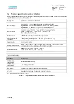
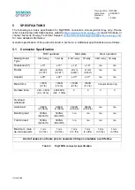
General specification of the product is listed in section 2.2. Additional specifications are as follows. 

5.1 

Connector Specification 


ROV operated 

Stab-plate 

Diver operated 

Misalignment 
Type 

4 & 7-way 

12-way 

4 & 7-way 

12-way 

4 & 7-way  12-way 

Rotational (0º) 

±15º 

±15º 

±1.6º 

±1.6º 

n/a 

n/a 

Radial 

±20mm 

(0.787”) 

±20mm 

(0.787”) 

±1mm 

(0.039”) 

±1mm 

(0.039”) 

n/a 

n/a 

Angular 

±20º 

±20º 

±0.7º 

±0.7º 

n/a 

n/a 


Mate force 

<300N 

(67 lb) 

<500N 

(112 lb) 

<300N 

(67 lb) 

<500N 

(112 lb) 

Integral clamp ring 

Demate force 

240 

– 360N 

(54 

– 81 lb) 

480-800N 

(108 - 179lb) 


Overload 
withstand 


Axial load 

9800N 

(2,198 lb) 

9800N 

(2,198 lb) 

9800N 

(2,198 lb) 

9800N 

(2,198 lb) 

n/a 

n/a 

Bending load 

500Nm 

(369 lbf.ft) 

500Nm 

(369 lbf.ft) 

n/a 

n/a 

n/a 

n/a 

Torsion load 

500Nm 

(369 lbf.ft) 

500Nm 

(369 lbf.ft) 

n/a 

n/a 

n/a 

n/a 


Maximum  mate  /  
de-mate speeds 

1 m/s 

(3.3 ft/s) 

1 m/s 

(3.3 ft/s) 

1 m/s 

(3.3 ft/s) 

1 m/s 

(3.3 ft/s) 

1 m/s 

(3.3 ft/s) 

1 m/s 

(3.3 ft/s) 


Limit of exposure of male pins to seawater


28 days cumulative over lifetime


Table 5 

DigiTRON connector specification 


Содержание DigiTRON Series

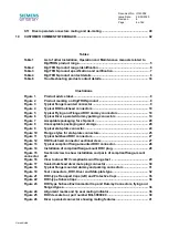
Страница 1: ... dd mm yyyy Revision 1 Page 1 of 42 Unrestricted CONTROLLED COPY DigiTRON Single Connectors Installation Operations and Maintenance Manual Protection Storage Shipment Unpacking Deployment Maintenance Instructions Document No IOM 002 ...

Страница 2: ...bria LA12 9EE England Rev Compiled by Date Approved by Issue Date Page s Affected Remarks 6 R Wyatt 26 06 2020 E Chaize 26 06 2020 Updated onto new IOM template with product safety advice clearly identified DigiTRONe and DigiTRON3 added Section on Caps and Dummies added Alternative test connector added from IOM 002 CAM so this IOM can be obsoleted 5 R Wyatt 21 02 2020 J Hardisty 21 02 2020 Safety ...

Страница 3: ...ODUCT FOR USE OR STORAGE 20 6 1 Product protection and packaging 20 6 2 Unpacking 21 6 3 Storage protection and end of life 21 7 INSTALLATION AND ASSEMBLY 23 7 1 Cathodic protection 23 7 2 Installation equipment 23 8 USER INFORMATION DURING NORMAL OPERATION AND FAULT CONDITIONS 33 8 1 Visible audible signals 33 8 2 Normal and faulty dangerous operation 33 8 3 Troubleshooting 33 9 PRODUCT OPERATION...

Страница 4: ...cceptable packaging and storage 20 Figure 9 Typical stab plate connector 24 Figure 10 Flange styles for stab plate connectors 25 Figure 11 Typical bulkhead ROV connectors 27 Figure 12 ROV bulkhead connector sectional view 27 Figure 13 Typical compliant flange mounted ROV connector 28 Figure 14 Installation of compliant flange mount ROV plug 28 Figure 15 Sectional view to show installation and part...

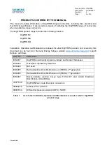
Страница 5: ...his document can be found on Siemens Energy Subsea website www siemens energy com search Subsea as follows DOC No PRODUCT IOM 001 DigiTRON electrical flying leads Jumper and Sensor Harnesses IOM 003 Obsoleted replaced by IOM 002 IOM 004 Not used IOM 005 Retrievable Electrical Distribution unit REDU 2nd generation IOM 006 Retrievable Electrical Distribution unit REDU 1st generation IOM 007 Disconne...

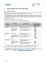
Страница 6: ...ion Visual identifier Typical part number etched on the connector DigiTRON 4 7 and 12 pins Voltage rating 1kV pin ground 2kV pin pin White coloured cone or disc on ROV connectors No visual identifier on Stab or Diver type connectors BROV BRSP BSTA BSSP BDIV BDSP DigiTRONe 12 pins only As DigiTRON but with 4 or 8 of the pins wired with ethernet cable White coloured cone or disc on ROV connectors No...

Страница 7: ...7 way 14A 12 way 11A Excludes ethernet lines Over current 100A for 5 seconds no more than 2 per hour Rated number of operations 1000 750dry 250wet mate de mate cycles Power off Water depth 4 000 m 13 123ft Storage temperature 40 C 70 C 40 F 158 F upper limit is surface temperature of the product and includes solar gain from bright sunlight Operational temp Subsea 5 C 60 C 23 F 140 F In air 20 C 50...

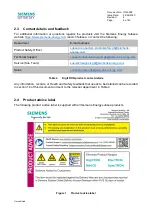
Страница 8: ...uctsafety gb siemens energy com Technical Support connectortechnicalsupport gb siemens energy com Service Site Team susultlcmsupport gb siemens energy com Sales connectorsales gb siemens energy com Table 4 DigiTRON product contact details Any information records or Health and Safety feedback that needs to be detailed can be recorded in section 10 of this document and sent to the relevant departmen...

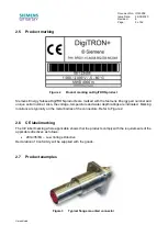
Страница 9: ...lso the voltage temperature and water depth ratings are indicated Marking locations are typically on the metal bodies of the connectors Refer to Figure 2 2 6 CE label marking The CE label marking where applicable shows that the products comply with the requirements of the applicable directives as follows 2014 35 EU Low Voltage Directive Declaration of Conformity will be supplied with the goods 2 7...

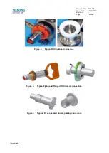
Страница 10: ...002 Issue Date 24 09 2020 Revision 6 Page 10 of 42 Unrestricted Figure 4 Typical ROV bulkhead connectors Figure 5 Typical Flying and Flanged ROV dummy connectors Figure 6 Typical Diver operated dummy parking connectors ...

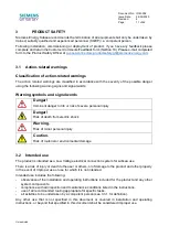
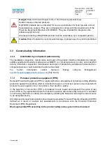
Страница 11: ...nent danger to life or risk of severe personal injury Danger Risk of death from electric shock Warning Risk of minor personal injury Caution Risk of material or environmental damage 3 2 Intended use The product is intended as a Low Voltage electrical connection system for subsea use There is a risk of injury or death to the user or others or of damage to the product and other property in the event...

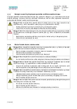
Страница 12: ... repair of products by untrained and deemed non competent persons could invalidate the product warranty For further information contact Siemens Energy Lifecycle Management susultlcmsupport gb siemens energy com Site Team Personal protective equipment PPE Personal Protective Equipment PPE is legally defined as all equipment including clothing affording protection against the weather which is intend...

Страница 13: ...p side system test and unmated receptacle is energised Never energise a receptacle connector when not mated to a plug Ensure all test procedures are followed Communication channels and protocols are observed Danger Risk of death from electric shock due to unscreened cables Do not touch electrical wires while energised Ensure all test procedures are followed Danger Risk of death from electric shock...

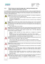
Страница 14: ...ssure test or the rated differential pressure of the product is exceeded Ensure all product assembly and testing activities are completed by competent persons Do not exceed the maximum differential pressure rating of the product installed Individual products have different differential pressure ratings refer to the specific product datasheet or contact Siemens Energy Technical Support Warning Risk...

Страница 15: ...odily injury from heavy product falling during lift with machinery Ensure machinery slings used have been tested and are within their expiry date Safe lifting guidelines must be followed e g lifting plan banksman etc Correct lifting points must be identified and used Only competent persons are permitted to perform tasks without supervision if in doubt ask Warning Risk of minor personal injury to p...

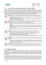
Страница 16: ...practice such as the following The Health and Safety at Work Act COSHH Control of substances hazardous to health BS 7671 Requirements for electrical installations IEE Wiring Regulations The Electricity at Work Regulations It is the operator s and installers responsibility to comply with current Company area regional national or international health and safety legislation 3 5 Control of substances ...

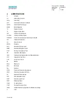
Страница 17: ...athodic Protection dc Direct Current DWG Drawing EFL Electrical Flying Leads EMF Electrical Magnetic Field FAT Factory Acceptance Test IR Insulation Resistance ISO International Organization for Standardization ITP Inspection Test Plan LTC Long Term Cover M Metres Max Maximum Min Minimum No Number PPE Personal Protective Equipment ROV Remotely Operated Vehicle SI Standard International SIT Site In...

Страница 18: ...gnment Type 4 7 way 12 way 4 7 way 12 way 4 7 way 12 way Rotational 0º 15º 15º 1 6º 1 6º n a n a Radial 20mm 0 787 20mm 0 787 1mm 0 039 1mm 0 039 n a n a Angular 20º 20º 0 7º 0 7º n a n a Mate force 300N 67 lb 500N 112 lb 300N 67 lb 500N 112 lb Integral clamp ring Demate force 240 360N 54 81 lb 480 800N 108 179lb 0 0 0 0 Overload withstand Axial load 9800N 2 198 lb 9800N 2 198 lb 9800N 2 198 lb 98...

Страница 19: ...e contact surfaces of the receptacle contact pins This could lead to damage to the seals and insulation within the plug socket contacts Plug connectors do not require full dummy connectors for protection Siemens Energy Subsea advise the fitting of acetal caps to protect plugs against marine growth It is good practice to always fit the protective cap when a connector is unmated topside prior to dep...

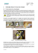
Страница 20: ...ors can be shipped singularly or in multiples Care should be taken to protect the connector s with Instapack bubble wrap or similar wrapping materials to avoid surface damage during transit If large numbers are shipped in one consignment suitably reinforced transport box will be necessary to withstand the weight See Figure 7 and Figure 8 Figure 7 Acceptable packaging for shipment Figure 8 Unaccept...

Страница 21: ... clean water to remove any saltwater on the products Short term storage Prior to installation the connectors are sensitive to environments where grit and dirt are present To prevent ingress of the above they should be stored in a clean dry area and be protected by bubble wrap or similar wrapping material Transport protective caps must be fitted Connectors supplied in boxes should be stored in the ...

Страница 22: ...vent of a requirement to return any product back to the manufacturer Siemens Energy Subsea Connectors it is recommended that the transport cap protective cap or suitable dust cap is fitted to the connector s and care should be taken to protect the connector s with bubble wrap or similar wrapping materials to avoid any surface damage If there are multiple connectors to be returned it is recommended...

Страница 23: ...he connector from the structure to which it will be mounted ROV connectors that do get connected to the CP system will not be immediately damaged but there is an increased risk of hydrogen embrittlement of the metal possible cracking under high mechanical stresses and increased rate of calcareous deposits on the product which may cause problems demating the connectors Stainless steel 316L UNS S316...

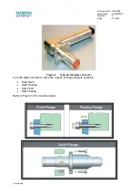
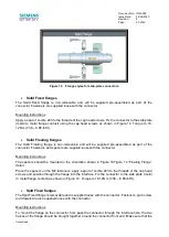
Страница 24: ...0 Revision 6 Page 24 of 42 Unrestricted Figure 9 Typical stab plate connector For stab plate connectors there are 4 types of flange designs available Solid Fixed Solid Floating Split Fixed Split Floating Refer to Figure 10 for mounting detail ...

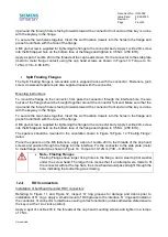
Страница 25: ...nector Fasteners and spacers are supplied loose with the connector Mounting instructions The spacers should be mounted in the orientation shown in Figure 10Figure 14 Floating Flange detail Place the spacers on the M6 fasteners apply a spot of Loctite 243 to the threads of the cap head screws and position through the flange into the interface Fix the connector to the stab plate metal to metal flang...

Страница 26: ...e two halves together Insert the 2 off location dowels into the holes in the flange and press fit until flush with the face of the flange A M6 grub screw is supplied for tightening the flange to the connector body Apply Loctite 243 screw into the M6 tapped hole on the bottom face of the flange and tighten to 3 5 Nm 2 58 lbf ft The spacers should be mounted in the orientation shown in Figure 10Figu...

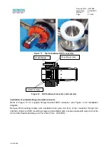
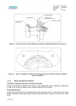
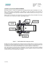
Страница 27: ...ed connector Refer to Figure 13 for a typical flange mounted ROV connector and Figure 14 for installation diagram Remove M6 mounting screws and orientation disc pass the front of the connector through the interface install 4 off M6 mounting screws and orientation disc secure screws with a spot of Loctite 243 on the threads and torque to 10 12 Nm 7 38 8 85 lbf ft Acetal flange Install O rings Mount...

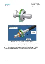
Страница 28: ... male pins an extra ring is required to keep the connector captive in the event that the rubber mount is lost This is supplied with the connector and should be fitted along with the alignment disc in the orientation shown in Figure 15 and Figure 16 NOTE The alignment cone on the receptacle may require removal in order to install the connector and re fitting once installed Ensure correct orientatio...

Страница 29: ...ptacle Diver operated connectors Installation of flange mounted diver operated connectors Flange mounted diver operated connector have a fixed flange that will be supplied pre assembled as part of the connector Fasteners are supplied loose with the connector Mounting instructions Apply a spot of Loctite 243 to the threads of the cap head screws Fix the connector to the mounting position metal to m...

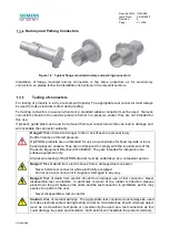
Страница 30: ... ft for metal to metal flange contact Figure 17 Sealed bulkhead diver mate plug connector Bulkhead connectors with pigtail wires terminated should be treated with care especially around the termination area and the termination area should not be bent Excessive force should not be used to pull the wires The connector should not be held or carried using the terminated wires Care must be taken to pro...

Страница 31: ...nded for use as a penetration for fixed top side or land based pressure vessels They are not designed to comply with the requirements of the Pressure Equipment Directive 2014 68 EU They are intended for integration into subsea equipment only All pressure testing of DigiTRON product must be undertaken by a competent person Danger Risk of death from electric shock from a damaged test connector Never...

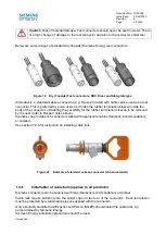
Страница 32: ...iminating the possibility for the rubber termination sleeves to be removed by the user refer to Danger notes above Siemens can provide such connectors tailed with appropriate cables Siemens recommendation or untailed See section 7 2 6 for instruction on installing cable tails Figure 20 Example of standard subsea connector shown untailed Installation of cable tails applies to all products Siemens c...

Страница 33: ...r from the oil filled hoses or junction boxes Bent pins Blackening or darkening of the rubber seals on the front face of the plug Any signs of electrical activity on the exterior of the products such as burning on the front face of the plug or burning of the male pins Green coloured corrosion on the male pins Damaged insulation on any cables Loose or faulty electrical joint between cables and conn...

Страница 34: ...lative allowable exposure of unprotected receptacle pins to seawater over the lifetime of the connector Always immediately fit a Subsea Environment Cap or Dummy Plug to the receptacle in order to protect the pins from corrosion Caution Risk of material damage Under no circumstances must the contact pins in the receptacle connector be exposed to seawater with power on If this situation does occur t...

Страница 35: ...des mechanical protection to the plug or receptacle connector Figure 22 It is a non electrical cap The cap for the plug connector female sockets oil filled can be used for long term mechanical protection The cap for the receptacle exposed male pins does not protect the exposed male pins in the receptacle from corrosion It should only be used for very short term subsea use e g the cap is removed wi...

Страница 36: ... Caution Risk of material damage The maximum number of live mate de mate operations under any of these conditions is ONE only There is a high risk of damage to both plug and receptacle connector that would render it unusable Resistive loads Mating the connectors should not lead to any damage to the sealing mechanisms within the plugs Following this de mating procedure testing should be carried out...

Страница 37: ...efore mating the product Transport and topside protection caps must be removed before subsea deployment Before mating the receptacle connector male pins should be checked for debris and damage The connectors have been designed to accommodate sand and silt contamination however large pieces of debris should be removed Use a water jet if subsea but do not direct the water jet at the front face seals...

Страница 38: ...in Figure 24 If the lip seal can still be seen remove and retry making connection by following the procedure again If connectors can t be mated both the plug and receptacle need to be inspected for any mis alignment damage or debris that is preventing connection If any damage has occurred please contact Siemens Energy Technical Support for advice ROV connector maximum misalignment values and matin...

Страница 39: ...e the latching mechanism Force required is detailed under the mechanical forces in section 5 1 For topside use e g during system testing there is a hand operated ROV de mate tool available to make connector de mate by hand easier and safe It is recommended that this tool should always be used topside Part number BQ 30090 00 See Figure 25 Figure 25 ROV de mate tool part number BQ 30090 00 Warning R...

Страница 40: ...he primary seals within the plug There is also an increased risk of insulation break down at voltages above 500V Interrupted connection i e Partial mate to full de mate can be carried out without any adverse effect to connectors as long as the power is off 9 11 Diver operated connectors mating and de mating Diver operated connector mating and de mating The clamp ring should be rotated clockwise by...

Страница 41: ...Document No IOM 002 Issue Date 24 09 2020 Revision 6 Page 41 of 42 Unrestricted Figure 26 Diver operated connector showing mating features ...

Страница 42: ...roject Reference Customer Region Product Type Part Number P N Serial Number S N Please enter details below e g comments complaints evidence of good practice incident reports observations and recommendations including any associated with health safety or the environment etc also include any names contact details of other relevant personnel Sign Off Section Name BLOCK CAPITALS Signature Date Please ...

Отзывы: