Diagnostics
6.3 Structure of the diagnostics frame
ASM 456 interface module
Operating Instructions, 07/2015, J31069-D0162-U001-A6-7618
47
6.3
Structure of the diagnostics frame
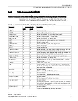
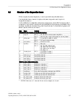
When using device-relate diagnostics, it can be evaluated using the table below.
The diagnostics frame consists of 6 bytes of standard diagnostics and 18 bytes of
diagnostics extension.
For the ASM 456, the diagnostics extension is designed as a status PDU for device-related
diagnostics. The structure complies with the PROFIBUS Profile Guideline (PROFIBUS Proxy
Guideline, Identification Systems Proxy Ident Function Block) for Identification Systems with
MOBY-specific additional information.
Byte
Name
Contents
PROFIBUS Profile Guideline for Identification Systems
6
sign_len
Bit 7..6
00b: Identifier for device-related diagnostics
Bit 5..0
010010b (18d): Length of the extension including header
7
status_type
Bit 7
1b: Identifier for status (0 = alarm)
Bit 6..0
1d: Type for status message
8
slot_number
Bit 7..0
0d: Device in total
9
specifier
Bit 7..2
Reserved
Bit 1..0
00b: No further differentiation
10b: Status inactive (outgoing)
01b: Status active (incoming)
11b: Reserved
10
channel_num
Bit 7..0
1d: Relating to reader 1
2d: Relating to reader 2
11
function_num
See Profile Guideline
12
error_decode
See Profile Guideline
13
error_code_1
See Profile Guideline
14
error_code_2
See Profile Guideline
MOBY-specific additional information
15
moby_code_1
MOBY error code byte 1
1)
16
moby_code_2
MOBY error code byte 2
1)
17
moby_code_3
MOBY error code byte 3
1)
18
moby_code_4
MOBY error code byte 4
19
meldecode
Error code for diagnostics messages (see GSD file)
20
counter_high
Continuous event counter high-order byte
21
counter_low
Continuous event counter low-order byte
22
fw_version_high
Firmware version high-order byte
23
fw_version_low
Firmware version low-order byte
1)
With FB 45 the value is = 0, because the error code is mapped only in byte 4.


