Installation Instructions
Document No. 129-420
December 13, 2004
OpenAir™ External Auxiliary Switch
a
b
c
d
e
f
g
EA1
175R1
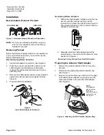
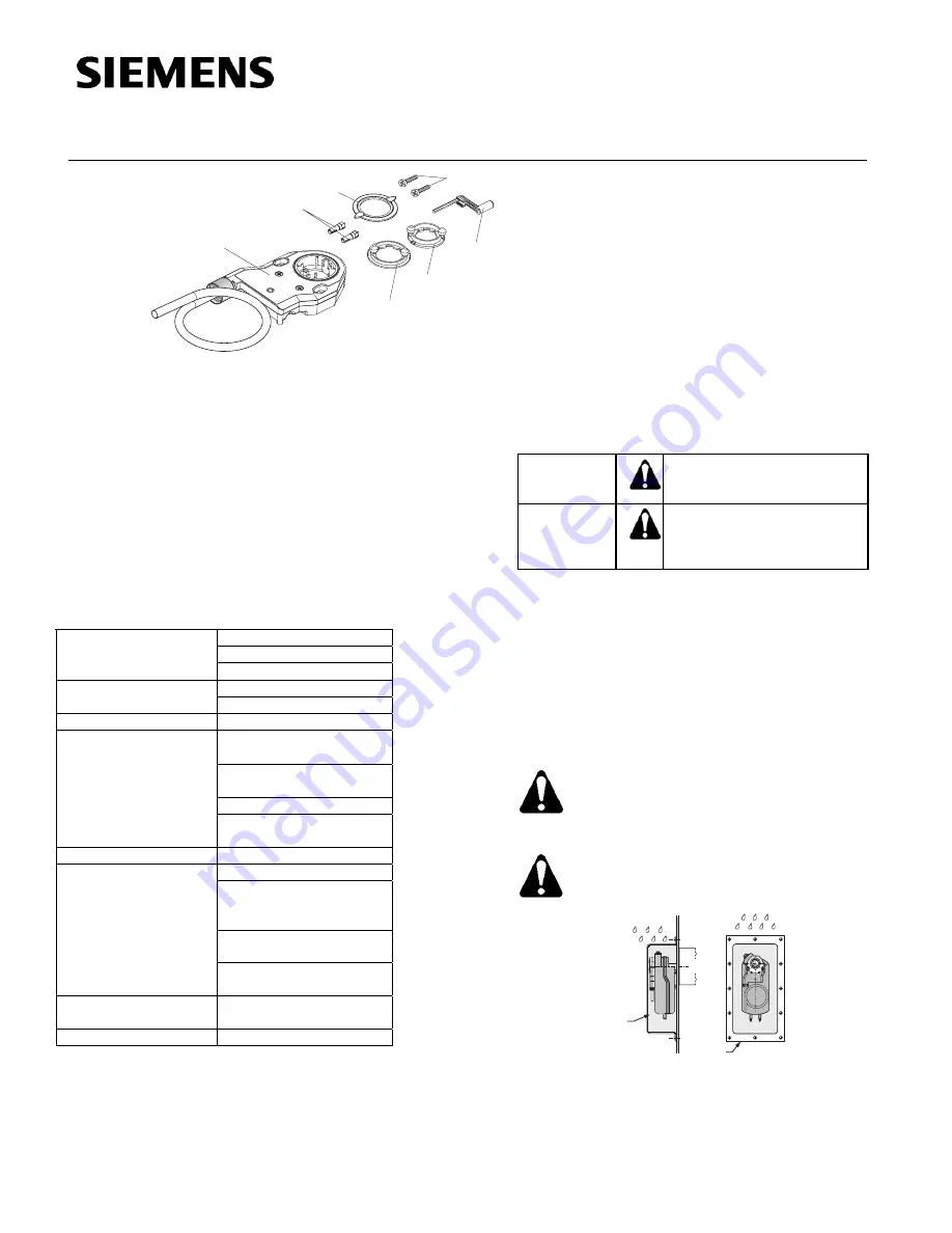
a. External dual auxiliary switch
b. Position
indicator
c. GCA/GBB/GIB position adapter
d. GMA/GEB position adapter
e. 3 mm hex key
f. Plastic mounting adapter inserts (2)
g. Threaded M5 × 25 screws (2)
Figure 1. External Auxiliary Switch Kit Contents.
Product Description
The OpenAir External Auxiliary Switch (EAS) provides
switch functionality for standard model damper actuators
with easy installation for in-service units.
Product Number
ASC77.2U
Specifications
Dual Auxiliary Switches
24 Vac to 250 Vac
AC 6A resistive
AC rating
AC 2 FLA, 12 LRA
12 Vdc to 30 Vdc
DC rating
DC 2A
Insulation system
Double insulated
Switch range
Switch
A
0° to 90° with 5° intervals
Recommended
usage
0° to 45°
Switch B
0° to 90° with 5° intervals
Recommended
usage
45° to 90°
Switching hysteresis
2°
UL listed to UL 873
cUL certified to Canadian
Standard C22.2
No. 24-93
Electromagnetic
compatibility 89/336/EEC
Agency certification
Low voltage directive
73/23/EEC
Conduit Connection
Threaded 1/2-inch
NSPT, flex only
Shipping Weight
1.1 lb (0.48 kg)
Warning/Caution Notations
WARNING:
Personal injury/loss of life
may occur if you do not follow
the procedures as specified.
CAUTION:
Equipment damage, or loss of
data may occur if you do not
follow the procedures as
specified.
Required Tools
Phillips screwdrivers
No. 2 for screws, No. 1 for adjustment
Expected Installation Time
15 minutes
Prerequisites
CAUTION:
Remove power from in-service damper
actuator before installing external
auxiliary switch.
WARNING
:
Do not open the external auxiliary switch.
EA1
191R1
ASK75.3U
or
ASK75.1U
ASK75.3U
or
ASK75.1U
Figure 2. NEMA Type 3R Rating Only
With Use of Weather Shield.
Item Number 129-420, Rev. 010
Page 1 of 5


