7SR210 & 7SR220 Description of Operation
Unrestricted Page 32 of 94
©2018 Siemens Protection Devices Limited
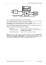
Minimum Polarising Voltage
The
67N Minimum Voltage
setting defines the minimum polarising voltage level. Where the measured polarising
voltage is below this level no directional output is given and operation of protection elements set as directional will
be inhibited. This prevents mal-operation under fuse failure/MCB tripped conditions where noise voltages can be
present.
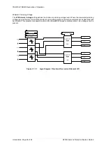
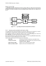
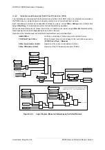
Figure 3.3.1-1
Logic Diagram: Derived Directional Earth Fault Element
3.3.2
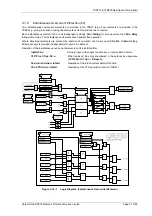
Instantaneous Derived Earth Fault Protection (50N)
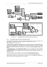
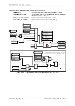
Two instantaneous derived earth fault elements are provided in the 7SR21 relay. Four elements are provided in
the 7SR22 relay e.g. giving the option of using two elements set to forward and two to reverse.
Each instantaneous element has independent settings for pick-up current
50N-n Setting
and a follower time
delay
50N-n Delay
. The instantaneous elements have transient free operation.
Where directional elements are present the direction of operation can be set using
50N-n Dir. Control
setting.
Directional logic is provided independently for each 50-n element.
Operation of the instantaneous earth fault elements can be inhibited from: -
Inhibit 50N-n
A binary input, virtual input, function key or remote data Comms.
79 E/F Inst Trips:
50N-n
When ‘delayed’ trips only are allowed in the auto-reclose sequence
(
79 E/F Prot’n Trip n
=
Delayed
).
50N-n VTSAction:
Inhibit
Operation of the VT Supervision function (7SR22).
50N-n Inrush Action:
Inhibit
Operation of the current inrush detector function.
Содержание Argus 7SR21
Страница 1: ...Energy Management 7SR21 7SR22 Argus Overcurrent Relay Reyrolle Protection Devices ...
Страница 2: ......
Страница 4: ...Contents 7SR11 and 7SR12 Page 2 of 2 2018 Siemens Protection Devices Limited ...
Страница 116: ...7SR210 Instrumentation Guide Unrestricted Page 4 of 12 2018 Siemens Protection Devices Limited 1 Function Diagram ...
Страница 117: ...7SR210 Instrumentation Guide Unrestricted 2018 Siemens Protection Devices Limited Page 5 of 12 2 Menu Structure ...
Страница 129: ...7SR210 Settings Guide Unrestricted 2018 Siemens Protection Devices Limited Page 5 of 61 1 Function Diagram ...
Страница 130: ...7SR210 Settings Guide Unrestricted Page 6 of 61 2018 Siemens Protection Devices Limited 2 Menu Structure ...
Страница 185: ...7SR210 Settings Guide Unrestricted 2018 Siemens Protection Devices Limited Page 61 of 61 ...
Страница 189: ...7SR220 Instrumentation Guide Page 4 of 20 2017 Siemens Protection Devices Limited 1 Function Diagram ...
Страница 190: ...7SR220 Instrumentation Guide 2017 Siemens Protection Devices Limited Page 5 of 20 2 Menu Structure ...
Страница 194: ...7SR220 Instrumentation Guide 2017 Siemens Protection Devices Limited Page 9 of 20 Frequency 0 000Hz ...
Страница 211: ...7SR220 Settings Guide Unrestricted Page 6 of 107 2013 Siemens Protection Devices Limited 1 Function Diagram ...
Страница 277: ...7SR220 Settings Guide Unrestricted Page 72 of 107 2013 Siemens Protection Devices Limited ...
Страница 382: ...7SR220 Technical Manual Chapter 4 Page 2 of 96 2017 Siemens Protection Devices Limited ...
Страница 386: ...7SR220 Technical Manual Chapter 4 Page 6 of 96 2017 Siemens Protection Devices Limited ...
Страница 398: ...7SR220 Technical Manual Chapter 4 Page 18 of 96 2017 Siemens Protection Devices Limited ...
Страница 414: ...7SR220 Technical Manual Chapter 4 Page 34 of 96 2017 Siemens Protection Devices Limited ...
Страница 466: ...7SR220 Technical Manual Chapter 4 Page 86 of 96 2017 Siemens Protection Devices Limited ...
Страница 468: ...7SR220 Technical Manual Chapter 4 Page 88 of 96 2017 Siemens Protection Devices Limited ...
Страница 470: ...7SR220 Technical Manual Chapter 4 Page 90 of 96 2017 Siemens Protection Devices Limited ...
Страница 472: ...7SR220 Technical Manual Chapter 4 Page 92 of 96 2017 Siemens Protection Devices Limited ...
Страница 643: ...Unrestricted ...

