


7SR105 Rho and 7SR17 Rho Applications Guide
©2018 Siemens Protection Devices
Chapter 7 Page 18 of 31
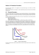
2.4 Overcurrent (50-n, 51-n)
2.4.1.1
Instantaneous Overcurrent (50-n)
This is applied to protect the motor connections against phase-phase short circuits. The setting should be either
above the motor start current, or inhibited during motor starting e.g. via a binary input. Note that charging of motor
PF correction capacitors where fitted will increase motor starting current.
As the motor is the final point of load in the network there is no requirement to coordinate the overcurrent
protection with any downstream devices, the protection can be set to operate instantaneously.
2.4.2 Time Delayed Overcurrent (51-n)
Generally instantaneous overcurrent is applied to protect the motor terminal connections. Time delayed
overcurrent may be used when the relay is utilised in non motor applications.
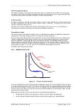
2.5 Earth-fault Protection (50G/50N)
Earth fault current levels will be limited by the earth fault impedance the motor and associated plant. It may be
difficult to make an effective short circuit to earth due to the nature of the installation and/or system earthing
method and the earth fault current may therefore be limited to very low levels.
Where very sensitive current settings are required then it is preferable to use a core balance CT rather than wire
into the residual connection of the line CTs. The turns ratio of a core balance CT can be much smaller than that of
phase conductors as it is not related to the rated current of the protected circuit. Since only one core is used, the
CT magnetising current losses are also reduced by a factor of three.
There are limits to how sensitive an earth fault relay may be set since the setting must be above any line charging
current levels that can be detected by the relay. On occurrence of an out of zone earth fault the elevation of sound
phase voltage to earth in a non-effectively earthed system can result in a zero sequence current of up 3 times
phase charging current flowing through the relay location. The step change from balanced 3-phase charging
currents to this level of zero sequence current includes transients. It is recommended to
•
Apply directional earth fault protection, or
•
Allow for a transient factor of 2 to 3 when determining the limit of charging current. Based on the above
considerations the minimum setting of a relay in a resistance earthed power system is 6 to 9 times the
charging current per phase.
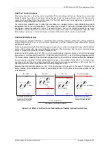
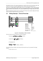
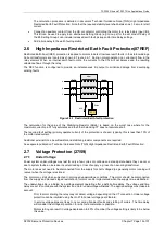
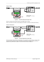
Circuit 1
Circuit 2
Core
Balance
CT
Incomer
M
M
Holmgreen
connection
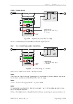
Circuit 4
Snubbing
resistor
M
Circuit 3
M
Directional
Earth
Fault
Figure 2.5-1 Earth Fault Protection Applications
During motor starting the higher currents may cause some CT saturation to occur because of the long dc offsets.
For the residual (Holmgreen) earth current measuring connection, unequal CT saturation may cause false
residual current to flow. It is recommended to use one of the following methods:
•
Add a ‘snubbing’ resistor ensure that the earth fault element operate voltage is higher than that which
can be produced by current flowing through the saturated CT phase winding. This has the disadvantage
of increasing the CT burden for a real motor earth fault. Note that with this method the resistor is only
required during motor starting and will reduce the earth fault protection sensitivity.
Содержание 7SR105 Rho
Страница 1: ...Answers for energy 7SR105 Rho User Manual Motor Protection Relay Reyrolle Protection Devices ...
Страница 2: ...Siemens Protection Devices 2 ...
Страница 95: ...7SR105 Rho Technical Manual Chapter 4 Page 2 of 70 2018 Siemens Protection Devices ...
Страница 99: ...7SR105 Rho Technical Manual Chapter 4 Page 6 of 70 2018 Siemens Protection Devices ...
Страница 127: ...7SR105 Rho Technical Manual Chapter 4 Page 34 of 70 2018 Siemens Protection Devices ...
Страница 153: ...7SR105 Rho Technical Manual Chapter 4 Page 60 of 70 2018 Siemens Protection Devices ...
Страница 155: ...7SR105 Rho Technical Manual Chapter 4 Page 62 of 70 2018 Siemens Protection Devices ...
Страница 157: ...7SR105 Rho Technical Manual Chapter 4 Page 64 of 70 2018 Siemens Protection Devices ...