7SR105 Rho and 7SR17 Rho Applications Guide
©2018 Siemens Protection Devices
Chapter 7 Page 3 of 31
List of Figures
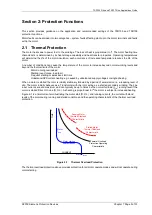
Figure 2-1
Thermal Overload Protection ........................................................................................................ 5
Figure 2-2
Summary of Protection Settings Calculation Procedure ................................................................. 6
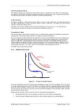
Figure 2.1-3
Thermal Heating (Cold) Characteristics ......................................................................................... 8
Figure 2.1-4
Effect of Hot/Cold Curve Ratio Setting on Thermal Overload Operate Time .................................... 9
Figure 2-5
Thermal Overload Protection ...................................................................................................... 10
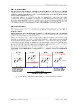
Figure 2.1-6
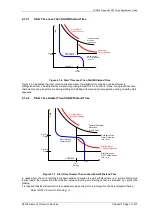
Start Time Less Than Stall Withstand Time ................................................................................. 11
Figure 2.1-7
Start Time Greater Than Locked Rotor Withstand Time ............................................................... 11
Figure 2.2-1
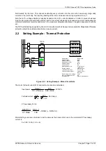
Setting Example – Motor Circuit Data .......................................................................................... 13
Figure 2.2-2
Summary of Thermal Settings ..................................................................................................... 16
Figure 2.5-1
Earth Fault Protection Applications.............................................................................................. 18
Figure 2.6-1
Restricted Earth-fault protection .................................................................................................. 19
Figure 4-1
Logic Diagram: Trip Circuit Supervision Feature (74TCS) ............................................................ 24
Figure 4-2
Logic Diagram: Close Circuit Supervision Feature (74CCS) ......................................................... 24
Figure 4-3
Trip Circuit Supervision Scheme 1 (H5) ....................................................................................... 25
Figure 4-4
Trip Circuit Supervision Scheme 2 (H6) ....................................................................................... 25
Figure 4-5
Trip Circuit Supervision Scheme 3 (H7) ....................................................................................... 26
Figure 4-6
Close Circuit Supervision Scheme .............................................................................................. 26
Содержание 7SR105 Rho
Страница 1: ...Answers for energy 7SR105 Rho User Manual Motor Protection Relay Reyrolle Protection Devices ...
Страница 2: ...Siemens Protection Devices 2 ...
Страница 95: ...7SR105 Rho Technical Manual Chapter 4 Page 2 of 70 2018 Siemens Protection Devices ...
Страница 99: ...7SR105 Rho Technical Manual Chapter 4 Page 6 of 70 2018 Siemens Protection Devices ...
Страница 127: ...7SR105 Rho Technical Manual Chapter 4 Page 34 of 70 2018 Siemens Protection Devices ...
Страница 153: ...7SR105 Rho Technical Manual Chapter 4 Page 60 of 70 2018 Siemens Protection Devices ...
Страница 155: ...7SR105 Rho Technical Manual Chapter 4 Page 62 of 70 2018 Siemens Protection Devices ...
Страница 157: ...7SR105 Rho Technical Manual Chapter 4 Page 64 of 70 2018 Siemens Protection Devices ...

