7SG12 DAD N Description of Operation
2.5 Fascia LEDS
In the E8 case there are 16 user programmable red LED flag indicators. By opening the front panel it is
possible to insert a label strip into a slip in pocket, which provides legend information about the meaning of
each LED. The legend may be specified when ordering the relay or alternatively the user can create a
customized legend. The user can customise which LED is used for which purpose as well as being able to
program each LED as being latching or self –resetting.
2.6 Self Monitoring
The relay incorporates a number of self-monitoring features. Each of these features can initiate a
controlled reset recovery sequence, which can be used to generate an alarm output. In addition, the
Protection Healthy LED will give visual indication.
A watchdog timer continuously monitors the microprocessor. The voltage rails are also continuously
supervised and the microprocessor is reset if any of the rails falls outside of their working ranges. Any
failure is detected in sufficient time so that the microprocessor can be shut down in a safe and controlled
manner.
2.6.1 Protection Healthy/Defective
The normally closed contacts of relay 1 are used to signal protection defective, whilst the normally open
contacts are used to signal protection healthy. When the DC supply is not applied to the relay or a problem
is detected with the operation of the relay then this relay is de-energised and the normally closed contacts
make to provide an external alarm. When the relay has DC supply and it has successfully passed its self-
checking procedure then the Protection Healthy contacts are made and the Protection Defective contacts
are opened.
3 Protection Functions
3.1 Overall Differential (87/50-1, 87/50-2)
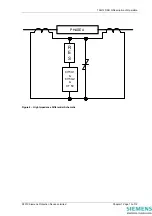
The Overall Differential protection uses the high impedance circulating current principle, a single line
diagram of such a scheme is shown in Figure 4 – High Impedance Differential Schematic. The protection
consists of a DTL over-current element 87/50 per phase which is used for tripping.
Transient stability under through fault conditions is a problem with many forms of differential protection,
due to variations in CT magnetising characteristics. When saturation is approached the current transformer
output waveforms become increasingly distorted with a high percentage of 3
rd
and other harmonics. The
algorithms employed in the Overall Differential protection ensure complete harmonic rejection thus
improving overall protection stability.
In addition the settings for high impedance differential protection are calculated assuming that one CT is
completely saturated. Using this worst case condition the voltage (determined by the value of the
stabilising resistor) and current settings for the 87/50 elements can be precisely calculated with known
stability margins. Intermediate conditions where the CT is only partially saturated increases the stability
margin. This approach enables schemes to be engineered with relatively low knee-point voltages.
There are two stages of protection, 87/50-1 and 87/50-2 both of which are identical.
3.2 CT Supervision (CT 50)
To check for CT continuity an overcurrent element (50) is available. During healthy CT conditions the
current in the differential circuit is zero. If one CT becomes open circuit the current contribution from that
CT will flow through the relay. If the setting is below this level of current the relay CT alarm will operate.
3.3 Trip Circuit Supervision
Status inputs on the relay can be used to supervise the trip circuit while the associated circuit breaker (CB)
is either open or closed. Each trip circuit monitored can independently be programmed to operate output
contacts, LEDs and events.
To use the function set ‘Trip Cct
n
Pickup Delay’ to the required value in the Trip Circuit Supervision Menu
and then map the ‘Trip Cct Fail
n
’ settings in the Status Input Menu, Output Relay Menu and LED Menu as
required.
©2010 Siemens Protection Devices Limited
Chapter 1 Page 5 of 14
Содержание 7SG12 DAD-N
Страница 2: ......

