7SG12 DAD N Applications Guide
3.1 Stabilising Resistor
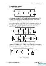
Consider a simple 4 CT protection:
Relay
Figure 2 – Simple 4 CT Protection
It is a proven design principle that the worst case for current unbalance due to CT saturation occurs when
one of the paralleled CTs becomes completely saturated while all the other CTs continue to function
linearly. This situation would never occur in reality, but by making the protection tolerant to it we can be
confident that it will remain stable for all through fault conditions.
When a CT becomes total saturated, its secondary winding can be considered as a resistance rather than
a current source. The value of this resistance is equal to the CT secondary resistance, R
ct
, and will be
considerably larger than the resistance of the Relay analogue inputs. This means that most of the
unbalanced currents from the other CTs will flow through the Relay and these may be of sufficient
magnitude to operate the protection.
Relay
0A
1A
2A
2A
1A
Relay
2A
2A
1A
1A
R
ct
>> R
relay
Figure 3 – Current Distribution with one CT totally saturated
The solution is to load the Relay circuit by adding a series resistor such that most of the unbalance current
due to the CT becoming saturated will instead flow through the saturated CT secondary. Since this resistor
will make the protection stable for all through faults, it is termed the Stabilising Resistor, Rstab. Similarly, it
is this additional resistance which makes the Relay a “High Impedance” path.
Relay
2A
2A
1A
R
stab
>> R
ct
Figure 4 – Stabilising Resistor
©2010 Siemens Protection Devices Limited
Chapter 5 Page 4 of 16
Содержание 7SG12 DAD-N
Страница 2: ......

