background image

KIT INSTALLATION INSTRUCTION

Siemens
Energy & Automation


Kit Part Numbers:  16300-468 Standard Flow 

15900-407 


16330-469 High Flow

 Rev. 


16300-470 Low Gain Flow

 January 

2009 


Series 760 Valve Positioner 

Output Capacity Kit 

 
Install an Output Capacity Kit to match Positioner flow output to an Actuator. This Instruction 
describes installation of the kits listed above. Refer to the Series 760 Valve Positioner Installation 
and Service Instruction, SD760, as needed during installation of a kit. 

KIT CONTENTS 

Each Kit contains the items listed below. Note that the Spool Valve (Spool Block and Spool) in each of the three kits 
is different. 

If several kits are being installed, keep the parts in each kit separate.


Item Quantity 

Spool Valve (Spool and Spool Block) 

Spool Clip


Valve Block Gasket, Viton®/Nomex® 

Valve Block Gasket, Neoprene/Nylon 

8-32 Spool Block Mounting Screws 

Kit Installation Instruction 

KIT INSTALLATION 

The area in which the Kit is installed must be clean. Hands and tools must also be clean. Keep all Kit parts in the 
supplied bag until they are to be installed to prevent contamination by dust, dirt, fumes, and other environmental 
contaminants. Contaminants can cause the spool to stick or operate unevenly.  
 

IMPORTANT 


Move the positioner to a clean location before installing the kit. If this is not possible, contaminants 
must be prevented from entering exposed air passageways during kit installation. 


WARNING


Electrical shock hazard 

Explosion hazard 


Can cause death or injury 


Remove power from all wires and terminals before working on 
equipment. 


In potentially hazardous atmosphere, remove power from equipment 
before connecting or disconnecting power, signal, or other circuit. 


Observe all pertinent regulations regarding installation in hazardous 
area.


Содержание 760 Series

Страница 1: ...t Viton Nomex 1 Valve Block Gasket Neoprene Nylon 1 8 32 Spool Block Mounting Screws 2 Kit Installation Instruction 1 KIT INSTALLATION The area in which the Kit is installed must be clean Hands and tools must also be clean Keep all Kit parts in the supplied bag until they are to be installed to prevent contamination by dust dirt fumes and other environmental contaminants Contaminants can cause the...

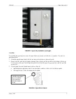
Страница 2: ...y Remove the I P transducer Refer to SD760 as needed See Figure 1 FIGURE 1 I P Transducer Cam and CAMLOC not shown 7 At the spool block see Figures 2 and 3 carefully note how the spool clip is installed At the top of the block the clip is inserted in the countersink in the end of the spool At the bottom of the block the clip end is in the bronze bushing in the underside of the beam assembly 8 Remo...

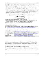
Страница 3: ...s tubular container Place a finger over the spool hole in the bottom of the spool block to prevent the spool from falling through the block Insert the spool long journal first into the top of the spool block 3 Select a gasket from the Output Capacity Kit see Figure 4 High temperature application or an ozone atmospheric condition Select the Viton Nomex gasket Other applications Select the neoprene ...

Страница 4: ...ntative visit the Siemens Process Instrumentation product support page at http www2 sea siemens com Products Process Instrumentation Support Customer Support htm For technical support refer to the following table and click the appropriate link Technical Support Online Support Request http www siemens com automation support request Telephone 1 800 333 7421 Hours of Operation 8 a m to 4 45 p m easte...

Отзывы: